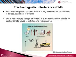
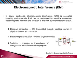
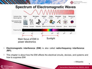
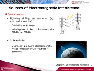
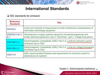
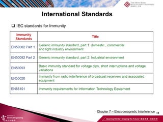
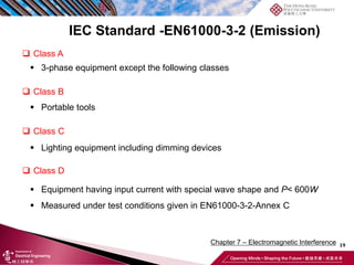
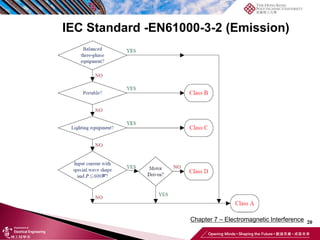
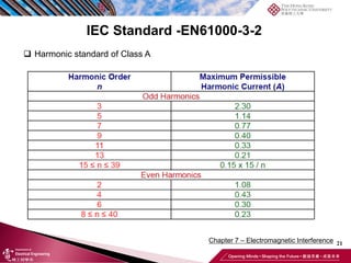
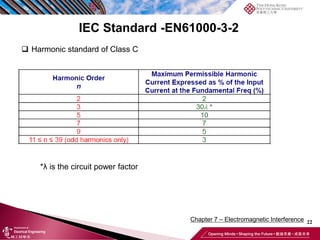
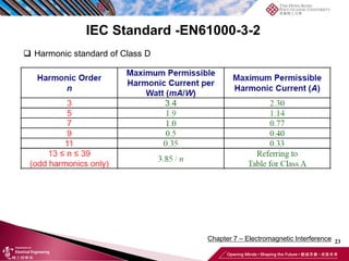
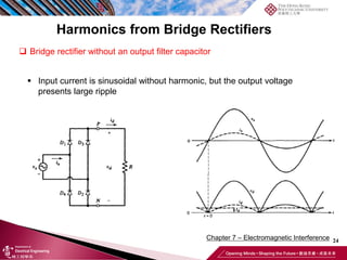
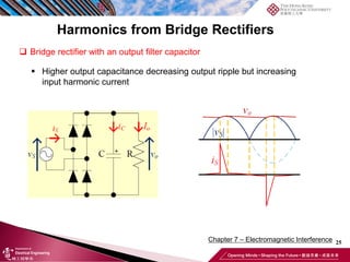
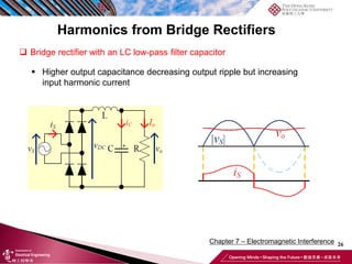
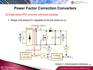
SlideShare a Scribd company logo
Chapter 7 – Electromagnetic Interference of
Power Electronics
1
Advanced Power Electronics (EE4007A/B/D)
19/11/2019
Outline
2
Chapter 7 – Electromagnetic Interference
• Electromagnetic interference (EMI) generation and transmission
• International standards about EMI
• EMI suppression methods
• EMI related power quality issues
3
Chapter 6 – Electromagnetic Interference
Electromagnetic Interference (EMI)
• EMI - Electromagnetic disturbance leads to degradation of the performance
of devices, equipment or systems
• EMI is not a varying voltage or current. It is the harmful effect caused by
electromagnetic waves or fast changing voltage/current
4
Chapter 7 – Electromagnetic Interference
Electromagnetic Interference (EMI)
• In power electronics, electromagnetic interference (EMI) is generated
internally and externally. EMI can be transmitted by electrical conduction,
electromagnetic induction and radiation to and from a power electronic circuit.
❖ Electrical conduction – EMI transmitted through electrical current in
physical channel such as cable.
❖ Electromagnetic induction – without physical contact
❖ Radiation - emission or transmission of
energy in the form of waves through space
5
Spectrum of Electromagnetic Waves
• Electromagnetic interference (EMI) is also called radio-frequency interference
(RFI).
Sunlight
Main focus of EMI in
power electronics
-- Wikipedia
• This chapter is about how the EMI affects the electrical circuits, devices, and systems and
how to suppress EMI
6
Chapter 7 – Electromagnetic Interference
Sources of Electromagnetic Interference
❑ Natural sources
▪ Lightning striking on conductor (eg.
overhead power line)
• Producing large surge
• Inducing electric field in frequency with
50MHz to 100MHz
▪ Solar radiation
• Cosmic ray producing electromagnetic
waves in frequency with 100MHz to
1000MHz
7
Chapter 7 – Electromagnetic Interference
Sources of Electromagnetic Interference
❑ Man-made Sources
▪ Electrostatic discharges (ESD)
• Sudden flow of electricity between two electrically charged objects
caused by contact
▪ Electromagnetic Pulse (EMP)
• From nuclear explosions or any systems or weapons with this
function (eg. EMP Bombs)
▪ Variations in mains supply voltage
• From malfunction of power systems
• From tripping of circuit breakers
• From sudden change of output of power generators, critical loads
and reactive power (VAR)
8
Chapter 7 – Electromagnetic Interference
Sources of Electromagnetic Interference
❑ Man-made Sources
▪ Electrical and electronic sub-systems producing noise from
• Systems and parts in automotive such as ignition systems,
alternators and electric machines
• Power distribution systems including power lines, static VAR
compensators (SVC) and generator stations
• Industrial equipment such as welding machines, induction heaters,
circuit breakers, variable speed drives and oscillators
• Radio transmitters including all mobile communication systems
• Emitted waves generated by switching transient of high frequency
systems such as SMPS and inverters
• Harmonics of input current of appliances from SMPS, motor drives
and any appliances without power factor correction
9
Chapter 7 – Electromagnetic Interference
❑ Media of EMI transmission from power electronics
EMI from power electronics
❑ Switching of transistors
▪ Rapid changed of current (di/dt)
• Generating high transient voltage with parasitic inductor
▪ Rapid change of voltage (dv/dt)
• Generating high leakage current through stray capacitance
(electrostatic coupling)
▪ EMI generated internally in a power electronic circuit may be spread to
the line and the load by electrical conduction, and to the surrounding by
electromagnetic induction, electrostatic coupling and radiation.
10
Chapter 7– Electromagnetic Interference
EMI from power electronics
❑ Harmonics of input current
▪ EMI transmitted by conduction
▪ Degrading power quality
▪ Generating EMI
▪ Examples of power electronics
• Bridge rectifiers, Static VAR compensators (SVC), controlled
rectifier, switched mode converters without good input filtering
11
Chapter 7 – Electromagnetic Interference
EMI to power electronics
❑ From power network by conduction
▪ Poor power quality
• Harmonics
▪ Sudden change of power generators and
appliance
• Voltage surge and sags (dv/dt)
▪ Noise in power line
❑ Noise through electromagnetic induction and radiation
▪ Electrical machine, transmitters, mobile phone and remote
signal transmission equipment
12
Chapter 7 – Electromagnetic Interference
Definition of Terms of EMI and Harmonics
❑ Electromagnetic Interference (EMI)
▪ Electromagnetic disturbance degrading performance of devices,
equipment or system
▪ Low EMI is preferred
❑ Electromagnetic Compatibility (EMC)
▪ Ability of an equipment or system to function satisfactorily in its
electromagnetic environment without introducing intolerable
electromagnetic disturbances to anything, in that environment
▪ High EMC is preferred
13
Chapter 7 – Electromagnetic Interference
Definition of Terms of EMI and Harmonics
❑ Emission
▪ Phenomenon which which electromagnetic energy emits from a source
▪ Divided into conductive emission and radiated emission
❑ Immunity (what is the difference to EMC?)
▪ Ability of a device, an equipment or a system to perform without
degradation in presence of an electromagnetic disturbance. In other
words, the ability to withstand the EMI
14
Chapter 7 – Electromagnetic Interference
Definition of Terms of EMI and Harmonics
❑ Susceptibility (the inverse of immunity)
▪ Inability of a device, an equipment or a system to perform without
degradation in the presence of an electromagnetic disturbance
❑ Total Harmonic Distortion (THD)
▪ RMS addition of all harmonics, except the fundamental, as compared to
fundamental component
▪ THD can be higher than 100%
▪ Good power quality if THD < 15%
Harmonics is one of the sources causing EMI
15
Chapter 7 – Electromagnetic Interference
International Standards
❑ The British Standards Institute (BSI) -UK
❑ The Federal Communications Commission (FCC) -USA
❑ Verband Deutscher Elektrotechniker (VDE) -Germany
❑ The International Electrotechnical Commission (IEC) -EU
❑ The International Special Committee on Radio Interference
(CISPR) -IEC
▪ Subcommittee of IEC
▪ Firstly proposing EMC standards
❑ CE Mark -EU
❑ Why are Standards needed?
16
Chapter 7 – Electromagnetic Interference
International Standards
❑ IEC standards for emission
17
Chapter 7 – Electromagnetic Interference
International Standards
❑ IEC standards for emission
18
Chapter 7 – Electromagnetic Interference
International Standards
❑ IEC standards for Immunity
19
Chapter 7 – Electromagnetic Interference
IEC Standard -EN61000-3-2 (Emission)
❑ Class A
▪ 3-phase equipment except the following classes
❑ Class B
▪ Portable tools
❑ Class C
▪ Lighting equipment including dimming devices
❑ Class D
▪ Equipment having input current with special wave shape and P< 600W
▪ Measured under test conditions given in EN61000-3-2-Annex C
20
Chapter 7 – Electromagnetic Interference
IEC Standard -EN61000-3-2 (Emission)
21
Chapter 7 – Electromagnetic Interference
IEC Standard -EN61000-3-2
❑ Harmonic standard of Class A
22
Chapter 7 – Electromagnetic Interference
IEC Standard -EN61000-3-2
❑ Harmonic standard of Class C
*λ is the circuit power factor
23
Chapter 7 – Electromagnetic Interference
IEC Standard -EN61000-3-2
❑ Harmonic standard of Class D
24
Chapter 7 – Electromagnetic Interference
Harmonics from Bridge Rectifiers
❑ Bridge rectifier without an output filter capacitor
▪ Input current is sinusoidal without harmonic, but the output voltage
presents large ripple
25
Chapter 7 – Electromagnetic Interference
▪ Higher output capacitance decreasing output ripple but increasing
input harmonic current
Harmonics from Bridge Rectifiers
❑ Bridge rectifier with an output filter capacitor
26
Chapter 7 – Electromagnetic Interference
▪ Higher output capacitance decreasing output ripple but increasing
input harmonic current
Harmonics from Bridge Rectifiers
❑ Bridge rectifier with an LC low-pass filter capacitor
27
Chapter 7 – Electromagnetic Interference
Power Factor Correction Converters
❑ Power factor correction (PFC) converters can be used for voltage
rectification with regulated DC output voltage to solve the above input
harmonic current and power factor problem.
❑ AC/DC converter with very high PF and regulated output voltage
❑ Closed-loop controlled for I/P current and O/P voltage
▪ Shape of input current regulated to be half sinusoidal
▪ Phase of input current regulated to be in phase with I/P voltage
❑ Peak current mode control or average current mode control
❑ Size of output filtering capacitor NOT able to be reduced by increasing
switching frequency
28
Chapter 7 – Electromagnetic Interference
Power Factor Correction Converters
❑ Single phase PFC converter with boost topology
▪ Shape and phase of iL regulated to be the same as vDC
29
Chapter 7 – Electromagnetic Interference
Power Factor Correction Converters
❑ 3-phase full bridge PFCC
30
Chapter 7 – Electromagnetic Interference
Active Harmonic Compensation
❑ Harmonic active filters eliminating a range or whole range of harmonics
❑ Compensating displacement VAR
❑ Fast response
❑ For shunt type, shunt connected to the line
▪ Switched mode converter (Inverters)
▪ Current mode closed-loop control
▪ Similar to STATCOM
▪ Series type active filter similar to SSSC
31
Chapter 7 – Electromagnetic Interference
Active Harmonic Compensation
❑ Constructed with a bidirectional 3-phase full-bridge inverter
▪ 3-ph Inverter →6 boost converters sharing 3 input inductors
❑ Large capacitor as energy storage device and power source
Diagram of a shunt active filter
32
❑ When the power line current is higher than the reference current, the large capacitor provides
power to the inverter to generate the amount of exceeding current to the load through the
power line instantaneously.
❑ When the power line current is lower than the reference current, the bidirectional inverter acts
as a boost converter (similar topology of 3-phase power factor correction converter with boost
topology). The active power filter inputs the amount of current under the reference current
instantaneously to the converter to charge the capacitor.
Active Harmonic Compensation
Control objective: grid current are sinusoidal currents
Operation principle: i_load (ila, ila, ila) = i_grid (ia, ib, ic) + i_filter (i1, i2, i3)
Grid current
33
Chapter 7 – Electromagnetic Interference
Types of Electromagnetic Interference
❑ Differential mode noise
❑ Common mode noise
▪ EMI conducting through conductors to and from input lines
▪ EMI conducting through stray capacitors by electrostatic coupling
between power lines and ground
❑ Both types of EMI in AC current or voltage manner
❑ Suppressing EMI necessary for meeting standard
▪ EMI suppression filters commonly used
▪ Different types of filters for different types of EMI
34
Chapter 7 – Electromagnetic Interference
Types of Electromagnetic Interference
Noise from converter
Noise to converter
35
Chapter 7 – Electromagnetic Interference
Differential Mode Noise Suppression
❑ Differential mode chokes
▪ Using magnetic components (a pair of inductors)
❑ Class X capacitors
▪ Shunt connected capacitor at the input of the converter
36
Chapter 7 – Electromagnetic Interference
❑ Constructed with a pair of inductors
▪ Connected to input of converter
▪ Providing high reactance of noise (high frequencies)
▪ AC current of noise reduced
Differential Mode Noise Suppression
37
Chapter 7 – Electromagnetic Interference
❑ Varistor, Also called voltage dependent resistor
❑ Connected in the input of the whole converter circuit
❑ With nonlinear and variable resistance characteristic with different voltage
▪ Very high resistance during normal operation
▪ Resistance decreasing while increasing voltage
▪ Resistance decreasing drastically while voltage beyond rated voltage
Differential Mode Noise Suppression
38
Chapter 7 – Electromagnetic Interference
❑ Resistance of varistor is very low during surge occurring
❑ Current returning to the power lines
▪ Circuit protected from differential mode voltage surge
▪ Especially surge during switching on the converters
❑ Selecting varistors with different varistor voltage, maximum clamping
voltage and maximum energy (Joule, J)
Differential Mode Noise Suppression
39
Chapter 7 – Electromagnetic Interference
Other Methods for Reducing EMI
❑ Good design of transformers and inductors
▪ Using toroid cores to reducing leakage magnetic flux
❑ Electrical isolation of power converters isolating differential mode
noise by the transformer
❑ Applying snubber circuits for decreasing dv/dt but this decreasing
efficiency of the converters
❑ Applying soft-switching techniques to reduce switching loss, di/dt and
or dv/dt of transistors
40
Chapter 7 – Electromagnetic Interference
Other Methods for Reducing EMI
❑ Good PCB tracks and components arrangement
▪ Decreasing inner area of PCB tracks of current loop ()
▪ Decreasing length of tracks
❑ Using double layer PCB with ground on the top layer
▪ The ground on the top layer absorbing external and internal EMI
• The routine of current forms a current loop. Decreasing inner
area of the current loop or decreasing the length the tracks can
reduce parasitic inductance and EMI

More Related Content

What's hot

Electronic Measurement - Q Factor and Q Meter
Electronic Measurement - Q Factor and Q MeterElectronic Measurement - Q Factor and Q Meter
Electronic Measurement - Q Factor and Q Meter
Burdwan University
 
Power System Protection
Power System ProtectionPower System Protection
Power System Protection
Sumeet Ratnawat
 
Chapter 3
Chapter 3Chapter 3
Chapter 3
Yimam Alemu
 
Instrument transformer CT & PT
Instrument transformer CT & PTInstrument transformer CT & PT
Instrument transformer CT & PT
Chandan Singh
 
Chapter1 breakdown in gases
Chapter1 breakdown in gasesChapter1 breakdown in gases
Chapter1 breakdown in gases
mukund mukund.m
 
protection for power system
protection for power systemprotection for power system
protection for power system
MONTHER Taha
 
Voltage Source Inverter VSI - Pulse Width Modulation (PWM)
Voltage Source Inverter VSI - Pulse Width Modulation (PWM)Voltage Source Inverter VSI - Pulse Width Modulation (PWM)
Voltage Source Inverter VSI - Pulse Width Modulation (PWM)
Citharthan Durairaj
 
IGBT
IGBTIGBT
Measurement of high_voltage_and_high_currentunit_iv_full_version
Measurement of high_voltage_and_high_currentunit_iv_full_versionMeasurement of high_voltage_and_high_currentunit_iv_full_version
Measurement of high_voltage_and_high_currentunit_iv_full_version
Aman Ansari
 
Pulse width modulated inverter
Pulse width modulated inverterPulse width modulated inverter
Pulse width modulated inverter
VSRAGHU
 
Power Electronics - Power Semi – Conductor Devices
Power Electronics - Power Semi – Conductor DevicesPower Electronics - Power Semi – Conductor Devices
Power Electronics - Power Semi – Conductor Devices
Burdwan University
 
Firing angle control
Firing angle controlFiring angle control
Firing angle control
jawaharramaya
 
Speed control of IM using Space Vector Modulation
Speed control of IM using Space Vector ModulationSpeed control of IM using Space Vector Modulation
Speed control of IM using Space Vector Modulation
Asif Jamadar
 
COMPENSATION OF REACTIVE POWER
COMPENSATION OF REACTIVE POWERCOMPENSATION OF REACTIVE POWER
COMPENSATION OF REACTIVE POWER
ST Chowhury
 
Report On diode clamp three level inverter
Report On diode clamp three level inverterReport On diode clamp three level inverter
Report On diode clamp three level inverter
Vinay Singh
 
EDS Unit 4 (Protection and Coordination).pptx
EDS Unit 4 (Protection and Coordination).pptxEDS Unit 4 (Protection and Coordination).pptx
EDS Unit 4 (Protection and Coordination).pptx
Dr. Rohit Babu
 
Flying Capacitor Multi Level Inverter
Flying Capacitor Multi Level InverterFlying Capacitor Multi Level Inverter
Flying Capacitor Multi Level Inverter
Sajid Sheikh
 
Unit 2 resonance circuit
Unit 2 resonance circuitUnit 2 resonance circuit
Unit 2 resonance circuit
ACE ENGINEERING COLLEGE
 
Circuit breaker, Types of circuit breaker & different CB related questions
Circuit breaker, Types of circuit breaker & different CB related questionsCircuit breaker, Types of circuit breaker & different CB related questions
Circuit breaker, Types of circuit breaker & different CB related questions
Urooj Abid
 

What's hot (20)

Electronic Measurement - Q Factor and Q Meter
Electronic Measurement - Q Factor and Q MeterElectronic Measurement - Q Factor and Q Meter
Electronic Measurement - Q Factor and Q Meter
 
Power System Protection
Power System ProtectionPower System Protection
Power System Protection
 
Chapter 3
Chapter 3Chapter 3
Chapter 3
 
Instrument transformer CT & PT
Instrument transformer CT & PTInstrument transformer CT & PT
Instrument transformer CT & PT
 
Chapter1 breakdown in gases
Chapter1 breakdown in gasesChapter1 breakdown in gases
Chapter1 breakdown in gases
 
protection for power system
protection for power systemprotection for power system
protection for power system
 
Voltage Source Inverter VSI - Pulse Width Modulation (PWM)
Voltage Source Inverter VSI - Pulse Width Modulation (PWM)Voltage Source Inverter VSI - Pulse Width Modulation (PWM)
Voltage Source Inverter VSI - Pulse Width Modulation (PWM)
 
IGBT
IGBTIGBT
IGBT
 
Measurement of high_voltage_and_high_currentunit_iv_full_version
Measurement of high_voltage_and_high_currentunit_iv_full_versionMeasurement of high_voltage_and_high_currentunit_iv_full_version
Measurement of high_voltage_and_high_currentunit_iv_full_version
 
Pulse width modulated inverter
Pulse width modulated inverterPulse width modulated inverter
Pulse width modulated inverter
 
132 kv
132 kv132 kv
132 kv
 
Power Electronics - Power Semi – Conductor Devices
Power Electronics - Power Semi – Conductor DevicesPower Electronics - Power Semi – Conductor Devices
Power Electronics - Power Semi – Conductor Devices
 
Firing angle control
Firing angle controlFiring angle control
Firing angle control
 
Speed control of IM using Space Vector Modulation
Speed control of IM using Space Vector ModulationSpeed control of IM using Space Vector Modulation
Speed control of IM using Space Vector Modulation
 
COMPENSATION OF REACTIVE POWER
COMPENSATION OF REACTIVE POWERCOMPENSATION OF REACTIVE POWER
COMPENSATION OF REACTIVE POWER
 
Report On diode clamp three level inverter
Report On diode clamp three level inverterReport On diode clamp three level inverter
Report On diode clamp three level inverter
 
EDS Unit 4 (Protection and Coordination).pptx
EDS Unit 4 (Protection and Coordination).pptxEDS Unit 4 (Protection and Coordination).pptx
EDS Unit 4 (Protection and Coordination).pptx
 
Flying Capacitor Multi Level Inverter
Flying Capacitor Multi Level InverterFlying Capacitor Multi Level Inverter
Flying Capacitor Multi Level Inverter
 
Unit 2 resonance circuit
Unit 2 resonance circuitUnit 2 resonance circuit
Unit 2 resonance circuit
 
Circuit breaker, Types of circuit breaker & different CB related questions
Circuit breaker, Types of circuit breaker & different CB related questionsCircuit breaker, Types of circuit breaker & different CB related questions
Circuit breaker, Types of circuit breaker & different CB related questions
 

Similar to Chapter 7 - EMI.pdf

Powerqualityppt kuldeep
Powerqualityppt kuldeepPowerqualityppt kuldeep
Powerqualityppt kuldeepKuldeep Singh
 
Power quality
Power  qualityPower  quality
Power quality
Sowmya Reddy
 
powerqualityppt-130820010049-phpapp02.pdf
powerqualityppt-130820010049-phpapp02.pdfpowerqualityppt-130820010049-phpapp02.pdf
powerqualityppt-130820010049-phpapp02.pdf
giahuy646563
 
Electromagnetic Interference and Electromagnetic Compatibility (EMI/EMC
Electromagnetic Interference and Electromagnetic Compatibility (EMI/EMCElectromagnetic Interference and Electromagnetic Compatibility (EMI/EMC
Electromagnetic Interference and Electromagnetic Compatibility (EMI/EMC
Aishwary Singh
 
International Journal of Computational Engineering Research (IJCER)
International Journal of Computational Engineering Research (IJCER)International Journal of Computational Engineering Research (IJCER)
International Journal of Computational Engineering Research (IJCER)
ijceronline
 
Power Quality
Power QualityPower Quality
Power Quality
Elshemy Mohamed
 
POWER QUALITY IMPROVEMENT
POWER QUALITY IMPROVEMENTPOWER QUALITY IMPROVEMENT
POWER QUALITY IMPROVEMENT
Uday Wankar
 
UG POWER QUALITY (EE2028) ppt
UG POWER QUALITY (EE2028) pptUG POWER QUALITY (EE2028) ppt
UG POWER QUALITY (EE2028) ppt
Harris Raj
 
Distribu pQ.pptx
Distribu pQ.pptxDistribu pQ.pptx
Distribu pQ.pptx
bhuvana71
 
Power Quality Improvement using AC To AC PWM converter for distribution line
Power Quality Improvement using AC To AC PWM converter for distribution linePower Quality Improvement using AC To AC PWM converter for distribution line
Power Quality Improvement using AC To AC PWM converter for distribution line
International Journal of Engineering Inventions www.ijeijournal.com
 
Power Electronics Introduction
Power Electronics IntroductionPower Electronics Introduction
Power Electronics Introduction
PoornimaDhandapani2
 
Protection & switchgear
Protection & switchgear   Protection & switchgear
Protection & switchgear
johny renoald
 
Electromagnetic pulse generator(emp bomb)
Electromagnetic pulse generator(emp bomb)   Electromagnetic pulse generator(emp bomb)
Electromagnetic pulse generator(emp bomb)
raja sukumar
 
Power Electronics introduction
Power Electronics introductionPower Electronics introduction
Power Electronics introduction
Poornima D
 
1660034363151685.pptx
1660034363151685.pptx1660034363151685.pptx
1660034363151685.pptx
Pradip khatri
 
Power quality 1
Power quality 1Power quality 1
Power quality 1
Md Irshad Ahmad
 

Similar to Chapter 7 - EMI.pdf (20)

Powerqualityppt kuldeep
Powerqualityppt kuldeepPowerqualityppt kuldeep
Powerqualityppt kuldeep
 
Power quality
Power  qualityPower  quality
Power quality
 
power_ quality
power_ qualitypower_ quality
power_ quality
 
powerqualityppt-130820010049-phpapp02.pdf
powerqualityppt-130820010049-phpapp02.pdfpowerqualityppt-130820010049-phpapp02.pdf
powerqualityppt-130820010049-phpapp02.pdf
 
Power quality ppt
Power quality pptPower quality ppt
Power quality ppt
 
Electromagnetic Interference and Electromagnetic Compatibility (EMI/EMC
Electromagnetic Interference and Electromagnetic Compatibility (EMI/EMCElectromagnetic Interference and Electromagnetic Compatibility (EMI/EMC
Electromagnetic Interference and Electromagnetic Compatibility (EMI/EMC
 
International Journal of Computational Engineering Research (IJCER)
International Journal of Computational Engineering Research (IJCER)International Journal of Computational Engineering Research (IJCER)
International Journal of Computational Engineering Research (IJCER)
 
Power Quality
Power QualityPower Quality
Power Quality
 
POWER QUALITY IMPROVEMENT
POWER QUALITY IMPROVEMENTPOWER QUALITY IMPROVEMENT
POWER QUALITY IMPROVEMENT
 
UG POWER QUALITY (EE2028) ppt
UG POWER QUALITY (EE2028) pptUG POWER QUALITY (EE2028) ppt
UG POWER QUALITY (EE2028) ppt
 
Distribu pQ.pptx
Distribu pQ.pptxDistribu pQ.pptx
Distribu pQ.pptx
 
Power Quality Improvement using AC To AC PWM converter for distribution line
Power Quality Improvement using AC To AC PWM converter for distribution linePower Quality Improvement using AC To AC PWM converter for distribution line
Power Quality Improvement using AC To AC PWM converter for distribution line
 
Power Electronics Introduction
Power Electronics IntroductionPower Electronics Introduction
Power Electronics Introduction
 
Power quality
Power qualityPower quality
Power quality
 
Protection & switchgear
Protection & switchgear   Protection & switchgear
Protection & switchgear
 
Electromagnetic pulse generator(emp bomb)
Electromagnetic pulse generator(emp bomb)   Electromagnetic pulse generator(emp bomb)
Electromagnetic pulse generator(emp bomb)
 
Power Electronics introduction
Power Electronics introductionPower Electronics introduction
Power Electronics introduction
 
1660034363151685.pptx
1660034363151685.pptx1660034363151685.pptx
1660034363151685.pptx
 
Power quality 1
Power quality 1Power quality 1
Power quality 1
 
Protection and Switchgear
Protection and SwitchgearProtection and Switchgear
Protection and Switchgear
 

More from benson215

Chapter 5 - DC-AC Conversion.pdf
Chapter 5 - DC-AC Conversion.pdfChapter 5 - DC-AC Conversion.pdf
Chapter 5 - DC-AC Conversion.pdf
benson215
 
Chapter 0 - Introduction.pdf
Chapter 0 - Introduction.pdfChapter 0 - Introduction.pdf
Chapter 0 - Introduction.pdf
benson215
 
Chapter 1 - PWM DC-DC Converter.pdf
Chapter 1 - PWM DC-DC Converter.pdfChapter 1 - PWM DC-DC Converter.pdf
Chapter 1 - PWM DC-DC Converter.pdf
benson215
 
Chapter 2 - Isolated DC-DC Converter.pdf
Chapter 2 - Isolated DC-DC Converter.pdfChapter 2 - Isolated DC-DC Converter.pdf
Chapter 2 - Isolated DC-DC Converter.pdf
benson215
 
Chapter 3 - Resonant-mode DC-DC Converter.pdf
Chapter 3 - Resonant-mode DC-DC Converter.pdfChapter 3 - Resonant-mode DC-DC Converter.pdf
Chapter 3 - Resonant-mode DC-DC Converter.pdf
benson215
 
Chapter 6 - Modelling and Control of Converters.pdf
Chapter 6 - Modelling and Control of Converters.pdfChapter 6 - Modelling and Control of Converters.pdf
Chapter 6 - Modelling and Control of Converters.pdf
benson215
 
Chapter 4 - AC-DC Conversion.pdf
Chapter 4 - AC-DC Conversion.pdfChapter 4 - AC-DC Conversion.pdf
Chapter 4 - AC-DC Conversion.pdf
benson215
 
3. ac drive (misc.)
3. ac drive (misc.)3. ac drive (misc.)
3. ac drive (misc.)
benson215
 
2. ac drive (common inverter drive)
2. ac drive (common inverter drive)2. ac drive (common inverter drive)
2. ac drive (common inverter drive)
benson215
 
1. revision on 3 phase conventional inverter
1. revision on 3 phase conventional inverter1. revision on 3 phase conventional inverter
1. revision on 3 phase conventional inverter
benson215
 
2. dc drive
2. dc drive2. dc drive
2. dc drive
benson215
 
1. revision on 3 phase controlled rectifier
1. revision on 3 phase controlled rectifier1. revision on 3 phase controlled rectifier
1. revision on 3 phase controlled rectifier
benson215
 
2. motor drive dynamic
2. motor drive dynamic2. motor drive dynamic
2. motor drive dynamic
benson215
 
5. two phase servo motor
5. two phase servo motor5. two phase servo motor
5. two phase servo motor
benson215
 
4. linear motor basics
4. linear motor basics4. linear motor basics
4. linear motor basics
benson215
 
2. brushless dc motors
2. brushless dc motors2. brushless dc motors
2. brushless dc motors
benson215
 
1. servo basic
1. servo basic1. servo basic
1. servo basic
benson215
 
3. relutance and hysteresis motor
3. relutance and hysteresis motor3. relutance and hysteresis motor
3. relutance and hysteresis motor
benson215
 
Eee3420 lecture08 rev2011
Eee3420 lecture08 rev2011Eee3420 lecture08 rev2011
Eee3420 lecture08 rev2011
benson215
 
Eee3420 lecture07 rev2011
Eee3420 lecture07 rev2011Eee3420 lecture07 rev2011
Eee3420 lecture07 rev2011
benson215
 

More from benson215 (20)

Chapter 5 - DC-AC Conversion.pdf
Chapter 5 - DC-AC Conversion.pdfChapter 5 - DC-AC Conversion.pdf
Chapter 5 - DC-AC Conversion.pdf
 
Chapter 0 - Introduction.pdf
Chapter 0 - Introduction.pdfChapter 0 - Introduction.pdf
Chapter 0 - Introduction.pdf
 
Chapter 1 - PWM DC-DC Converter.pdf
Chapter 1 - PWM DC-DC Converter.pdfChapter 1 - PWM DC-DC Converter.pdf
Chapter 1 - PWM DC-DC Converter.pdf
 
Chapter 2 - Isolated DC-DC Converter.pdf
Chapter 2 - Isolated DC-DC Converter.pdfChapter 2 - Isolated DC-DC Converter.pdf
Chapter 2 - Isolated DC-DC Converter.pdf
 
Chapter 3 - Resonant-mode DC-DC Converter.pdf
Chapter 3 - Resonant-mode DC-DC Converter.pdfChapter 3 - Resonant-mode DC-DC Converter.pdf
Chapter 3 - Resonant-mode DC-DC Converter.pdf
 
Chapter 6 - Modelling and Control of Converters.pdf
Chapter 6 - Modelling and Control of Converters.pdfChapter 6 - Modelling and Control of Converters.pdf
Chapter 6 - Modelling and Control of Converters.pdf
 
Chapter 4 - AC-DC Conversion.pdf
Chapter 4 - AC-DC Conversion.pdfChapter 4 - AC-DC Conversion.pdf
Chapter 4 - AC-DC Conversion.pdf
 
3. ac drive (misc.)
3. ac drive (misc.)3. ac drive (misc.)
3. ac drive (misc.)
 
2. ac drive (common inverter drive)
2. ac drive (common inverter drive)2. ac drive (common inverter drive)
2. ac drive (common inverter drive)
 
1. revision on 3 phase conventional inverter
1. revision on 3 phase conventional inverter1. revision on 3 phase conventional inverter
1. revision on 3 phase conventional inverter
 
2. dc drive
2. dc drive2. dc drive
2. dc drive
 
1. revision on 3 phase controlled rectifier
1. revision on 3 phase controlled rectifier1. revision on 3 phase controlled rectifier
1. revision on 3 phase controlled rectifier
 
2. motor drive dynamic
2. motor drive dynamic2. motor drive dynamic
2. motor drive dynamic
 
5. two phase servo motor
5. two phase servo motor5. two phase servo motor
5. two phase servo motor
 
4. linear motor basics
4. linear motor basics4. linear motor basics
4. linear motor basics
 
2. brushless dc motors
2. brushless dc motors2. brushless dc motors
2. brushless dc motors
 
1. servo basic
1. servo basic1. servo basic
1. servo basic
 
3. relutance and hysteresis motor
3. relutance and hysteresis motor3. relutance and hysteresis motor
3. relutance and hysteresis motor
 
Eee3420 lecture08 rev2011
Eee3420 lecture08 rev2011Eee3420 lecture08 rev2011
Eee3420 lecture08 rev2011
 
Eee3420 lecture07 rev2011
Eee3420 lecture07 rev2011Eee3420 lecture07 rev2011
Eee3420 lecture07 rev2011
 

Recently uploaded

weather web application report.pdf
weather web application report.pdfweather web application report.pdf
weather web application report.pdf
Pratik Pawar
 
space technology lecture notes on satellite
space technology lecture notes on satellitespace technology lecture notes on satellite
space technology lecture notes on satellite
ongomchris
 
Sachpazis:Terzaghi Bearing Capacity Estimation in simple terms with Calculati...
Sachpazis:Terzaghi Bearing Capacity Estimation in simple terms with Calculati...Sachpazis:Terzaghi Bearing Capacity Estimation in simple terms with Calculati...
Sachpazis:Terzaghi Bearing Capacity Estimation in simple terms with Calculati...
Dr.Costas Sachpazis
 
DESIGN A COTTON SEED SEPARATION MACHINE.docx
DESIGN A COTTON SEED SEPARATION MACHINE.docxDESIGN A COTTON SEED SEPARATION MACHINE.docx
DESIGN A COTTON SEED SEPARATION MACHINE.docx
FluxPrime1
 
CME397 Surface Engineering- Professional Elective
CME397 Surface Engineering- Professional ElectiveCME397 Surface Engineering- Professional Elective
CME397 Surface Engineering- Professional Elective
karthi keyan
 
Design and Analysis of Algorithms-DP,Backtracking,Graphs,B&B
Design and Analysis of Algorithms-DP,Backtracking,Graphs,B&BDesign and Analysis of Algorithms-DP,Backtracking,Graphs,B&B
Design and Analysis of Algorithms-DP,Backtracking,Graphs,B&B
Sreedhar Chowdam
 
WATER CRISIS and its solutions-pptx 1234
WATER CRISIS and its solutions-pptx 1234WATER CRISIS and its solutions-pptx 1234
WATER CRISIS and its solutions-pptx 1234
AafreenAbuthahir2
 
Hybrid optimization of pumped hydro system and solar- Engr. Abdul-Azeez.pdf
Hybrid optimization of pumped hydro system and solar- Engr. Abdul-Azeez.pdfHybrid optimization of pumped hydro system and solar- Engr. Abdul-Azeez.pdf
Hybrid optimization of pumped hydro system and solar- Engr. Abdul-Azeez.pdf
fxintegritypublishin
 
ASME IX(9) 2007 Full Version .pdf
ASME IX(9)  2007 Full Version       .pdfASME IX(9)  2007 Full Version       .pdf
ASME IX(9) 2007 Full Version .pdf
AhmedHussein950959
 
road safety engineering r s e unit 3.pdf
road safety engineering  r s e unit 3.pdfroad safety engineering  r s e unit 3.pdf
road safety engineering r s e unit 3.pdf
VENKATESHvenky89705
 
Top 10 Oil and Gas Projects in Saudi Arabia 2024.pdf
Top 10 Oil and Gas Projects in Saudi Arabia 2024.pdfTop 10 Oil and Gas Projects in Saudi Arabia 2024.pdf
Top 10 Oil and Gas Projects in Saudi Arabia 2024.pdf
Teleport Manpower Consultant
 
Gen AI Study Jams _ For the GDSC Leads in India.pdf
Gen AI Study Jams _ For the GDSC Leads in India.pdfGen AI Study Jams _ For the GDSC Leads in India.pdf
Gen AI Study Jams _ For the GDSC Leads in India.pdf
gdsczhcet
 
在线办理(ANU毕业证书)澳洲国立大学毕业证录取通知书一模一样
在线办理(ANU毕业证书)澳洲国立大学毕业证录取通知书一模一样在线办理(ANU毕业证书)澳洲国立大学毕业证录取通知书一模一样
在线办理(ANU毕业证书)澳洲国立大学毕业证录取通知书一模一样
obonagu
 
Cosmetic shop management system project report.pdf
Cosmetic shop management system project report.pdfCosmetic shop management system project report.pdf
Cosmetic shop management system project report.pdf
Kamal Acharya
 
Fundamentals of Electric Drives and its applications.pptx
Fundamentals of Electric Drives and its applications.pptxFundamentals of Electric Drives and its applications.pptx
Fundamentals of Electric Drives and its applications.pptx
manasideore6
 
The role of big data in decision making.
The role of big data in decision making.The role of big data in decision making.
The role of big data in decision making.
ankuprajapati0525
 
Architectural Portfolio Sean Lockwood
Architectural Portfolio Sean LockwoodArchitectural Portfolio Sean Lockwood
Architectural Portfolio Sean Lockwood
seandesed
 
RAT: Retrieval Augmented Thoughts Elicit Context-Aware Reasoning in Long-Hori...
RAT: Retrieval Augmented Thoughts Elicit Context-Aware Reasoning in Long-Hori...RAT: Retrieval Augmented Thoughts Elicit Context-Aware Reasoning in Long-Hori...
RAT: Retrieval Augmented Thoughts Elicit Context-Aware Reasoning in Long-Hori...
thanhdowork
 
Immunizing Image Classifiers Against Localized Adversary Attacks
Immunizing Image Classifiers Against Localized Adversary AttacksImmunizing Image Classifiers Against Localized Adversary Attacks
Immunizing Image Classifiers Against Localized Adversary Attacks
gerogepatton
 
CFD Simulation of By-pass Flow in a HRSG module by R&R Consult.pptx
CFD Simulation of By-pass Flow in a HRSG module by R&R Consult.pptxCFD Simulation of By-pass Flow in a HRSG module by R&R Consult.pptx
CFD Simulation of By-pass Flow in a HRSG module by R&R Consult.pptx
R&R Consult
 

Recently uploaded (20)

weather web application report.pdf
weather web application report.pdfweather web application report.pdf
weather web application report.pdf
 
space technology lecture notes on satellite
space technology lecture notes on satellitespace technology lecture notes on satellite
space technology lecture notes on satellite
 
Sachpazis:Terzaghi Bearing Capacity Estimation in simple terms with Calculati...
Sachpazis:Terzaghi Bearing Capacity Estimation in simple terms with Calculati...Sachpazis:Terzaghi Bearing Capacity Estimation in simple terms with Calculati...
Sachpazis:Terzaghi Bearing Capacity Estimation in simple terms with Calculati...
 
DESIGN A COTTON SEED SEPARATION MACHINE.docx
DESIGN A COTTON SEED SEPARATION MACHINE.docxDESIGN A COTTON SEED SEPARATION MACHINE.docx
DESIGN A COTTON SEED SEPARATION MACHINE.docx
 
CME397 Surface Engineering- Professional Elective
CME397 Surface Engineering- Professional ElectiveCME397 Surface Engineering- Professional Elective
CME397 Surface Engineering- Professional Elective
 
Design and Analysis of Algorithms-DP,Backtracking,Graphs,B&B
Design and Analysis of Algorithms-DP,Backtracking,Graphs,B&BDesign and Analysis of Algorithms-DP,Backtracking,Graphs,B&B
Design and Analysis of Algorithms-DP,Backtracking,Graphs,B&B
 
WATER CRISIS and its solutions-pptx 1234
WATER CRISIS and its solutions-pptx 1234WATER CRISIS and its solutions-pptx 1234
WATER CRISIS and its solutions-pptx 1234
 
Hybrid optimization of pumped hydro system and solar- Engr. Abdul-Azeez.pdf
Hybrid optimization of pumped hydro system and solar- Engr. Abdul-Azeez.pdfHybrid optimization of pumped hydro system and solar- Engr. Abdul-Azeez.pdf
Hybrid optimization of pumped hydro system and solar- Engr. Abdul-Azeez.pdf
 
ASME IX(9) 2007 Full Version .pdf
ASME IX(9)  2007 Full Version       .pdfASME IX(9)  2007 Full Version       .pdf
ASME IX(9) 2007 Full Version .pdf
 
road safety engineering r s e unit 3.pdf
road safety engineering  r s e unit 3.pdfroad safety engineering  r s e unit 3.pdf
road safety engineering r s e unit 3.pdf
 
Top 10 Oil and Gas Projects in Saudi Arabia 2024.pdf
Top 10 Oil and Gas Projects in Saudi Arabia 2024.pdfTop 10 Oil and Gas Projects in Saudi Arabia 2024.pdf
Top 10 Oil and Gas Projects in Saudi Arabia 2024.pdf
 
Gen AI Study Jams _ For the GDSC Leads in India.pdf
Gen AI Study Jams _ For the GDSC Leads in India.pdfGen AI Study Jams _ For the GDSC Leads in India.pdf
Gen AI Study Jams _ For the GDSC Leads in India.pdf
 
在线办理(ANU毕业证书)澳洲国立大学毕业证录取通知书一模一样
在线办理(ANU毕业证书)澳洲国立大学毕业证录取通知书一模一样在线办理(ANU毕业证书)澳洲国立大学毕业证录取通知书一模一样
在线办理(ANU毕业证书)澳洲国立大学毕业证录取通知书一模一样
 
Cosmetic shop management system project report.pdf
Cosmetic shop management system project report.pdfCosmetic shop management system project report.pdf
Cosmetic shop management system project report.pdf
 
Fundamentals of Electric Drives and its applications.pptx
Fundamentals of Electric Drives and its applications.pptxFundamentals of Electric Drives and its applications.pptx
Fundamentals of Electric Drives and its applications.pptx
 
The role of big data in decision making.
The role of big data in decision making.The role of big data in decision making.
The role of big data in decision making.
 
Architectural Portfolio Sean Lockwood
Architectural Portfolio Sean LockwoodArchitectural Portfolio Sean Lockwood
Architectural Portfolio Sean Lockwood
 
RAT: Retrieval Augmented Thoughts Elicit Context-Aware Reasoning in Long-Hori...
RAT: Retrieval Augmented Thoughts Elicit Context-Aware Reasoning in Long-Hori...RAT: Retrieval Augmented Thoughts Elicit Context-Aware Reasoning in Long-Hori...
RAT: Retrieval Augmented Thoughts Elicit Context-Aware Reasoning in Long-Hori...
 
Immunizing Image Classifiers Against Localized Adversary Attacks
Immunizing Image Classifiers Against Localized Adversary AttacksImmunizing Image Classifiers Against Localized Adversary Attacks
Immunizing Image Classifiers Against Localized Adversary Attacks
 
CFD Simulation of By-pass Flow in a HRSG module by R&R Consult.pptx
CFD Simulation of By-pass Flow in a HRSG module by R&R Consult.pptxCFD Simulation of By-pass Flow in a HRSG module by R&R Consult.pptx
CFD Simulation of By-pass Flow in a HRSG module by R&R Consult.pptx
 

Chapter 7 - EMI.pdf

  • 1. Chapter 7 – Electromagnetic Interference of Power Electronics 1 Advanced Power Electronics (EE4007A/B/D) 19/11/2019
  • 2. Outline 2 Chapter 7 – Electromagnetic Interference • Electromagnetic interference (EMI) generation and transmission • International standards about EMI • EMI suppression methods • EMI related power quality issues
  • 3. 3 Chapter 6 – Electromagnetic Interference Electromagnetic Interference (EMI) • EMI - Electromagnetic disturbance leads to degradation of the performance of devices, equipment or systems • EMI is not a varying voltage or current. It is the harmful effect caused by electromagnetic waves or fast changing voltage/current
  • 4. 4 Chapter 7 – Electromagnetic Interference Electromagnetic Interference (EMI) • In power electronics, electromagnetic interference (EMI) is generated internally and externally. EMI can be transmitted by electrical conduction, electromagnetic induction and radiation to and from a power electronic circuit. ❖ Electrical conduction – EMI transmitted through electrical current in physical channel such as cable. ❖ Electromagnetic induction – without physical contact ❖ Radiation - emission or transmission of energy in the form of waves through space
  • 5. 5 Spectrum of Electromagnetic Waves • Electromagnetic interference (EMI) is also called radio-frequency interference (RFI). Sunlight Main focus of EMI in power electronics -- Wikipedia • This chapter is about how the EMI affects the electrical circuits, devices, and systems and how to suppress EMI
  • 6. 6 Chapter 7 – Electromagnetic Interference Sources of Electromagnetic Interference ❑ Natural sources ▪ Lightning striking on conductor (eg. overhead power line) • Producing large surge • Inducing electric field in frequency with 50MHz to 100MHz ▪ Solar radiation • Cosmic ray producing electromagnetic waves in frequency with 100MHz to 1000MHz
  • 7. 7 Chapter 7 – Electromagnetic Interference Sources of Electromagnetic Interference ❑ Man-made Sources ▪ Electrostatic discharges (ESD) • Sudden flow of electricity between two electrically charged objects caused by contact ▪ Electromagnetic Pulse (EMP) • From nuclear explosions or any systems or weapons with this function (eg. EMP Bombs) ▪ Variations in mains supply voltage • From malfunction of power systems • From tripping of circuit breakers • From sudden change of output of power generators, critical loads and reactive power (VAR)
  • 8. 8 Chapter 7 – Electromagnetic Interference Sources of Electromagnetic Interference ❑ Man-made Sources ▪ Electrical and electronic sub-systems producing noise from • Systems and parts in automotive such as ignition systems, alternators and electric machines • Power distribution systems including power lines, static VAR compensators (SVC) and generator stations • Industrial equipment such as welding machines, induction heaters, circuit breakers, variable speed drives and oscillators • Radio transmitters including all mobile communication systems • Emitted waves generated by switching transient of high frequency systems such as SMPS and inverters • Harmonics of input current of appliances from SMPS, motor drives and any appliances without power factor correction
  • 9. 9 Chapter 7 – Electromagnetic Interference ❑ Media of EMI transmission from power electronics EMI from power electronics ❑ Switching of transistors ▪ Rapid changed of current (di/dt) • Generating high transient voltage with parasitic inductor ▪ Rapid change of voltage (dv/dt) • Generating high leakage current through stray capacitance (electrostatic coupling) ▪ EMI generated internally in a power electronic circuit may be spread to the line and the load by electrical conduction, and to the surrounding by electromagnetic induction, electrostatic coupling and radiation.
  • 10. 10 Chapter 7– Electromagnetic Interference EMI from power electronics ❑ Harmonics of input current ▪ EMI transmitted by conduction ▪ Degrading power quality ▪ Generating EMI ▪ Examples of power electronics • Bridge rectifiers, Static VAR compensators (SVC), controlled rectifier, switched mode converters without good input filtering
  • 11. 11 Chapter 7 – Electromagnetic Interference EMI to power electronics ❑ From power network by conduction ▪ Poor power quality • Harmonics ▪ Sudden change of power generators and appliance • Voltage surge and sags (dv/dt) ▪ Noise in power line ❑ Noise through electromagnetic induction and radiation ▪ Electrical machine, transmitters, mobile phone and remote signal transmission equipment
  • 12. 12 Chapter 7 – Electromagnetic Interference Definition of Terms of EMI and Harmonics ❑ Electromagnetic Interference (EMI) ▪ Electromagnetic disturbance degrading performance of devices, equipment or system ▪ Low EMI is preferred ❑ Electromagnetic Compatibility (EMC) ▪ Ability of an equipment or system to function satisfactorily in its electromagnetic environment without introducing intolerable electromagnetic disturbances to anything, in that environment ▪ High EMC is preferred
  • 13. 13 Chapter 7 – Electromagnetic Interference Definition of Terms of EMI and Harmonics ❑ Emission ▪ Phenomenon which which electromagnetic energy emits from a source ▪ Divided into conductive emission and radiated emission ❑ Immunity (what is the difference to EMC?) ▪ Ability of a device, an equipment or a system to perform without degradation in presence of an electromagnetic disturbance. In other words, the ability to withstand the EMI
  • 14. 14 Chapter 7 – Electromagnetic Interference Definition of Terms of EMI and Harmonics ❑ Susceptibility (the inverse of immunity) ▪ Inability of a device, an equipment or a system to perform without degradation in the presence of an electromagnetic disturbance ❑ Total Harmonic Distortion (THD) ▪ RMS addition of all harmonics, except the fundamental, as compared to fundamental component ▪ THD can be higher than 100% ▪ Good power quality if THD < 15% Harmonics is one of the sources causing EMI
  • 15. 15 Chapter 7 – Electromagnetic Interference International Standards ❑ The British Standards Institute (BSI) -UK ❑ The Federal Communications Commission (FCC) -USA ❑ Verband Deutscher Elektrotechniker (VDE) -Germany ❑ The International Electrotechnical Commission (IEC) -EU ❑ The International Special Committee on Radio Interference (CISPR) -IEC ▪ Subcommittee of IEC ▪ Firstly proposing EMC standards ❑ CE Mark -EU ❑ Why are Standards needed?
  • 16. 16 Chapter 7 – Electromagnetic Interference International Standards ❑ IEC standards for emission
  • 17. 17 Chapter 7 – Electromagnetic Interference International Standards ❑ IEC standards for emission
  • 18. 18 Chapter 7 – Electromagnetic Interference International Standards ❑ IEC standards for Immunity
  • 19. 19 Chapter 7 – Electromagnetic Interference IEC Standard -EN61000-3-2 (Emission) ❑ Class A ▪ 3-phase equipment except the following classes ❑ Class B ▪ Portable tools ❑ Class C ▪ Lighting equipment including dimming devices ❑ Class D ▪ Equipment having input current with special wave shape and P< 600W ▪ Measured under test conditions given in EN61000-3-2-Annex C
  • 20. 20 Chapter 7 – Electromagnetic Interference IEC Standard -EN61000-3-2 (Emission)
  • 21. 21 Chapter 7 – Electromagnetic Interference IEC Standard -EN61000-3-2 ❑ Harmonic standard of Class A
  • 22. 22 Chapter 7 – Electromagnetic Interference IEC Standard -EN61000-3-2 ❑ Harmonic standard of Class C *λ is the circuit power factor
  • 23. 23 Chapter 7 – Electromagnetic Interference IEC Standard -EN61000-3-2 ❑ Harmonic standard of Class D
  • 24. 24 Chapter 7 – Electromagnetic Interference Harmonics from Bridge Rectifiers ❑ Bridge rectifier without an output filter capacitor ▪ Input current is sinusoidal without harmonic, but the output voltage presents large ripple
  • 25. 25 Chapter 7 – Electromagnetic Interference ▪ Higher output capacitance decreasing output ripple but increasing input harmonic current Harmonics from Bridge Rectifiers ❑ Bridge rectifier with an output filter capacitor
  • 26. 26 Chapter 7 – Electromagnetic Interference ▪ Higher output capacitance decreasing output ripple but increasing input harmonic current Harmonics from Bridge Rectifiers ❑ Bridge rectifier with an LC low-pass filter capacitor
  • 27. 27 Chapter 7 – Electromagnetic Interference Power Factor Correction Converters ❑ Power factor correction (PFC) converters can be used for voltage rectification with regulated DC output voltage to solve the above input harmonic current and power factor problem. ❑ AC/DC converter with very high PF and regulated output voltage ❑ Closed-loop controlled for I/P current and O/P voltage ▪ Shape of input current regulated to be half sinusoidal ▪ Phase of input current regulated to be in phase with I/P voltage ❑ Peak current mode control or average current mode control ❑ Size of output filtering capacitor NOT able to be reduced by increasing switching frequency
  • 28. 28 Chapter 7 – Electromagnetic Interference Power Factor Correction Converters ❑ Single phase PFC converter with boost topology ▪ Shape and phase of iL regulated to be the same as vDC
  • 29. 29 Chapter 7 – Electromagnetic Interference Power Factor Correction Converters ❑ 3-phase full bridge PFCC
  • 30. 30 Chapter 7 – Electromagnetic Interference Active Harmonic Compensation ❑ Harmonic active filters eliminating a range or whole range of harmonics ❑ Compensating displacement VAR ❑ Fast response ❑ For shunt type, shunt connected to the line ▪ Switched mode converter (Inverters) ▪ Current mode closed-loop control ▪ Similar to STATCOM ▪ Series type active filter similar to SSSC
  • 31. 31 Chapter 7 – Electromagnetic Interference Active Harmonic Compensation ❑ Constructed with a bidirectional 3-phase full-bridge inverter ▪ 3-ph Inverter →6 boost converters sharing 3 input inductors ❑ Large capacitor as energy storage device and power source Diagram of a shunt active filter
  • 32. 32 ❑ When the power line current is higher than the reference current, the large capacitor provides power to the inverter to generate the amount of exceeding current to the load through the power line instantaneously. ❑ When the power line current is lower than the reference current, the bidirectional inverter acts as a boost converter (similar topology of 3-phase power factor correction converter with boost topology). The active power filter inputs the amount of current under the reference current instantaneously to the converter to charge the capacitor. Active Harmonic Compensation Control objective: grid current are sinusoidal currents Operation principle: i_load (ila, ila, ila) = i_grid (ia, ib, ic) + i_filter (i1, i2, i3) Grid current
  • 33. 33 Chapter 7 – Electromagnetic Interference Types of Electromagnetic Interference ❑ Differential mode noise ❑ Common mode noise ▪ EMI conducting through conductors to and from input lines ▪ EMI conducting through stray capacitors by electrostatic coupling between power lines and ground ❑ Both types of EMI in AC current or voltage manner ❑ Suppressing EMI necessary for meeting standard ▪ EMI suppression filters commonly used ▪ Different types of filters for different types of EMI
  • 34. 34 Chapter 7 – Electromagnetic Interference Types of Electromagnetic Interference Noise from converter Noise to converter
  • 35. 35 Chapter 7 – Electromagnetic Interference Differential Mode Noise Suppression ❑ Differential mode chokes ▪ Using magnetic components (a pair of inductors) ❑ Class X capacitors ▪ Shunt connected capacitor at the input of the converter
  • 36. 36 Chapter 7 – Electromagnetic Interference ❑ Constructed with a pair of inductors ▪ Connected to input of converter ▪ Providing high reactance of noise (high frequencies) ▪ AC current of noise reduced Differential Mode Noise Suppression
  • 37. 37 Chapter 7 – Electromagnetic Interference ❑ Varistor, Also called voltage dependent resistor ❑ Connected in the input of the whole converter circuit ❑ With nonlinear and variable resistance characteristic with different voltage ▪ Very high resistance during normal operation ▪ Resistance decreasing while increasing voltage ▪ Resistance decreasing drastically while voltage beyond rated voltage Differential Mode Noise Suppression
  • 38. 38 Chapter 7 – Electromagnetic Interference ❑ Resistance of varistor is very low during surge occurring ❑ Current returning to the power lines ▪ Circuit protected from differential mode voltage surge ▪ Especially surge during switching on the converters ❑ Selecting varistors with different varistor voltage, maximum clamping voltage and maximum energy (Joule, J) Differential Mode Noise Suppression
  • 39. 39 Chapter 7 – Electromagnetic Interference Other Methods for Reducing EMI ❑ Good design of transformers and inductors ▪ Using toroid cores to reducing leakage magnetic flux ❑ Electrical isolation of power converters isolating differential mode noise by the transformer ❑ Applying snubber circuits for decreasing dv/dt but this decreasing efficiency of the converters ❑ Applying soft-switching techniques to reduce switching loss, di/dt and or dv/dt of transistors
  • 40. 40 Chapter 7 – Electromagnetic Interference Other Methods for Reducing EMI ❑ Good PCB tracks and components arrangement ▪ Decreasing inner area of PCB tracks of current loop () ▪ Decreasing length of tracks ❑ Using double layer PCB with ground on the top layer ▪ The ground on the top layer absorbing external and internal EMI • The routine of current forms a current loop. Decreasing inner area of the current loop or decreasing the length the tracks can reduce parasitic inductance and EMI