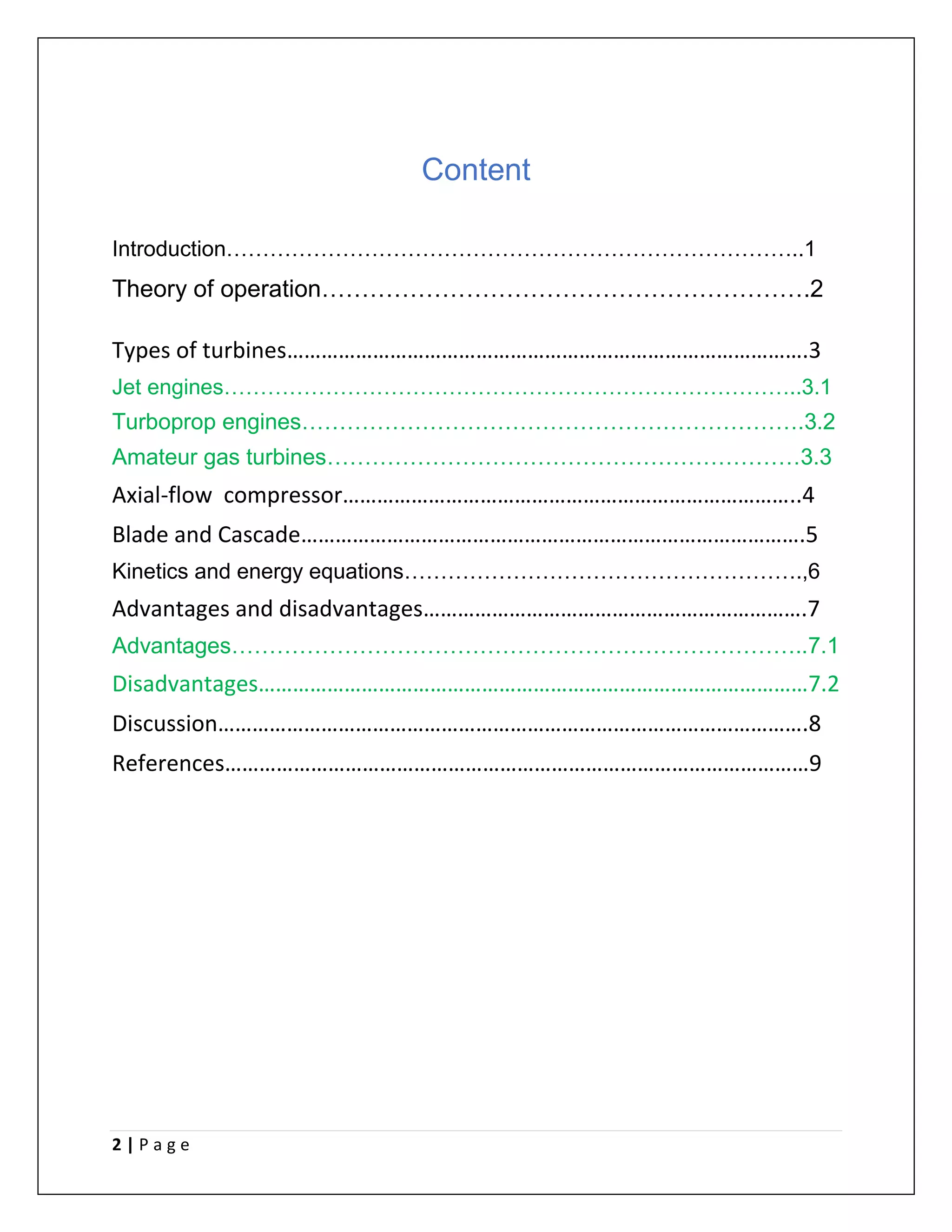
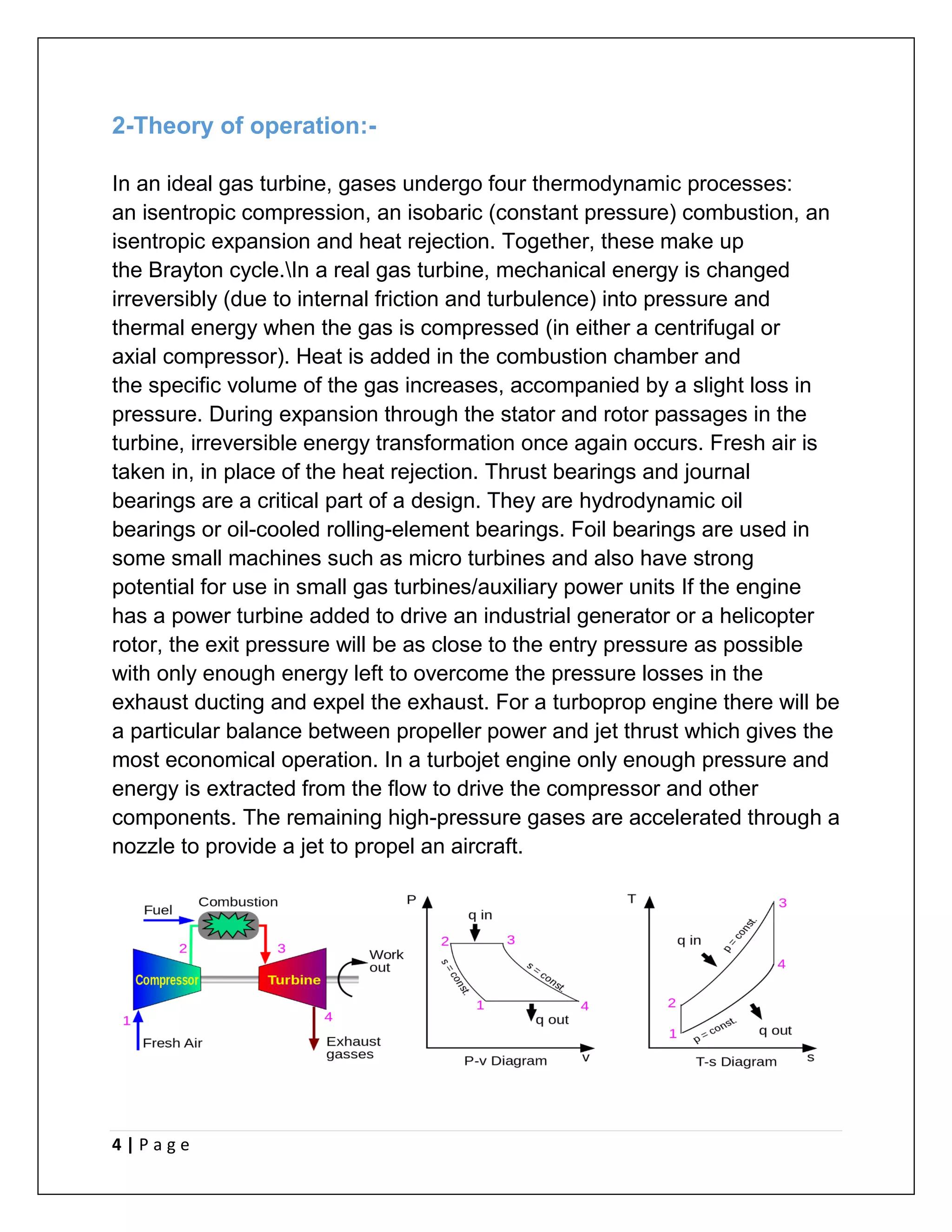
This document provides an overview of gas turbine engines. It discusses the basic components and operation of gas turbines, including the compressor, combustor, and turbine. It also describes different types of gas turbine engines like jet engines, turboprop engines, and amateur gas turbines. Key aspects like the axial-flow compressor, blade design, kinetics and energy equations are explained. Finally, the advantages of high power-to-weight ratio and small size are contrasted with the disadvantages of high fuel consumption and emissions.
1. 1 | P a g e
University Of Baghdad
College Of Engineering
Mechanical Department
Turbine machines
(Gas turbine)
:االسم
-
حمزة مرزة حاتم عدي
A : الشعبة
-
: المرحلة
-
الثالثة
2. 2 | P a g e
Content
Introduction……………………………………………………………………..1
Theory of operation…………………………………………………….2
Types of turbines……………………………………………………………………………….3
Jet engines……………………………………………………………………..3.1
Turboprop engines………………………………………………………….3.2
Amateur gas turbines………………………………………………………3.3
Axial-flow compressor……………………………………………………………………..4
Blade and Cascade…………………………………………………………………………….5
Kinetics and energy equations……………………………………………….,6
Advantages and disadvantages………………………………………………………….7
Advantages…………………………………………………………………..7.1
Disadvantages……………………………………………………………………………………7.2
Discussion………………………………………………………………………………………….8
References…………………………………………………………………………………………9
3. 3 | P a g e
1-introduction:-
A gas turbine, also called a combustion turbine, is a type
of continuous and internal combustion engine. The main elements common
to all gas turbine engines are: an upstream rotating gas compressor
a combustor a downstream turbine on the same shaft as the compressor.A
fourth component is often used to increase efficiency
(on turboprops and turbofans), to convert power into mechanical or electric
form (on turboshafts and electric generators), or to achieve greater thrust-
to-weight ratio (on afterburning engines). The basic operation of the gas
turbine is a Brayton cycle with air as the working fluid : atmospheric air
flows through the compressor that brings it to higher pressure ; energy is
then added by spraying fuel into the air and igniting it so that the
combustion generates a high-temperature flow ; this high-temperature
pressurized gas enters a turbine, producing a shaft work output in the
process, used to drive the compressor ; the unused energy comes out in
the exhaust gases that can be repurposed for external work, such as
directly producing thrust in a turbojet engine, or rotating a second,
independent turbine (known as a power turbine) that can be connected to a
fan, propeller, or electrical generator.. Gas turbines are used to power
aircraft, trains, ships, electrical generators, pumps, gas compressors,
and tanks.
4. 4 | P a g e
2-Theory of operation:-
In an ideal gas turbine, gases undergo four thermodynamic processes:
an isentropic compression, an isobaric (constant pressure) combustion, an
isentropic expansion and heat rejection. Together, these make up
the Brayton cycle.In a real gas turbine, mechanical energy is changed
irreversibly (due to internal friction and turbulence) into pressure and
thermal energy when the gas is compressed (in either a centrifugal or
axial compressor). Heat is added in the combustion chamber and
the specific volume of the gas increases, accompanied by a slight loss in
pressure. During expansion through the stator and rotor passages in the
turbine, irreversible energy transformation once again occurs. Fresh air is
taken in, in place of the heat rejection. Thrust bearings and journal
bearings are a critical part of a design. They are hydrodynamic oil
bearings or oil-cooled rolling-element bearings. Foil bearings are used in
some small machines such as micro turbines and also have strong
potential for use in small gas turbines/auxiliary power units If the engine
has a power turbine added to drive an industrial generator or a helicopter
rotor, the exit pressure will be as close to the entry pressure as possible
with only enough energy left to overcome the pressure losses in the
exhaust ducting and expel the exhaust. For a turboprop engine there will be
a particular balance between propeller power and jet thrust which gives the
most economical operation. In a turbojet engine only enough pressure and
energy is extracted from the flow to drive the compressor and other
components. The remaining high-pressure gases are accelerated through a
nozzle to provide a jet to propel an aircraft.
5. 5 | P a g e
3-Types of turbines:-
3.1-Jet engines
Airbreathing jet engines are gas turbines optimized to produce thrust from
the exhaust gases, or from ducted fans connected to the gas turbines. Jet
engines that produce thrust from the direct impulse of exhaust gases are
often called turbojets, whereas those that generate thrust with the addition
of a ducted fan are often called turbofans or (rarely) fan-jets. Gas turbines
are also used in many liquid fuel rockets, where gas turbines are used to
power a turbopump to permit the use of lightweight, low-pressure tanks,
reducing the empty weight of the rocket.
3.2-Turboprop engines
A turboprop engine is a turbine engine that drives an aircraft propeller using
a reduction gear. Turboprop engines are used on small aircraft such as the
general-aviation Cessna 208 Caravan and Embraer EMB 312
Tucano military trainer, medium-sized commuter aircraft such as
the Bombardier Dash 8 and large aircraft such as the Airbus
A400M transport and the 60-year-old Tupolev Tu-95 strategic bomber.
6. 6 | P a g e
3.3-Amateur gas turbines
Increasing numbers of gas turbines are being used or even constructed by
amateurs. In its most straightforward form, these are commercial turbines
acquired through military surplus or scrapyard sales, then operated for
display as part of the hobby of engine collecting. In its most extreme form,
amateurs have even rebuilt engines beyond professional repair and then
used them to compete for the land speed record. The simplest form of self-
constructed gas turbine employs an automotive turbocharger as the core
component. A combustion chamber is fabricated and plumbed between the
compressor and turbine sections. More sophisticated turbojets are also
built, where their thrust and light weight are sufficient to power large model
aircraft. The Schreckling design constructs the entire engine from raw
materials, including the fabrication of a centrifugal compressor wheel from
plywood, epoxy and wrapped carbon fibre strands. Several small
companies now manufacture small turbines and parts for the amateur.Most
turbojet-powered model aircraft are now using these commercial and semi-
commercial microturbines, rather than a Schreckling-like home-build.
7. 7 | P a g e
4-Axial-flow compressor:-
An axial-flow compressor is one in which the flow enters the compressor in an
axial direction, and exits from the gas turbine also in an axial direction. The axial-
flow compressor compresses its working fluid by first accelerating the fluid and
then diffusing it to obtain a pressure increase. The industrial gas turbine has
always emphasized long life, and this conservative approach has resulted in the
industrial gas turbine in many aspects giving up high performance for rugged
operation. The industrial gas turbine has been conservative in the pressure ratio
and the firing temperatures. Since airfoils are employed in accelerating and
diffusing the air in a compressor, much of the theory and research concerning the
flow in axial compressors is based on studies of isolated airfoils. The
nomenclature and methods of describing compressor blade shapes are almost
identical to that of aircraft wings. There are also trends toward water injection at
the inlet or between compressor sections that will likely affect airfoil erosion life.
The smaller clearances and high pressure ratios tend to increase the probability of
encountering rubs
8. 8 | P a g e
5- Blade and Cascade:-
Nomenclature Since airfoils are employed in accelerating and diffusing the air in
a compressor, much of the theory and research concerning the flow in axial
compressors are based on studies of isolated airfoils. The nomenclature and
methods of describing compressor blade shapes are almost identical to that of
aircraft wings. Research in axial compressors involves the inter effect of one blade
on the other; thus, several blades are placed in a row to simulate a compressor
rotor or stator. Such a row is called a cascade. When discussing blades, all angles
which describe the blade and its orientation are measured with respect to the
shaft (Z axis) of the compressor. The airfoils are curved, convex on one side and
concave on the other, with the rotor rotating toward the concave side. The
concave side is called the pressure side of the blade, and the convex side is called
the suction side of the blade. The chordline of an airfoil is a straight line drawn
from the leading edge to the trailing edge of the airfoil, and the chord is the
length of the chordline as seen in . The camberline is a line drawn halfway
between the two surfaces, and the distance between the camberline and the
chordline is the camber of the blade. The camber angle θ is the turning angle of
the camber line. The blade shape is described by specifying the ratio of the chord
to the camber at some particular length on the chordline, measured from the
leading edge. The aspect ratio AR is the ratio of the blade length to the chord
length. The term “hub-to-tip ratio” is frequently used instead of aspect ratio. The
aspect ratio becomes important when three-dimensional flow characteristics are
discussed. The aspect ratio is established when the mass flow characteristics are
discussed. The aspect ratio is established when the mass flow and axial velocity
have been determined.
9. 9 | P a g e
6-Kinetics and energy equations:-
The law of moment of momentum states that the sum of the moments of
external forces acting on a fluid which is temporarily occupying the control
volume is equal to the net change of angular momentum flux through the
control volume.
10. 10 | P a g e
Degree of Reaction, The pressure difference between the entry and exit of
the rotor blade is called reaction pressure. The change in pressure energy
is calculated through degree of reaction.
11. 11 | P a g e
7-Advantages and disadvantages:-
The following are advantages and disadvantages of gas-turbine engines
7.1Advantages
Very high power-to-weight ratio compared to reciprocating engines.
Smaller than most reciprocating engines of the same power rating.
Smooth rotation of the main shaft produces far less vibration than a
reciprocating engine.
Fewer moving parts than reciprocating engines results in lower
maintenance cost and higher reliability/availability over its service life.
Greater reliability, particularly in applications where sustained high
power output is required.
Waste heat is dissipated almost entirely in the exhaust. This results in a
high-temperature exhaust stream that is very usable for boiling water in
a combined cycle, or for cogeneration.
Lower peak combustion pressures than reciprocating engines in
general.
High shaft speeds in smaller "free turbine units", although larger gas
turbines employed in power generation operate at synchronous speeds.
Low lubricating oil cost and consumption.
Can run on a wide variety of fuels.
Very low toxic emissions of CO and HC due to excess air, complete
combustion and no "quench" of the flame on cold surfaces.
7.2 Advantages
Core engine costs can be high due to use of exotic materials.
Less efficient than reciprocating engines at idle speed.
Longer startup than reciprocating engines.
Less responsive to changes in power demand compared with
reciprocating engines.
Characteristic whine can be hard to suppress.
12. 12 | P a g e
8-Discussion:-
gas turbine is the engine at the heart of the power plant that produces electric
current. A gas turbine is a combustion engine that can convert natural gas or
other liquid fuels to mechanical energy. This energy then drives a generator that
produces electrical energy. It is electrical energy that moves along power lines to
homes and businesses. Fast Fact: The GE 7F.05 gas turbine generates 225 MW,
equivalent to 644,000 horsepower, or the power of 644 Formula One cars.
9-References:-
1-Meherwan P. Boyce, in Gas Turbine Engineering Handbook (Fourth Edition),
2012
2-Gas turbine engines for pilots and mechanics by R.E.BIRCH
3- Massachusetts Institute of Technology Gas Turbine Lab