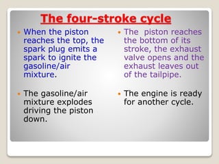
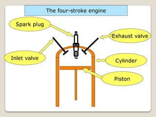
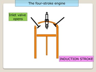
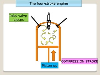
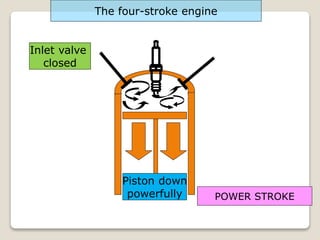
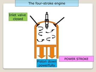
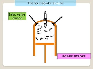
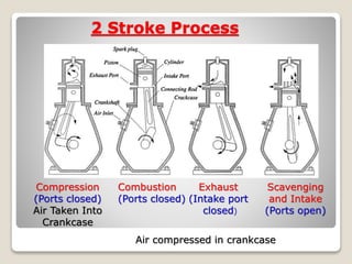
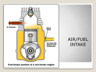
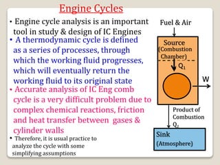
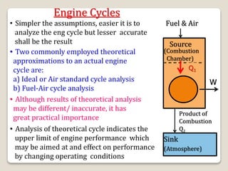
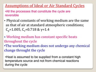
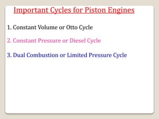
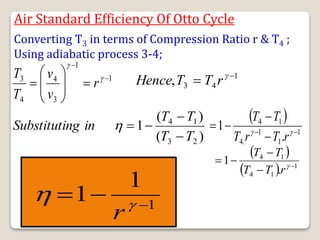
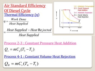
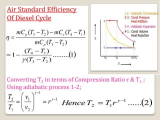
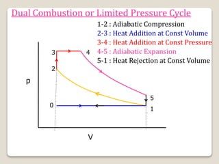
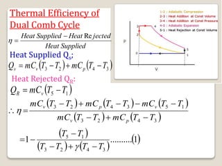
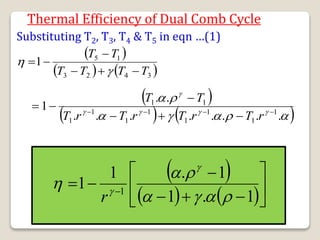
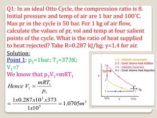
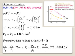
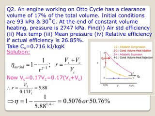
4 Processes Cycle
Intake Stroke
Intake valve
opens,
admitting fuel
and air. Exhaust
valve closed for
most of stroke
Compression
Stroke
Both valves closed,
Fuel/air mixture is
compressed by
rising piston. Spark
ignites mixture near
end of stroke.
Intake
Manifold
Spark
Plug
Cylinder
Piston
Connecting
Rod Crank
Power Stroke
Fuel-air mixture burns,
increasing temp and
pressure, expansion of
combustion gases
drives piston down.
Both valves closed,
exhaust valve opens
near end of stroke
1 2 3
4
Exhaust Stroke
Exhaust valve
open, exhaust
products are
displaced from
cylinder. Intake
valve opens near
end of stroke.
Crankcase
Exhaust
Manifold
Exhaust Valve
Intake Valve
The four-stroke cycle
The four stroke
combustion cycle
consists of:
◦ 1. Intake
◦ 2. Compression
◦ 3. Combustion
◦ 4. Exhaust
The four-stroke cycle
The piston starts at
the top, the intake
valve opens and the
piston moves down
to let the engine
take in a full
cylinder of air and
gasoline during the
intake stroke
The piston then
moves up to
compress the
air/gasoline
mixture. This
makes the
explosion more
powerful.
The four-stroke cycle
 When the piston
reaches the top, the
spark plug emits a
spark to ignite the
gasoline/air
mixture.
 The gasoline/air
mixture explodes
driving the piston
down.
 The piston reaches
the bottom of its
stroke, the exhaust
valve opens and the
exhaust leaves out
of the tailpipe.
 The engine is ready
for another cycle.
Spark plug
Inlet valve
Exhaust valve
Cylinder
Piston
The four-stroke engine
Inlet valve
opens
INDUCTION STROKE
The four-stroke engine
Inlet valve
open
Piston down
INDUCTION STROKE
The four-stroke engine
Inlet valve
open
Piston down
INDUCTION STROKE
The four-stroke engine
Air/Fuel Mixture In
Inlet valve
closes
COMPRESSION STROKE
The four-stroke engine
Piston up
Inlet valve
closed
COMPRESSION STROKE
The four-stroke engine
Piston up
Inlet valve
closed
POWER STROKE
The four-stroke engine
BANG
Inlet valve
closed
POWER STROKE
The four-stroke engine
Piston down
powerfully
Inlet valve
closed
POWER STROKE
The four-stroke engine
Piston down
powerfully
Inlet valve
closed
POWER STROKE
The four-stroke engine
Inlet valve
closed
EXHAUST STROKE
The four-stroke engine
Exhaust valve
open
Inlet valve
closed
EXHAUST STROKE
The four-stroke engine
Exhaust valve
open
Piston up
Exhaust gases
out
Inlet valve
closed
EXHAUST STROKE
The four-stroke engine
Exhaust valve
open
Piston up
Exhaust gases
out
Inlet valve
opens
INDUCTION STROKE
The four-stroke engine
Exhaust valve
closed
And so the
cycle
continues!!
Four Strok Diesel Engine
Department of Mechanical Engg.
22
Air Standard Cycles & Fuel - Air - Cycles
TWO STROKE
OPERATION
2 Stroke Process
Compression
(Ports closed)
Air Taken Into
Crankcase
Combustion
(Ports closed)
Exhaust
(Intake port
closed)
Air compressed in crankcase
Scavenging
and Intake
(Ports open)
AIR/FUEL
INTAKE
COMPRESSION
COMBUSTION
&
EXHAUST
Engine Terminology
Dead Centre
TDC
BDC
Engine Terminology
More Terminology
Terminology
 Bore = d
 Piston Area
 Stroke = s
 Displacement (Stroke/Swept)
volume(Vs) =As =
 Engine Capacity (Cubic Capacity)
 Clearance volume = Vc
 Compression ratio = r








4
d
s
2

TDC
BDC
V
V

r = Vs + Vc
Vc
Engine Cycles
• Engine cycle analysis is an important
tool in study & design of IC Engines
• A thermodynamic cycle is defined
as a series of processes, through
which the working fluid progresses,
which will eventually return the
working fluid to its original state
• Accurate analysis of IC Eng comb
cycle is a very difficult problem due to
complex chemical reactions, friction
and heat transfer between gases &
cylinder walls
• Therefore, it is usual practice to
analyze the cycle with some
simplifying assumptions
Fuel & Air
Source
(Combustion
Chamber)
Q1
W
Product of
Combustion
Q2
Sink
(Atmosphere)
Engine Cycles
• Simpler the assumptions, easier it is to
analyze the eng cycle but lesser accurate
shall be the result
• Two commonly employed theoretical
approximations to an actual engine
cycle are:
a) Ideal or Air standard cycle analysis
b) Fuel-Air cycle analysis
• Although results of theoretical analysis
may be different/ inaccurate, it has
great practical importance
• Analysis of theoretical cycle indicates the
upper limit of engine performance which
may be aimed at and effect on performance
by changing operating conditions
Fuel & Air
Source
(Combustion
Chamber)
Q1
W
Product of
Combustion
Q2
Sink
(Atmosphere)
Assumptions of Ideal or Air Standard Cycles
Air standard cycles are defined as cycles using a perfect
gas as the working fluid/ medium.
• Working medium is AIR and behaves like ideal/
perfect gas throughout ( follows the Law pV=mRT )
• Working fluid is a fixed mass of air either contained
in a closed system or flowing at a constant rate
round a closed circuit
Air is invariably used as the working fluid in IC Engines
and assumed to behave as a perfect gas
Following simplifying assumptions are made in the
analysis of air standard cycles:
Assumptions of Ideal or Air Standard Cycles
• Working medium has constant specific heats
throughout the cycle
•The working medium does not undergo any chemical
change throught the cycle
• Physical constants of working medium are the same
as that of air at standard atmospheric conditions;
Cp=1.005, Cv=0.718 & γ=1.4
•All the processes that constitute the cycle are
reversible
•Heat is assumed to be supplied from a constant high
temperature source and not from chemical reactions
during the cycle
Assumptions of Ideal or Air Standard Cycles
• Compression & Expansion processes are reversible
adiabatic (Isentropic); (no heat transfer)
• All dissipative effects like friction, viscosity etc, are
neglected
• Kinetic & PE of the working fluid are neglected
• Heat addition & rejection processes take place in
reversible manner and if required, instantaneously
(at constant volume)
• Some heat is assumed to be rejected to a constant
temperature sink during the cycle
Useful Thermodynamic Relations (Perfect Gas)
• pV = mRT or pv = RT and p1V1/T1 = p2V2/T2
• Cp – Cv = R
• For reversible adiabatic process : pVγ = Const
• For Const Volume(Isochoric) process: p/T = Const
(Gay Lussac Law)
• For Const Pressure (Isobaric) process : V/T = Const
(Charle’s Law)
• For Const Temp (Isothermal) process: pV = Const
(Boyle’s Law)
• In Compression process, if p1, V1 and T1 represent
initial conditions & p2, V2 and T2 the final conditions;
n
n
n
p
p
V
V
T
T
1
1
2
1
2
1
1
2
















Where n=γ for reversible
adiabatic (isentropic)
process
Some Useful Standard Values for Perfect Gas/Air
Specific Heat at Const Pressure Cp=1.005 kJ/kgK
Specific Heat at Const Volume Cv=0.718 kJ/kgK
Gas Constant R=0.287 kJ/kgK
Ratio of Cp/Cv=γ=1.4 (Constant)
Pascal Pa=N/m2
1 bar = 105 Pa =105 N/m2 =100 kPa =1.03 kg/cm2
1 MPa = 106 Pa = 10 bar
Pressure:
Volume:
1 lit = 1000cc = 10-3m3
Important Cycles for Piston Engines
1. Constant Volume or Otto Cycle
2. Constant Pressure or Diesel Cycle
3. Dual Combustion or Limited Pressure Cycle
p
V
1
2
3
4
Idealized Otto /Const Volume Cycle
0
1-2 : Adiabatic Compression
2-3 : Const Volume Heat Addition
3-4 : Adiabatic Expansion
4-1 : Const Volume Heat Rejection
V1/V4
V2/V3
Air Standard Efficiency
Of Otto Cycle
Thermal Efficiency (η)
Supplied
Heat
Done
Work


Supplied
Heat
jected
Heat
Supplied
Heat Re


Process 2-3 : Constant Volume Heat Addition
)
( 2
3 T
T
mC
Q v
s 

Process 4-1 : Constant Volume Heat Rejection
)
( 1
4 T
T
mC
Q v
R 

Air Standard Efficiency Of Otto Cycle
Hence ;
)
(
)
(
)
(
2
3
1
4
2
3
T
T
mC
T
T
mC
T
T
mC
v
v
v






)
(
)
(
1
2
3
1
4
T
T
T
T




r
v
v
Ratio
Expansion
v
v
Ratio
n
Compressio
Now 

3
4
2
1
Converting T2 in terms of Compression Ratio r & T1 ;
Using adiabatic process 1-2;
1
1
2
1
1
2 










 

r
v
v
T
T 1
1
2
, 
 
r
T
T
Hence
Air Standard Efficiency Of Otto Cycle
)
(
)
(
1
2
3
1
4
T
T
T
T
in
ng
Substituti





Converting T3 in terms of Compression Ratio r & T4 ;
Using adiabatic process 3-4;
1
1
3
4
4
3 










 

r
v
v
T
T 1
4
3
, 
 
r
T
T
Hence
 
1
1
1
.
4
1
4
.
1 




 

r
T
r
T
T
T
 
  1
1
4
1
4
.
1 



 
r
T
T
T
T
1
1
1 

 

r
Air Standard Efficiency of Otto Cycle
Real and Idealized Cycle
Ideal Diesel /Constant Pressure Cycle
Assumptions of Ideal Diesel Cycle
• Working fluid/substance is AIR
• Air behaves like an ideal/perfect gas & its specific
heats are constant and do not vary with temp
• Heat addition(2-3) takes place at const pr (unlike
Otto Cycle) & heat rejection (4-1) at constant volume
• Suction(0-1) & exhaust(1-0) strokes take place at
atmospheric pressure (Constant Pressure)
• Compression(1-2) & Expansion(3-4) processes are
adiabatic reversible (Isentropic)
• All dissipative effects like friction, viscosity etc, are
neglected
• All 4 strokes take place during 180° of crank rotation
• Valves open and close at TDC & BDC
Some Important Aspects of Diesel Cycle
• During heat addition at constant pressure, air
expands from volume V2 to V3 doing some work as
fuel injection commences at V2 and cuts off at V3 ,
called Cut Off Point
• In actual engine, heat addition takes place in the
form of injection of fuel, which self-ignites due to
high temp caused by high CR and burns at constant
pressure as piston moves down
• The volume ratio V3/V2 is called cut off ratio and is
denoted by ρ
• Compression Ratio and Expansion Ratio are not
equal in diesel cycle (unlike in Otto Cycle)
Air Standard Efficiency
Of Diesel Cycle
Thermal Efficiency (η)
Supplied
Heat
Done
Work


Supplied
Heat
jected
Heat
Supplied
Heat Re


Process 2-3 : Constant Pressure Heat Addition
)
( 2
3 T
T
mC
Q p
s 

Process 4-1 : Constant Volume Heat Rejection
)
( 1
4 T
T
mC
Q v
R 

Air Standard Efficiency
Of Diesel Cycle
)
(
)
(
)
(
2
3
1
4
2
3
T
T
mC
T
T
mC
T
T
mC
p
v
p






 
1
.........
)
(
)
(
1
2
3
1
4
T
T
T
T





Converting T2 in terms of Compression Ratio r & T1 ;
Using adiabatic process 1-2;
1
1
2
1
1
2 










 

r
v
v
T
T
 
2
......
1
1
2

 
r
T
T
Hence
Air Standard Efficiency
Using Constant Pressure
process 2-3 (V/T=C);
2
2
3
3
2
2
3
3
xT
V
V
T
T
V
T
V



 
3
.....
.
, 1
.
1
3

 
 r
T
T
Hence
Using Adiabatic process 3-4;
 
4
.....
1
4
3
3
4
1
4
3
3
4























V
V
T
T
V
V
T
T
r
r
x
V
V
x
V
V
V
V
ng
Manipulati

 


1
1
2
2
3
4
3
Air Standard Efficiency
We have eqn (4);
 
5
...
1
3
1
4
3
3
4






















r
T
V
V
T
T
Substituting T3 from eqn (3)
in eqn (5), we have;
 
6
.......
.
.
. 1
1
1
1
1
4 T
r
r
T
T 





 
 


Substituting T2, T3 & T4 in eqn (1), we have:
 
 
1
1
1
1
1
1
2
3
1
4
.
.
.
1
)
(
)
(
1 








 







r
T
r
T
T
T
T
T
T
T
 









 
1
1
1
1 1






r
Air Standard Efficiencies : Otto & Diesel Cycles
 








 
1
1
1
1 1






r
1
1
1 

 

r
Otto Cycle:
Diesel Cycle:
• In Diesel Cycle, bracketed
term is always > 1, hence
η for diesel cycle will
always be lower than Otto
for same CR
• With increase in CR, η initially increases at faster rate
• Diesel engs operate at much higher CR as compared
to petrol engs, hence η for diesel eng is actually higher
• η decreases as Cut off ρ increases
Dual Combustion or Limited Pressure Cycle
p
V
0
1
2
3 4
5
1-2 : Adiabatic Compression
2-3 : Heat Addition at Const Volume
3-4 : Heat Addition at Const Pressure
4-5 : Adiabatic Expansion
5-1 : Heat Rejection at Const Volume
Thermal Efficiency of
Dual Comb Cycle
Supplied
Heat
jected
Heat
Supplied
Heat Re



Heat Supplied Qs;
   
3
4
2
3 T
T
mC
T
T
mC
Q p
v
s 



Heat Rejected QR:
 
1
5 T
T
mC
Q v
R 

     
   
3
4
2
3
1
5
3
4
2
3
T
T
mC
T
T
mC
T
T
mC
T
T
mC
T
T
mC
p
v
v
p
v










 
   
 
1
..........
1
3
4
2
3
1
5
T
T
T
T
T
T







Thermal Efficiency of
Dual Comb Cycle
Using Adiabatic
Compression Process (1-2);
 
2
......
. 1
1
2
1
2
1
1
2 











 

r
T
T
V
V
T
T
Using Const Vol Process(2-3) (p/T=C):





2
3
2
3
2
2
3
3
p
p
T
T
T
p
T
p
 
3
.........
.
. 1
1
2
3 
  


 r
T
T
T
Thermal Efficiency of
Dual Comb Cycle
Using Const Pressure
Process (1-2): (V/T=C);
3
4
3
4
3
3
4
4
.
V
V
T
T
T
V
T
V



Using Adiabatic Expansion (4-5):
1
5
4
4
5











V
V
T
T
 
4
.........
.
.
. 1
1
4 

 

 r
T
T
 
2
3
1
3
3
4
1
4
5
4 1
. V
V
r
V
V
x
V
V
V
V
V
V
Now 


 

 
5
.....
.
.
.
.
.
.
. 1
1
1
1
1
3
1
4
5
y
T
r
r
T
r
T
r
T
T 






































Thermal Efficiency of Dual Comb Cycle
Substituting T2, T3, T4 & T5 in eqn …(1)
 
   
3
4
2
3
1
5
1
T
T
T
T
T
T








 
   












.
.
.
.
.
.
.
.
.
.
1 1
1
1
1
1
1
1
1
1
1










r
T
r
T
r
T
r
T
T
T
 
   










 
1
.
1
1
.
1
1 1









r
Theoretical/ Air Std Efficiencies
Otto Cycle: 1
1
1 

 

r
Diesel Cycle:  








 
1
1
1
1 1






r
Dual Cycle:
 
   










 
1
.
1
1
.
1
1 1









r
Numericals
Q.1An engine working on Otto cycle has the
following conditions: pressure at the beginning of
compression is 1bar and pressure at the end of
compression is 11 bar. Calculate the compression
ratio and air-standard efficiency of the engine.
Assume γ=1.4( Ans:5.54 , 49.6%)
Q.2 In an engine working on ideal Otto cycle the
temperature at the beginning and end of
compression are 373 0C and 500 0C. Find the
compression ratio and the air standard efficiency of
the engine (Ans:5.66, 50%)
Q1: In an ideal Otto Cycle, the compression ratio is 8.
Initial pressure and temp of air are 1 bar and 100˚C.
Max pr in the cycle is 50 bar. For 1 kg of air flow,
calculate the values of pr, vol and temp at four salient
points of the cycle. What is the ratio of heat supplied
to heat rejected? Take R=0.287 kJ/kg; γ=1.4 for air.
Solution:
Point 1: p1=1bar; T1=373K;
V1=?
We know that p1V1=mRT1
3
5
3
1
1
1
0705
.
1
10
1
373
10
287
.
0
1
m
x
x
x
x
p
mRT
V
Hence



Solution (contd):
Point 2: (1-2 adiabatic compn)














2
1
1
2
2
2
1
1
V
V
p
p
V
p
V
p
bar
x
p 38
.
18
8
1 4
.
1
2 


3
1
2
2
1
1338
.
0
8
0705
.
1
8
8
m
V
V
r
V
V
Now






2
2
2
1
1
1
T
V
p
T
V
p

K
x
x
x
xT
V
p
V
p
T 8
.
856
373
0705
.
1
1
1338
.
0
38
.
18
1
1
1
2
2
2 



Solution (contd):
Point 3:(2-3 const vol process)
?
;
50
;
1338
.
0
3
3
3
2
3




T
bar
p
m
V
V






 Const
T
p
ocess
Volume
t
Cons
For
Pr
tan
K
x
T
Hence
xT
p
p
T
T
p
T
p
8
.
2330
8
.
856
38
.
18
50
2
3
2
3
3
2
2
3
3





Solution (contd):
Point 4:(3-4 Adiabatic process)
bar
x
p
V
V
p
V
V
p
p
V
p
V
p
72
.
2
8
1
50
4
.
1
4
1
2
3
4
3
3
4
4
4
3
3

































K
x
xT
p
p
T
Hence
T
p
T
p
process
volume
t
cons
From
6
.
1014
373
1
72
.
2
)
1
4
(
tan
1
1
4
4
1
1
4
4





3
1
4 0705
.
1 m
V
V 

Solution (contd):
 
2
3 T
T
mC
Q
Supplied
Heat v
S 

kg
kJ
R
C
OR
C
R
R
C
C
that
know
we
C
find
To
v
v
v
p
v
/
718
.
0
1
4
.
1
287
.
0
1
1
:
,












 
  kJ
x
Q
T
T
mC
Q
jected
Heat
R
v
R
7
.
460
373
6
.
1014
718
.
0
1
Re 1
4





  kJ
x
Q
Hence S 4
.
1062
8
.
856
8
.
2330
718
.
0
1 


3
.
2
7
.
460
4
.
1062
Re


jected
Heat
Supplied
Heat
Q2. An engine working on Otto Cycle has a clearance
volume of 17% of the total volume. Initial conditions
are 93 kPa & 30˚C. At the end of constant volume
heating, pressure is 2747 kPa. Find(i) Air std efficiency
(ii) Max temp (iii) Mean pressure (iv) Relative efficiency
if actual efficiency is 26.85%.
Take Cv=0.716 kJ/kgK
Solution:
c
c
s
Std
air
V
V
V
r
r



 
;
1
1 1


Now Vc=0.17V1=0.17(Vs+Vc)
88
.
5
17
.
0 1
1



V
V
r
%
76
.
50
5076
.
0
88
.
5
1
1 1
4
.
1
or



 

Solution (Contd):
Max Temp T3=?
1
2
1
1
2
),
2
1
(
Pr












V
V
T
T
ocess
From
K
x
V
V
T
T 45
.
615
88
.
5
303 1
4
.
1
1
2
1
1
2 










 
















2
1
1
2
2
2
1
1
V
V
p
p
V
p
V
p   kPa
p 73
.
1110
88
.
5
93
4
.
1
2 


2
2
3
3
:
)
3
2
(
Pr
T
p
T
p
ocess
Vol
Const
For 

K
x
x
x
xT
p
p
T 36
.
1520
10
73
.
1110
45
.
615
10
2747
3
3
2
2
3
3 



Solution (Contd):
2
1
/
V
V
WD
Volume
Stroke
Cycle
Done
Work
Pmean



S
Q
x
WD 

 
kg
kJ
x
T
T
mC
Q v
S
/
9
.
647
45
.
615
36
.
1520
716
.
0
1
)
( 2
3





WD=η x Qs
WD=647.9x0.5076=328.88kJ/kg
To find out Stroke Vol (V1-V2) ; we have V1/V2=5.88
V1 can be found out from p1V1=mRT1 taking m=1kg
Hence V1=(1x0.287x303)/93=0.935m3/kg
Therefore, V2=V1/5.88=0.935/5.88=0.159m3/kg
Solution (Contd):
2
1
/
V
V
WD
Volume
Stroke
Cycle
Done
Work
Pmean



kPa
Pmean 7
.
423
159
.
0
935
.
0
88
.
328



%
89
.
52
76
.
50
85
.
26
Re



Efficiecy
Std
Air
Efficiency
Actual
Efficiency
lative R

Q3. An air standard diesel cycle has a compression
ratio of 14. Pressure at the beginning of compn stroke
is 1 bar and temp 27˚C. Max temp in the cycle is
2500˚C. Determine the thermal efficiency and mean
Effective pressure.
Solution:
Supplied
Heat
jected
Heat
Supplied
Heat Re



Qs=mCp(T3-T2) & QR=mCv(T4-T1)
)
(
)
(
)
(
2
3
1
4
2
3
T
T
mC
T
T
mC
T
T
mC
p
v
p






 
2
3
1
4
1
T
T
T
T






Since T1 & T3 are given, T2 & T4
are required to be found out ?
Solution (Contd):
K
x
V
V
T
T
ocess
For 864
14
300
);
2
1
(
Pr 1
4
.
1
1
2
1
1
2 










 


2
2
3
3
:
)
3
2
(
Pr
Pr
tan
T
V
T
V
ocess
essure
t
Cons
For 

21
.
3
864
2773
2
3
2
3



T
T
V
V
1
4
3
3
4
);
4
3
(
Pr












V
V
T
T
ocess
Adiabatic
For
1
1
2
2
3
3
1
4
2
2
3
3
4






















V
V
x
V
V
T
V
V
x
V
V
T
T
K
x
T 5
.
1538
14
1
21
.
3
2773
4
1
4
.
1










 
2
3
1
4
1
T
T
T
T






Solution (Contd):
 
 
%
66
.
53
5366
.
0
864
2773
4
.
1
300
5
.
1538
1 or





;
/
Volume
Stroke
Cycle
Done
Work
Pmean 












1
2
1
2
1 1
V
V
V
V
V
Vol
Stroke
1
1
1
1; mRT
V
p
have
we
V
out
find
To 
kg
m
x
x
x
p
RT
V
air
of
kg
Taking /
861
.
0
10
1
300
10
287
.
0
,
1 3
5
3
1
1
1 


3
1
2
1 7995
.
0
14
1
1
861
.
0
1
, m
V
V
V
Vol
Stroke
Hence 


















Solution (Contd):
;
/
Volume
Stroke
Cycle
Done
Work
Pmean 
 
Volume
Stroke
T
T
C
T
T
C v
p )
( 1
4
2
3 



   
bar
x
x
x
86
.
12
10
7995
.
0
300
5
.
1538
10
718
.
0
.
0
864
2773
10
005
.
1
5
3
3





Q4. An oil engine works on the ideal diesel cycle.
CR is 18 and constant pr energy addition ceases at
10% of stroke. Intake conditions are 1 bar and 20˚C.
Determine (a) Max temp and pressure in the cycle
(b) Thermal efficiency of the engine
Solution: Max pressure p3=p2 = ? Max Temp T3=?
 








 
1
1
1
1 1






r
Efficiency
Thermal th
r=V1/V2=18 (given) ρ=V3/V2=?
Let Clearance Volume V2=1
Then, V1 will be 18
Hence stroke vol=V1-V2=17
Now, 10% of stroke vol
=17x0.1=1.7
Solution (Contd):
 








 
1
1
1
1 1






r
Efficiency
Thermal th
Therefore, ρ=V3/V2=2.7/1=2.7
Hence, V3=1+1.7=2.7
 
%
60
6
.
0
1
7
.
2
4
.
1
1
7
.
2
18
1
1
4
.
1
1
4
.
1
or
th 









 

bar
x
V
V
p
p
process
adiabatic
From
2
.
57
18
1
:
)
2
1
(
4
.
1
2
1
1
2 












K
x
V
V
T
T 931
18
293 1
4
.
1
1
2
1
1
2 









 


Solution (Contd):
3
3
3
2
2
2
:
)
3
2
(
T
V
p
T
V
p
process
for
law
gas
perfect
From


K
x
V
p
V
p
x
T
T 7
.
2513
7
.
2
931
2
2
3
3
2
3 



Q5. A dual comb cycle has an adiabatic CR of 15.
Conditions at commencement of compression are
1 bar, 25˚C and 0.1 m3. Max pr in the cycle is 65 bar
and max temp 1500˚C. Calculate pr, vol and temp at
the corners and thermal efficiency of the cycle.
Solution:
Point 1: p1=1bar; V1=0.1m3
T1=25+273=298K
Point 2:
p2=p1(V1/V2)γ
=1x151.4=44.3 bar
T2=T1(V1/V2)γ-1
=298x150.4=880K
V1/V2=15
V2=0.1/15=0.0067m3
Solution (Contd):
Point 3: p3=65 bar
Point 4: p4=p3 =65 bar (given)
T3/T2 =p3/p2 T3=T2(p3/p2)
T3=880x(65/44.3)=1291.2K
V3 =V2=0.0067m3
T4=1500+273=1773K (given)
V4/V3=T4/T3
Hence V4=V3xT4/T3
V4=0.0067x1773/1291.2=0.0092m3
Point 5: V5=V1=0.1m3
p5=p4(V4/V5)γ =65(0.0092/0.1)1.4 =2.3 bar
T5=T4(V4/V5)γ-1 =1773(0.0092/0.1)0.4=682.7K
Solution (Contd):
 
   
3
4
2
3
1
5
1
T
T
T
T
T
T
Efficiency
Thermal th








 
   
3
4
2
3
1
5
1
T
T
T
T
T
T
th








 
   
2
.
1291
1773
4
.
1
880
2
.
1291
298
7
.
682
1






%
5
.
64
645
.
0
354
.
0
1 or
th 



Fuel Air Cycles
• Air std cycle has highly simplified approximations
• Therefore, estimate of engine performance is much
higher than the actual performance
• For example, actual indicated thermal efficiency of
a petrol engine for CR 7, is around 30% whereas
air std efficiency is around 55%.
• This large difference is due to non-instantaneous
burning of charge, incomplete combustion and
largely over simplification in using values of
properties of working fluid for analysis
• In std air cycle, it was assumed that working fluid
was air, which behaves like perfect gas and had
constant specific heats
Fuel Air Cycles
• In actual engine , working fluid is not air but a
mixture of air, fuel and residual gases
• Also, specific heats of working fluid are not constant
but increase as the temp rises
• And, products of combustion are subjected to
dissociation at high temperatures
• Engine operation is not frictionless
Theoretical Fuel-Air Cycles
Cycles, which take in to account the variations
of specific heats, effects of molecular structure,
effects of composition of mixture of fuel, air &
residual gases approximating to working substance,
are called Fuel-Air Cycles
Fuel-air cycles largely take the following in to
consideration:
• Actual composition of cylinder gases i,e. fuel, air,
water vapor and residual gases
• Variation (increase) of specific heats with temp
Specific heats vary (increase) with increase in temp
(hence γ = Cp/Cv ↓with ↑T)
Cp = a + bT + cT2 + dT3
Cv = a1 + bT + cT2 + dT3; a1 > a
Theoretical Fuel-Air Cycle
• After combustion process, mixture is in chemical
equilibrium (No dissociation )
• Intake and exhaust processes take place at
atmospheric pressure
• Compression & expansion processes are adiabatic
without friction
• In case of Otto Cycle, mixture of air & fuel is
homogenous and it burns at constant volume
• Change in KE is negligible
• No heat exchange between gases and cylinder walls
• Mixture of fuel & air (A/F ratio)
Theoretical Fuel-Air Cycle
1. Effect of Composition of Fuel and Air (A/F Ratio):
• Leaner mixture has higher thermal efficiency
• Richer mixture will have lower efficiency as unburnt
fuel will go to exhaust
• Efficiency increases with CR
 













1
1
1
1
1
1
1
1








r
OR
r
diesel
otto
V
p
1
2
3
4
2’
3’
4’
4’’
Actual Cycle 1-2’-3’-4’’
2. Effect of Variation Specific Heats :
Ideal Otto Cycle 1-2-3-4
Theoretical Fuel-Air Cycle
2. Effect of Variation Specific Heats :
• Cp=a+bT+cT2 & Cv=a1+bT+cT2
• During adiabatic compn process 1-2, as the temp
increases, Cp & Cv increase and γ decreases
'
, 2
1
2
1
1
2 T
temp
to
down
comes
V
V
T
T
temp
Therefore











• During process 2-3, for a
given heat supplied Qs,
temp T3 will lower down
to T3’ as per the expression
Qs=mCv(T3-T2’)
Qs
Theoretical Fuel-Air Cycle
2. Effect of Variation Specific Heats (Contd) :
• And, therefore, process 3-4 will now become 3’-4’
• But process 3’-4’ represents process with const γ.
Since eng is in expansion stroke, the temp of gases
decreases, Cp & Cv decrease and hence γ increases
'
'
'
'
'
' 4
1
3
1
1
2
3
1
4
3
3
4 T
to
decreases
r
T
V
V
T
V
V
T
T
Temp 





















 


• Hence, actual process
becomes 3’-4’’ from 3’-4’
• Therefore, actual cycle
becomes 1-2’-3’-4’’
although ideal Otto Cycle
was 1-2-3-4
Theoretical Fuel-Air Cycle
3. Effect of Molecular Structure :
• Pressure of gases in comb chamber is proportional to
number of moles for given temp and volume by the
relation pV=nR˚T; where n is the no of moles
• If the no of moles before and after combustion are
different, pressure will change accordingly
• Take example of combustion :
C + O2 = CO2
1 mole 1 mole 1 mole
2H2 + O2 = 2H2O
2 moles 1 mole 2 moles
Molecular
Contraction
C8H18 + 12.5O2 = 8CO2 + 9H2O
1 mole 12.5 moles 8 moles 9 moles
Molecular
Expansion
Theoretical Fuel-Air Cycle
• From the foregoing, it is clear that no of moles may
be more or less after the combustion
• This phenomenon is called molecular contraction or
molecular expansion
• Therefore, actual pressure in combustion chamber
will be different compared to theoretical cycle
• Actual pressure in combustion chamber shall be more
in case of molecular expansion and lesser in case of
molecular contraction compared to theoretical cycle
Theoretical Fuel-Air Cycle
4. Dissociation Losses:
• Products of combustion dissociate in to its
constituents at higher temp beyond 1000˚C
• Rate of dissociation increases with increase in temp
• Dissociation process absorbs heat energy from comb
gases being chemically endothermic reaction and
association releases energy being exothermic reaction
2CO2=2CO+O2 : (Dissociation) Endothermic Reaction
2CO+O2=2CO2 : (Association) Exothermic Reaction
Theoretical Fuel-Air Cycle
• This results in lowering of temp and hence pressure
which in turn reduces power output and thermal
efficiency
• However, at the end of expansion stroke,
temperatures become low and dissociated gases
start combining releasing heat energy.
• But, it is too late as most
of this heat energy is
carried away by exhaust
gases. This loss of power
is called dissociation loss
• Dissociation losses have
been shown in Fig
Actual/Real Fuel Air Cycles
Actual cycle efficiency is much lower than the air std
efficiency due to various losses occurring in actual
engine operation. These are:
1. Losses due to variation of specific heats with temp
2. Dissociation or chemical in-equilibrium losses
3. Time losses
4. Incomplete combustion losses
5. Direct heat losses from comb gases to surroundings
6. Exhaust blow-down losses
7. Pumping losses
8. Friction losses
Actual/Real Fuel-Air Cycle
• Working substance is mixture of fuel, air & residual
gases (not air or perfect gases)
• Specific heats vary (increase) with temp
(hence γ = Cp/Cv ↓with ↑T)
Cp = a + bT + cT2 + dT3
Cv = a1 + bT + cT2 + dT3; a1 > a
• Effect of molecular structure due to comb of fuel.
(Beyond 1000°C, products of comb dissociate &
absorb heat energy, thus lowering comb temp and
hence the power)
• Comb is not instantaneous (at const volume) as
piston continuously keeps moving resulting in time
losses
• Heat addition is not from reservoir but due to comb
of fuel, which alters composition of working fluid
Actual/Real Fuel-Air Cycle
• Compression & Expansion processes are polytropic
due to direct heat transfer to surroundings
• Opening and closing of valves are not
instantaneous. All 4 strokes do not take place in
180° crank rotation. Early opening of exhaust valve
causes blow down losses
• Suction stroke takes place below atmospheric
pressure and exhaust stroke above atm pressure
(Pumping losses)
• Thus, work developed in actual cycle is much less
than the theoretical cycle
• Friction losses also take place
Losses In Actual Cycle Other Than Fuel-Air Cycle
1. Time Losses:
• Work developed in actual
cycle is much less than
theoretical cycle as
shown in Fig (Area
enclosed by Blue Curve)
• Due to this time lag, actual max pr in comb chamber
lowers down to point x.
• In ideal cycles, heat addition is assumed at constant
volume but actually, combustion takes some finite
time while piston continues to move (30-40˚rotation
of crank shaft)
• Loss of work represents
time losses
Losses In Actual Cycle Other Than Fuel-Air Cycle
2. Heat Losses:
• Due to this, lot of work is lost
• There is considerable quantity of heat loss during
combustion and expansion processes
• Ideal Compression and Expansion processes are
assumed to be adiabatic but in actual processes,
heat transfer does take place from working fluid to
cylinder walls
• These work losses are called Heat Losses
Losses In Actual Cycle Other Than Fuel-Air Cycle
3. Exhaust Blow-down Losses:
• But due to this, lot of heat energy is carried away
by exhaust gases resulting in to loss of work
• In ideal cycle, exhaust valve is assumed to open at
BDC, when exhaust stroke starts but in actual cycle,
it opens 30 to 40˚ before BDC in power stroke itself
• This helps in reducing pressure in the cylinder during
exhaust stroke, so that work required to push out
exhaust gases, reduces
• This work losses are called Exhaust Blow-down Losses
Losses In Actual Cycle Other Than Fuel-Air Cycle
4. Pumping Losses:
• In ideal cycle, suction and exhaust processes are
assumed to be taking place at atmospheric pressure
• But in actual cycle, suction is carried out below and
exhaust above atm pressures and for these
operations, work is required to be done on gases
which comes from actual
work developed, thus
reducing over all power
output
• These work losses are
called Pumping losses
(shown in pink in Fig)
Losses In Actual Cycle Other Than Fuel-Air Cycle
5. Friction Losses:
• All this comes from power developed by the engine,
thus reducing actual power out put
• In ideal cycle, engine operation is considered
frictionless but in actual it is not so.
• Friction losses do occur between sliding or rotating
components like piston rings and cylinder walls,
bearings etc and it increases rapidly with speed of
the engine. Also, power is required to run various
auxiliary equipment like fans, pumps etc
• These power losses are called Friction Losses
Real/
Actual
Otto Cycle
Valve Timings : 4 Stroke SI Engine
IVO
IVC
TDC
BDC
EVC
EVO
Suction
Stroke
Power/
Expansion
Stroke
Exhaust
Stroke
Compression
Stroke
10°
20°
25°
20°
Ign Adv
Valve Timings : 4 Stroke CI Engine
IVO
IVC
TDC
BDC
EVC
EVO
Suction
Stroke
Power/
Expansion
Stroke
Exhaust
Stroke
Compression
Stroke
10°- 25°
10°-15°
45°
20°- 30°
FIC FIS
15° 25°
patm
Exhaust
Suction
p
V
Pumping Losses
p
V
1
2
3
4
0
1-2 : Adiabatic Compression
2-3 : Const Volume Heat Addition
3-4 : Adiabatic Expansion
4-1 : Const Volume Heat Rejection
V1/V4
V2/V3
QS
QR
Air Standard Efficiency Of Otto Cycle
100
80
60
40
20
0
0 4 8 12 16 18 20 24 26
Compression Ratio
η%
γ=1.4
Assignment No 1
1. Explain working of 2 Stroke SI & CI engines
2. Compare 2 Stroke & 4 Stroke Engines
3. Compare SI & CI engines
4. Draw port timings for 2 Stroke & valve timings
for 4 Stroke both for SI & CI Engines
5. What is fuel-air cycle? Write assumptions.
Explain effects of variation of sp heat, molecular
structure, dissociation losses and A/F ratio
6. Explain following losses in Actual Fuel-Air Cycle:
- Time losses
- Heat losses
- Exhaust blow down losses
- Pumping losses
p
V
0 1
2 3
4
Ideal Diesel / Constant Pressure Cycle
1-2 : Adiabatic Compression
2-3 : Const Pressure Heat Addition
3-4 : Adiabatic Expansion
4-1 : Const Vol Heat Rejection
V1/V4
V2 V3
100
80
60
40
20
0
0 4 8 12 16 18 20 24 26
Compression Ratio
η%
ρ=1(Otto Cycle)
ρ=2
ρ=4
ρ=3
p
V
0
1
2
3 4
5
1-2 : Adiabatic Compression
2-3 : Heat Addition at Const Volume
3-4 : Heat Addition at Const Pressure
4-5 : Adiabatic Expansion
5-1 : Heat Rejection at Const Volume
3 4 5 6 7 8 9
60
50
40
30
20
η
%
CR
Air Standard
120%
100%
80%
A/F
Leaner
Richer
BP
10 12 14 16 18 20
A/F Ratio
BP with no dissociation
BP with dissociation
Stoichiometric
Mixture
Specific Fuel Consumption
Dissociation
Losses
p
V
1
2
3’
3
4
4’
Ideal Cycle
Fuel-Air Cycle
Actual Cycle
x
y
Otto Cycle Time Losses

Air Std Cycles.pptx

  • 3.
    4 Processes Cycle IntakeStroke Intake valve opens, admitting fuel and air. Exhaust valve closed for most of stroke Compression Stroke Both valves closed, Fuel/air mixture is compressed by rising piston. Spark ignites mixture near end of stroke. Intake Manifold Spark Plug Cylinder Piston Connecting Rod Crank Power Stroke Fuel-air mixture burns, increasing temp and pressure, expansion of combustion gases drives piston down. Both valves closed, exhaust valve opens near end of stroke 1 2 3 4 Exhaust Stroke Exhaust valve open, exhaust products are displaced from cylinder. Intake valve opens near end of stroke. Crankcase Exhaust Manifold Exhaust Valve Intake Valve
  • 4.
    The four-stroke cycle Thefour stroke combustion cycle consists of: ◦ 1. Intake ◦ 2. Compression ◦ 3. Combustion ◦ 4. Exhaust
  • 5.
    The four-stroke cycle Thepiston starts at the top, the intake valve opens and the piston moves down to let the engine take in a full cylinder of air and gasoline during the intake stroke The piston then moves up to compress the air/gasoline mixture. This makes the explosion more powerful.
  • 6.
    The four-stroke cycle When the piston reaches the top, the spark plug emits a spark to ignite the gasoline/air mixture.  The gasoline/air mixture explodes driving the piston down.  The piston reaches the bottom of its stroke, the exhaust valve opens and the exhaust leaves out of the tailpipe.  The engine is ready for another cycle.
  • 7.
    Spark plug Inlet valve Exhaustvalve Cylinder Piston The four-stroke engine
  • 8.
  • 9.
    Inlet valve open Piston down INDUCTIONSTROKE The four-stroke engine
  • 10.
    Inlet valve open Piston down INDUCTIONSTROKE The four-stroke engine Air/Fuel Mixture In
  • 11.
    Inlet valve closes COMPRESSION STROKE Thefour-stroke engine Piston up
  • 12.
    Inlet valve closed COMPRESSION STROKE Thefour-stroke engine Piston up
  • 13.
    Inlet valve closed POWER STROKE Thefour-stroke engine BANG
  • 14.
    Inlet valve closed POWER STROKE Thefour-stroke engine Piston down powerfully
  • 15.
    Inlet valve closed POWER STROKE Thefour-stroke engine Piston down powerfully
  • 16.
  • 17.
    Inlet valve closed EXHAUST STROKE Thefour-stroke engine Exhaust valve open
  • 18.
    Inlet valve closed EXHAUST STROKE Thefour-stroke engine Exhaust valve open Piston up Exhaust gases out
  • 19.
    Inlet valve closed EXHAUST STROKE Thefour-stroke engine Exhaust valve open Piston up Exhaust gases out
  • 20.
    Inlet valve opens INDUCTION STROKE Thefour-stroke engine Exhaust valve closed
  • 21.
  • 22.
    Four Strok DieselEngine Department of Mechanical Engg. 22 Air Standard Cycles & Fuel - Air - Cycles
  • 23.
  • 24.
    2 Stroke Process Compression (Portsclosed) Air Taken Into Crankcase Combustion (Ports closed) Exhaust (Intake port closed) Air compressed in crankcase Scavenging and Intake (Ports open)
  • 25.
  • 26.
  • 27.
  • 28.
  • 29.
  • 30.
  • 31.
    Terminology  Bore =d  Piston Area  Stroke = s  Displacement (Stroke/Swept) volume(Vs) =As =  Engine Capacity (Cubic Capacity)  Clearance volume = Vc  Compression ratio = r         4 d s 2  TDC BDC V V  r = Vs + Vc Vc
  • 33.
    Engine Cycles • Enginecycle analysis is an important tool in study & design of IC Engines • A thermodynamic cycle is defined as a series of processes, through which the working fluid progresses, which will eventually return the working fluid to its original state • Accurate analysis of IC Eng comb cycle is a very difficult problem due to complex chemical reactions, friction and heat transfer between gases & cylinder walls • Therefore, it is usual practice to analyze the cycle with some simplifying assumptions Fuel & Air Source (Combustion Chamber) Q1 W Product of Combustion Q2 Sink (Atmosphere)
  • 34.
    Engine Cycles • Simplerthe assumptions, easier it is to analyze the eng cycle but lesser accurate shall be the result • Two commonly employed theoretical approximations to an actual engine cycle are: a) Ideal or Air standard cycle analysis b) Fuel-Air cycle analysis • Although results of theoretical analysis may be different/ inaccurate, it has great practical importance • Analysis of theoretical cycle indicates the upper limit of engine performance which may be aimed at and effect on performance by changing operating conditions Fuel & Air Source (Combustion Chamber) Q1 W Product of Combustion Q2 Sink (Atmosphere)
  • 35.
    Assumptions of Idealor Air Standard Cycles Air standard cycles are defined as cycles using a perfect gas as the working fluid/ medium. • Working medium is AIR and behaves like ideal/ perfect gas throughout ( follows the Law pV=mRT ) • Working fluid is a fixed mass of air either contained in a closed system or flowing at a constant rate round a closed circuit Air is invariably used as the working fluid in IC Engines and assumed to behave as a perfect gas Following simplifying assumptions are made in the analysis of air standard cycles:
  • 36.
    Assumptions of Idealor Air Standard Cycles • Working medium has constant specific heats throughout the cycle •The working medium does not undergo any chemical change throught the cycle • Physical constants of working medium are the same as that of air at standard atmospheric conditions; Cp=1.005, Cv=0.718 & γ=1.4 •All the processes that constitute the cycle are reversible •Heat is assumed to be supplied from a constant high temperature source and not from chemical reactions during the cycle
  • 37.
    Assumptions of Idealor Air Standard Cycles • Compression & Expansion processes are reversible adiabatic (Isentropic); (no heat transfer) • All dissipative effects like friction, viscosity etc, are neglected • Kinetic & PE of the working fluid are neglected • Heat addition & rejection processes take place in reversible manner and if required, instantaneously (at constant volume) • Some heat is assumed to be rejected to a constant temperature sink during the cycle
  • 38.
    Useful Thermodynamic Relations(Perfect Gas) • pV = mRT or pv = RT and p1V1/T1 = p2V2/T2 • Cp – Cv = R • For reversible adiabatic process : pVγ = Const • For Const Volume(Isochoric) process: p/T = Const (Gay Lussac Law) • For Const Pressure (Isobaric) process : V/T = Const (Charle’s Law) • For Const Temp (Isothermal) process: pV = Const (Boyle’s Law) • In Compression process, if p1, V1 and T1 represent initial conditions & p2, V2 and T2 the final conditions; n n n p p V V T T 1 1 2 1 2 1 1 2                 Where n=γ for reversible adiabatic (isentropic) process
  • 39.
    Some Useful StandardValues for Perfect Gas/Air Specific Heat at Const Pressure Cp=1.005 kJ/kgK Specific Heat at Const Volume Cv=0.718 kJ/kgK Gas Constant R=0.287 kJ/kgK Ratio of Cp/Cv=γ=1.4 (Constant) Pascal Pa=N/m2 1 bar = 105 Pa =105 N/m2 =100 kPa =1.03 kg/cm2 1 MPa = 106 Pa = 10 bar Pressure: Volume: 1 lit = 1000cc = 10-3m3
  • 40.
    Important Cycles forPiston Engines 1. Constant Volume or Otto Cycle 2. Constant Pressure or Diesel Cycle 3. Dual Combustion or Limited Pressure Cycle
  • 41.
    p V 1 2 3 4 Idealized Otto /ConstVolume Cycle 0 1-2 : Adiabatic Compression 2-3 : Const Volume Heat Addition 3-4 : Adiabatic Expansion 4-1 : Const Volume Heat Rejection V1/V4 V2/V3
  • 42.
    Air Standard Efficiency OfOtto Cycle Thermal Efficiency (η) Supplied Heat Done Work   Supplied Heat jected Heat Supplied Heat Re   Process 2-3 : Constant Volume Heat Addition ) ( 2 3 T T mC Q v s   Process 4-1 : Constant Volume Heat Rejection ) ( 1 4 T T mC Q v R  
  • 43.
    Air Standard EfficiencyOf Otto Cycle Hence ; ) ( ) ( ) ( 2 3 1 4 2 3 T T mC T T mC T T mC v v v       ) ( ) ( 1 2 3 1 4 T T T T     r v v Ratio Expansion v v Ratio n Compressio Now   3 4 2 1 Converting T2 in terms of Compression Ratio r & T1 ; Using adiabatic process 1-2; 1 1 2 1 1 2               r v v T T 1 1 2 ,    r T T Hence
  • 44.
    Air Standard EfficiencyOf Otto Cycle ) ( ) ( 1 2 3 1 4 T T T T in ng Substituti      Converting T3 in terms of Compression Ratio r & T4 ; Using adiabatic process 3-4; 1 1 3 4 4 3               r v v T T 1 4 3 ,    r T T Hence   1 1 1 . 4 1 4 . 1         r T r T T T     1 1 4 1 4 . 1       r T T T T 1 1 1      r
  • 45.
  • 46.
  • 48.
    Ideal Diesel /ConstantPressure Cycle
  • 49.
    Assumptions of IdealDiesel Cycle • Working fluid/substance is AIR • Air behaves like an ideal/perfect gas & its specific heats are constant and do not vary with temp • Heat addition(2-3) takes place at const pr (unlike Otto Cycle) & heat rejection (4-1) at constant volume • Suction(0-1) & exhaust(1-0) strokes take place at atmospheric pressure (Constant Pressure) • Compression(1-2) & Expansion(3-4) processes are adiabatic reversible (Isentropic) • All dissipative effects like friction, viscosity etc, are neglected • All 4 strokes take place during 180° of crank rotation • Valves open and close at TDC & BDC
  • 50.
    Some Important Aspectsof Diesel Cycle • During heat addition at constant pressure, air expands from volume V2 to V3 doing some work as fuel injection commences at V2 and cuts off at V3 , called Cut Off Point • In actual engine, heat addition takes place in the form of injection of fuel, which self-ignites due to high temp caused by high CR and burns at constant pressure as piston moves down • The volume ratio V3/V2 is called cut off ratio and is denoted by ρ • Compression Ratio and Expansion Ratio are not equal in diesel cycle (unlike in Otto Cycle)
  • 51.
    Air Standard Efficiency OfDiesel Cycle Thermal Efficiency (η) Supplied Heat Done Work   Supplied Heat jected Heat Supplied Heat Re   Process 2-3 : Constant Pressure Heat Addition ) ( 2 3 T T mC Q p s   Process 4-1 : Constant Volume Heat Rejection ) ( 1 4 T T mC Q v R  
  • 52.
    Air Standard Efficiency OfDiesel Cycle ) ( ) ( ) ( 2 3 1 4 2 3 T T mC T T mC T T mC p v p         1 ......... ) ( ) ( 1 2 3 1 4 T T T T      Converting T2 in terms of Compression Ratio r & T1 ; Using adiabatic process 1-2; 1 1 2 1 1 2               r v v T T   2 ...... 1 1 2    r T T Hence
  • 53.
    Air Standard Efficiency UsingConstant Pressure process 2-3 (V/T=C); 2 2 3 3 2 2 3 3 xT V V T T V T V      3 ..... . , 1 . 1 3     r T T Hence Using Adiabatic process 3-4;   4 ..... 1 4 3 3 4 1 4 3 3 4                        V V T T V V T T r r x V V x V V V V ng Manipulati      1 1 2 2 3 4 3
  • 54.
    Air Standard Efficiency Wehave eqn (4);   5 ... 1 3 1 4 3 3 4                       r T V V T T Substituting T3 from eqn (3) in eqn (5), we have;   6 ....... . . . 1 1 1 1 1 4 T r r T T             Substituting T2, T3 & T4 in eqn (1), we have:     1 1 1 1 1 1 2 3 1 4 . . . 1 ) ( ) ( 1                   r T r T T T T T T T              1 1 1 1 1       r
  • 55.
    Air Standard Efficiencies: Otto & Diesel Cycles             1 1 1 1 1       r 1 1 1      r Otto Cycle: Diesel Cycle: • In Diesel Cycle, bracketed term is always > 1, hence η for diesel cycle will always be lower than Otto for same CR • With increase in CR, η initially increases at faster rate • Diesel engs operate at much higher CR as compared to petrol engs, hence η for diesel eng is actually higher • η decreases as Cut off ρ increases
  • 56.
    Dual Combustion orLimited Pressure Cycle p V 0 1 2 3 4 5 1-2 : Adiabatic Compression 2-3 : Heat Addition at Const Volume 3-4 : Heat Addition at Const Pressure 4-5 : Adiabatic Expansion 5-1 : Heat Rejection at Const Volume
  • 57.
    Thermal Efficiency of DualComb Cycle Supplied Heat jected Heat Supplied Heat Re    Heat Supplied Qs;     3 4 2 3 T T mC T T mC Q p v s     Heat Rejected QR:   1 5 T T mC Q v R             3 4 2 3 1 5 3 4 2 3 T T mC T T mC T T mC T T mC T T mC p v v p v                   1 .......... 1 3 4 2 3 1 5 T T T T T T       
  • 58.
    Thermal Efficiency of DualComb Cycle Using Adiabatic Compression Process (1-2);   2 ...... . 1 1 2 1 2 1 1 2                r T T V V T T Using Const Vol Process(2-3) (p/T=C):      2 3 2 3 2 2 3 3 p p T T T p T p   3 ......... . . 1 1 2 3        r T T T
  • 59.
    Thermal Efficiency of DualComb Cycle Using Const Pressure Process (1-2): (V/T=C); 3 4 3 4 3 3 4 4 . V V T T T V T V    Using Adiabatic Expansion (4-5): 1 5 4 4 5            V V T T   4 ......... . . . 1 1 4       r T T   2 3 1 3 3 4 1 4 5 4 1 . V V r V V x V V V V V V Now         5 ..... . . . . . . . 1 1 1 1 1 3 1 4 5 y T r r T r T r T T                                       
  • 60.
    Thermal Efficiency ofDual Comb Cycle Substituting T2, T3, T4 & T5 in eqn …(1)       3 4 2 3 1 5 1 T T T T T T                           . . . . . . . . . . 1 1 1 1 1 1 1 1 1 1 1           r T r T r T r T T T                   1 . 1 1 . 1 1 1          r
  • 61.
    Theoretical/ Air StdEfficiencies Otto Cycle: 1 1 1      r Diesel Cycle:             1 1 1 1 1       r Dual Cycle:                   1 . 1 1 . 1 1 1          r
  • 62.
    Numericals Q.1An engine workingon Otto cycle has the following conditions: pressure at the beginning of compression is 1bar and pressure at the end of compression is 11 bar. Calculate the compression ratio and air-standard efficiency of the engine. Assume γ=1.4( Ans:5.54 , 49.6%) Q.2 In an engine working on ideal Otto cycle the temperature at the beginning and end of compression are 373 0C and 500 0C. Find the compression ratio and the air standard efficiency of the engine (Ans:5.66, 50%)
  • 63.
    Q1: In anideal Otto Cycle, the compression ratio is 8. Initial pressure and temp of air are 1 bar and 100˚C. Max pr in the cycle is 50 bar. For 1 kg of air flow, calculate the values of pr, vol and temp at four salient points of the cycle. What is the ratio of heat supplied to heat rejected? Take R=0.287 kJ/kg; γ=1.4 for air. Solution: Point 1: p1=1bar; T1=373K; V1=? We know that p1V1=mRT1 3 5 3 1 1 1 0705 . 1 10 1 373 10 287 . 0 1 m x x x x p mRT V Hence   
  • 64.
    Solution (contd): Point 2:(1-2 adiabatic compn)               2 1 1 2 2 2 1 1 V V p p V p V p bar x p 38 . 18 8 1 4 . 1 2    3 1 2 2 1 1338 . 0 8 0705 . 1 8 8 m V V r V V Now       2 2 2 1 1 1 T V p T V p  K x x x xT V p V p T 8 . 856 373 0705 . 1 1 1338 . 0 38 . 18 1 1 1 2 2 2    
  • 65.
    Solution (contd): Point 3:(2-3const vol process) ? ; 50 ; 1338 . 0 3 3 3 2 3     T bar p m V V        Const T p ocess Volume t Cons For Pr tan K x T Hence xT p p T T p T p 8 . 2330 8 . 856 38 . 18 50 2 3 2 3 3 2 2 3 3     
  • 66.
    Solution (contd): Point 4:(3-4Adiabatic process) bar x p V V p V V p p V p V p 72 . 2 8 1 50 4 . 1 4 1 2 3 4 3 3 4 4 4 3 3                                  K x xT p p T Hence T p T p process volume t cons From 6 . 1014 373 1 72 . 2 ) 1 4 ( tan 1 1 4 4 1 1 4 4      3 1 4 0705 . 1 m V V  
  • 67.
    Solution (contd):   2 3T T mC Q Supplied Heat v S   kg kJ R C OR C R R C C that know we C find To v v v p v / 718 . 0 1 4 . 1 287 . 0 1 1 : ,                 kJ x Q T T mC Q jected Heat R v R 7 . 460 373 6 . 1014 718 . 0 1 Re 1 4        kJ x Q Hence S 4 . 1062 8 . 856 8 . 2330 718 . 0 1    3 . 2 7 . 460 4 . 1062 Re   jected Heat Supplied Heat
  • 68.
    Q2. An engineworking on Otto Cycle has a clearance volume of 17% of the total volume. Initial conditions are 93 kPa & 30˚C. At the end of constant volume heating, pressure is 2747 kPa. Find(i) Air std efficiency (ii) Max temp (iii) Mean pressure (iv) Relative efficiency if actual efficiency is 26.85%. Take Cv=0.716 kJ/kgK Solution: c c s Std air V V V r r      ; 1 1 1   Now Vc=0.17V1=0.17(Vs+Vc) 88 . 5 17 . 0 1 1    V V r % 76 . 50 5076 . 0 88 . 5 1 1 1 4 . 1 or      
  • 69.
    Solution (Contd): Max TempT3=? 1 2 1 1 2 ), 2 1 ( Pr             V V T T ocess From K x V V T T 45 . 615 88 . 5 303 1 4 . 1 1 2 1 1 2                              2 1 1 2 2 2 1 1 V V p p V p V p   kPa p 73 . 1110 88 . 5 93 4 . 1 2    2 2 3 3 : ) 3 2 ( Pr T p T p ocess Vol Const For   K x x x xT p p T 36 . 1520 10 73 . 1110 45 . 615 10 2747 3 3 2 2 3 3    
  • 70.
    Solution (Contd): 2 1 / V V WD Volume Stroke Cycle Done Work Pmean    S Q x WD    kg kJ x T T mC Q v S / 9 . 647 45 . 615 36 . 1520 716 . 0 1 ) ( 2 3      WD=η x Qs WD=647.9x0.5076=328.88kJ/kg To find out Stroke Vol (V1-V2) ; we have V1/V2=5.88 V1 can be found out from p1V1=mRT1 taking m=1kg Hence V1=(1x0.287x303)/93=0.935m3/kg Therefore, V2=V1/5.88=0.935/5.88=0.159m3/kg
  • 71.
  • 72.
    Q3. An airstandard diesel cycle has a compression ratio of 14. Pressure at the beginning of compn stroke is 1 bar and temp 27˚C. Max temp in the cycle is 2500˚C. Determine the thermal efficiency and mean Effective pressure. Solution: Supplied Heat jected Heat Supplied Heat Re    Qs=mCp(T3-T2) & QR=mCv(T4-T1) ) ( ) ( ) ( 2 3 1 4 2 3 T T mC T T mC T T mC p v p         2 3 1 4 1 T T T T       Since T1 & T3 are given, T2 & T4 are required to be found out ?
  • 73.
    Solution (Contd): K x V V T T ocess For 864 14 300 ); 2 1 ( Pr1 4 . 1 1 2 1 1 2                2 2 3 3 : ) 3 2 ( Pr Pr tan T V T V ocess essure t Cons For   21 . 3 864 2773 2 3 2 3    T T V V 1 4 3 3 4 ); 4 3 ( Pr             V V T T ocess Adiabatic For 1 1 2 2 3 3 1 4 2 2 3 3 4                       V V x V V T V V x V V T T K x T 5 . 1538 14 1 21 . 3 2773 4 1 4 . 1          
  • 74.
      2 3 1 4 1 T T T T       Solution (Contd):    % 66 . 53 5366 . 0 864 2773 4 . 1 300 5 . 1538 1 or      ; / Volume Stroke Cycle Done Work Pmean              1 2 1 2 1 1 V V V V V Vol Stroke 1 1 1 1; mRT V p have we V out find To  kg m x x x p RT V air of kg Taking / 861 . 0 10 1 300 10 287 . 0 , 1 3 5 3 1 1 1    3 1 2 1 7995 . 0 14 1 1 861 . 0 1 , m V V V Vol Stroke Hence                   
  • 75.
    Solution (Contd): ; / Volume Stroke Cycle Done Work Pmean   Volume Stroke T T C T T C v p ) ( 1 4 2 3         bar x x x 86 . 12 10 7995 . 0 300 5 . 1538 10 718 . 0 . 0 864 2773 10 005 . 1 5 3 3     
  • 76.
    Q4. An oilengine works on the ideal diesel cycle. CR is 18 and constant pr energy addition ceases at 10% of stroke. Intake conditions are 1 bar and 20˚C. Determine (a) Max temp and pressure in the cycle (b) Thermal efficiency of the engine Solution: Max pressure p3=p2 = ? Max Temp T3=?             1 1 1 1 1       r Efficiency Thermal th r=V1/V2=18 (given) ρ=V3/V2=? Let Clearance Volume V2=1 Then, V1 will be 18 Hence stroke vol=V1-V2=17 Now, 10% of stroke vol =17x0.1=1.7
  • 77.
    Solution (Contd):            1 1 1 1 1       r Efficiency Thermal th Therefore, ρ=V3/V2=2.7/1=2.7 Hence, V3=1+1.7=2.7   % 60 6 . 0 1 7 . 2 4 . 1 1 7 . 2 18 1 1 4 . 1 1 4 . 1 or th              bar x V V p p process adiabatic From 2 . 57 18 1 : ) 2 1 ( 4 . 1 2 1 1 2              K x V V T T 931 18 293 1 4 . 1 1 2 1 1 2              
  • 78.
  • 79.
    Q5. A dualcomb cycle has an adiabatic CR of 15. Conditions at commencement of compression are 1 bar, 25˚C and 0.1 m3. Max pr in the cycle is 65 bar and max temp 1500˚C. Calculate pr, vol and temp at the corners and thermal efficiency of the cycle. Solution: Point 1: p1=1bar; V1=0.1m3 T1=25+273=298K Point 2: p2=p1(V1/V2)γ =1x151.4=44.3 bar T2=T1(V1/V2)γ-1 =298x150.4=880K V1/V2=15 V2=0.1/15=0.0067m3
  • 80.
    Solution (Contd): Point 3:p3=65 bar Point 4: p4=p3 =65 bar (given) T3/T2 =p3/p2 T3=T2(p3/p2) T3=880x(65/44.3)=1291.2K V3 =V2=0.0067m3 T4=1500+273=1773K (given) V4/V3=T4/T3 Hence V4=V3xT4/T3 V4=0.0067x1773/1291.2=0.0092m3 Point 5: V5=V1=0.1m3 p5=p4(V4/V5)γ =65(0.0092/0.1)1.4 =2.3 bar T5=T4(V4/V5)γ-1 =1773(0.0092/0.1)0.4=682.7K
  • 81.
    Solution (Contd):      3 4 2 3 1 5 1 T T T T T T Efficiency Thermal th               3 4 2 3 1 5 1 T T T T T T th               2 . 1291 1773 4 . 1 880 2 . 1291 298 7 . 682 1       % 5 . 64 645 . 0 354 . 0 1 or th    
  • 83.
    Fuel Air Cycles •Air std cycle has highly simplified approximations • Therefore, estimate of engine performance is much higher than the actual performance • For example, actual indicated thermal efficiency of a petrol engine for CR 7, is around 30% whereas air std efficiency is around 55%. • This large difference is due to non-instantaneous burning of charge, incomplete combustion and largely over simplification in using values of properties of working fluid for analysis • In std air cycle, it was assumed that working fluid was air, which behaves like perfect gas and had constant specific heats
  • 84.
    Fuel Air Cycles •In actual engine , working fluid is not air but a mixture of air, fuel and residual gases • Also, specific heats of working fluid are not constant but increase as the temp rises • And, products of combustion are subjected to dissociation at high temperatures • Engine operation is not frictionless
  • 85.
    Theoretical Fuel-Air Cycles Cycles,which take in to account the variations of specific heats, effects of molecular structure, effects of composition of mixture of fuel, air & residual gases approximating to working substance, are called Fuel-Air Cycles Fuel-air cycles largely take the following in to consideration: • Actual composition of cylinder gases i,e. fuel, air, water vapor and residual gases • Variation (increase) of specific heats with temp Specific heats vary (increase) with increase in temp (hence γ = Cp/Cv ↓with ↑T) Cp = a + bT + cT2 + dT3 Cv = a1 + bT + cT2 + dT3; a1 > a
  • 86.
    Theoretical Fuel-Air Cycle •After combustion process, mixture is in chemical equilibrium (No dissociation ) • Intake and exhaust processes take place at atmospheric pressure • Compression & expansion processes are adiabatic without friction • In case of Otto Cycle, mixture of air & fuel is homogenous and it burns at constant volume • Change in KE is negligible • No heat exchange between gases and cylinder walls • Mixture of fuel & air (A/F ratio)
  • 87.
    Theoretical Fuel-Air Cycle 1.Effect of Composition of Fuel and Air (A/F Ratio): • Leaner mixture has higher thermal efficiency • Richer mixture will have lower efficiency as unburnt fuel will go to exhaust • Efficiency increases with CR                1 1 1 1 1 1 1 1         r OR r diesel otto
  • 88.
    V p 1 2 3 4 2’ 3’ 4’ 4’’ Actual Cycle 1-2’-3’-4’’ 2.Effect of Variation Specific Heats : Ideal Otto Cycle 1-2-3-4
  • 89.
    Theoretical Fuel-Air Cycle 2.Effect of Variation Specific Heats : • Cp=a+bT+cT2 & Cv=a1+bT+cT2 • During adiabatic compn process 1-2, as the temp increases, Cp & Cv increase and γ decreases ' , 2 1 2 1 1 2 T temp to down comes V V T T temp Therefore            • During process 2-3, for a given heat supplied Qs, temp T3 will lower down to T3’ as per the expression Qs=mCv(T3-T2’) Qs
  • 90.
    Theoretical Fuel-Air Cycle 2.Effect of Variation Specific Heats (Contd) : • And, therefore, process 3-4 will now become 3’-4’ • But process 3’-4’ represents process with const γ. Since eng is in expansion stroke, the temp of gases decreases, Cp & Cv decrease and hence γ increases ' ' ' ' ' ' 4 1 3 1 1 2 3 1 4 3 3 4 T to decreases r T V V T V V T T Temp                           • Hence, actual process becomes 3’-4’’ from 3’-4’ • Therefore, actual cycle becomes 1-2’-3’-4’’ although ideal Otto Cycle was 1-2-3-4
  • 91.
    Theoretical Fuel-Air Cycle 3.Effect of Molecular Structure : • Pressure of gases in comb chamber is proportional to number of moles for given temp and volume by the relation pV=nR˚T; where n is the no of moles • If the no of moles before and after combustion are different, pressure will change accordingly • Take example of combustion : C + O2 = CO2 1 mole 1 mole 1 mole 2H2 + O2 = 2H2O 2 moles 1 mole 2 moles Molecular Contraction C8H18 + 12.5O2 = 8CO2 + 9H2O 1 mole 12.5 moles 8 moles 9 moles Molecular Expansion
  • 92.
    Theoretical Fuel-Air Cycle •From the foregoing, it is clear that no of moles may be more or less after the combustion • This phenomenon is called molecular contraction or molecular expansion • Therefore, actual pressure in combustion chamber will be different compared to theoretical cycle • Actual pressure in combustion chamber shall be more in case of molecular expansion and lesser in case of molecular contraction compared to theoretical cycle
  • 93.
    Theoretical Fuel-Air Cycle 4.Dissociation Losses: • Products of combustion dissociate in to its constituents at higher temp beyond 1000˚C • Rate of dissociation increases with increase in temp • Dissociation process absorbs heat energy from comb gases being chemically endothermic reaction and association releases energy being exothermic reaction 2CO2=2CO+O2 : (Dissociation) Endothermic Reaction 2CO+O2=2CO2 : (Association) Exothermic Reaction
  • 94.
    Theoretical Fuel-Air Cycle •This results in lowering of temp and hence pressure which in turn reduces power output and thermal efficiency • However, at the end of expansion stroke, temperatures become low and dissociated gases start combining releasing heat energy. • But, it is too late as most of this heat energy is carried away by exhaust gases. This loss of power is called dissociation loss • Dissociation losses have been shown in Fig
  • 95.
    Actual/Real Fuel AirCycles Actual cycle efficiency is much lower than the air std efficiency due to various losses occurring in actual engine operation. These are: 1. Losses due to variation of specific heats with temp 2. Dissociation or chemical in-equilibrium losses 3. Time losses 4. Incomplete combustion losses 5. Direct heat losses from comb gases to surroundings 6. Exhaust blow-down losses 7. Pumping losses 8. Friction losses
  • 96.
    Actual/Real Fuel-Air Cycle •Working substance is mixture of fuel, air & residual gases (not air or perfect gases) • Specific heats vary (increase) with temp (hence γ = Cp/Cv ↓with ↑T) Cp = a + bT + cT2 + dT3 Cv = a1 + bT + cT2 + dT3; a1 > a • Effect of molecular structure due to comb of fuel. (Beyond 1000°C, products of comb dissociate & absorb heat energy, thus lowering comb temp and hence the power) • Comb is not instantaneous (at const volume) as piston continuously keeps moving resulting in time losses • Heat addition is not from reservoir but due to comb of fuel, which alters composition of working fluid
  • 97.
    Actual/Real Fuel-Air Cycle •Compression & Expansion processes are polytropic due to direct heat transfer to surroundings • Opening and closing of valves are not instantaneous. All 4 strokes do not take place in 180° crank rotation. Early opening of exhaust valve causes blow down losses • Suction stroke takes place below atmospheric pressure and exhaust stroke above atm pressure (Pumping losses) • Thus, work developed in actual cycle is much less than the theoretical cycle • Friction losses also take place
  • 98.
    Losses In ActualCycle Other Than Fuel-Air Cycle 1. Time Losses: • Work developed in actual cycle is much less than theoretical cycle as shown in Fig (Area enclosed by Blue Curve) • Due to this time lag, actual max pr in comb chamber lowers down to point x. • In ideal cycles, heat addition is assumed at constant volume but actually, combustion takes some finite time while piston continues to move (30-40˚rotation of crank shaft) • Loss of work represents time losses
  • 99.
    Losses In ActualCycle Other Than Fuel-Air Cycle 2. Heat Losses: • Due to this, lot of work is lost • There is considerable quantity of heat loss during combustion and expansion processes • Ideal Compression and Expansion processes are assumed to be adiabatic but in actual processes, heat transfer does take place from working fluid to cylinder walls • These work losses are called Heat Losses
  • 100.
    Losses In ActualCycle Other Than Fuel-Air Cycle 3. Exhaust Blow-down Losses: • But due to this, lot of heat energy is carried away by exhaust gases resulting in to loss of work • In ideal cycle, exhaust valve is assumed to open at BDC, when exhaust stroke starts but in actual cycle, it opens 30 to 40˚ before BDC in power stroke itself • This helps in reducing pressure in the cylinder during exhaust stroke, so that work required to push out exhaust gases, reduces • This work losses are called Exhaust Blow-down Losses
  • 101.
    Losses In ActualCycle Other Than Fuel-Air Cycle 4. Pumping Losses: • In ideal cycle, suction and exhaust processes are assumed to be taking place at atmospheric pressure • But in actual cycle, suction is carried out below and exhaust above atm pressures and for these operations, work is required to be done on gases which comes from actual work developed, thus reducing over all power output • These work losses are called Pumping losses (shown in pink in Fig)
  • 102.
    Losses In ActualCycle Other Than Fuel-Air Cycle 5. Friction Losses: • All this comes from power developed by the engine, thus reducing actual power out put • In ideal cycle, engine operation is considered frictionless but in actual it is not so. • Friction losses do occur between sliding or rotating components like piston rings and cylinder walls, bearings etc and it increases rapidly with speed of the engine. Also, power is required to run various auxiliary equipment like fans, pumps etc • These power losses are called Friction Losses
  • 103.
  • 104.
    Valve Timings :4 Stroke SI Engine IVO IVC TDC BDC EVC EVO Suction Stroke Power/ Expansion Stroke Exhaust Stroke Compression Stroke 10° 20° 25° 20° Ign Adv
  • 105.
    Valve Timings :4 Stroke CI Engine IVO IVC TDC BDC EVC EVO Suction Stroke Power/ Expansion Stroke Exhaust Stroke Compression Stroke 10°- 25° 10°-15° 45° 20°- 30° FIC FIS 15° 25°
  • 109.
  • 110.
    p V 1 2 3 4 0 1-2 : AdiabaticCompression 2-3 : Const Volume Heat Addition 3-4 : Adiabatic Expansion 4-1 : Const Volume Heat Rejection V1/V4 V2/V3 QS QR
  • 111.
    Air Standard EfficiencyOf Otto Cycle 100 80 60 40 20 0 0 4 8 12 16 18 20 24 26 Compression Ratio η% γ=1.4
  • 112.
    Assignment No 1 1.Explain working of 2 Stroke SI & CI engines 2. Compare 2 Stroke & 4 Stroke Engines 3. Compare SI & CI engines 4. Draw port timings for 2 Stroke & valve timings for 4 Stroke both for SI & CI Engines 5. What is fuel-air cycle? Write assumptions. Explain effects of variation of sp heat, molecular structure, dissociation losses and A/F ratio 6. Explain following losses in Actual Fuel-Air Cycle: - Time losses - Heat losses - Exhaust blow down losses - Pumping losses
  • 113.
    p V 0 1 2 3 4 IdealDiesel / Constant Pressure Cycle 1-2 : Adiabatic Compression 2-3 : Const Pressure Heat Addition 3-4 : Adiabatic Expansion 4-1 : Const Vol Heat Rejection V1/V4 V2 V3
  • 115.
    100 80 60 40 20 0 0 4 812 16 18 20 24 26 Compression Ratio η% ρ=1(Otto Cycle) ρ=2 ρ=4 ρ=3
  • 116.
    p V 0 1 2 3 4 5 1-2 :Adiabatic Compression 2-3 : Heat Addition at Const Volume 3-4 : Heat Addition at Const Pressure 4-5 : Adiabatic Expansion 5-1 : Heat Rejection at Const Volume
  • 117.
    3 4 56 7 8 9 60 50 40 30 20 η % CR Air Standard 120% 100% 80% A/F Leaner Richer
  • 118.
    BP 10 12 1416 18 20 A/F Ratio BP with no dissociation BP with dissociation Stoichiometric Mixture Specific Fuel Consumption Dissociation Losses
  • 119.