Downloaded 206 times
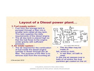
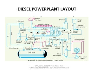
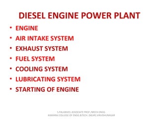
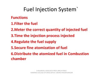
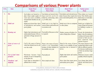
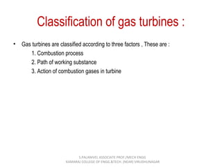
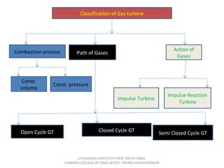
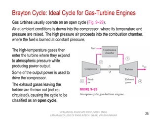
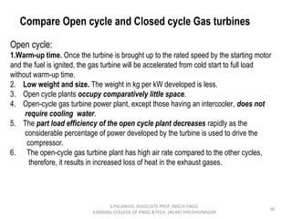
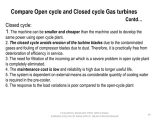
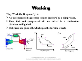

The document discusses diesel engine power plants and gas turbines, highlighting their applications, advantages, disadvantages, and operational principles. It details the structure and components of diesel engines and gas turbines, as well as the Brayton cycle and its efficiency factors. Additionally, comparisons between open and closed cycle gas turbines are made, noting the operational differences and maintenance implications.