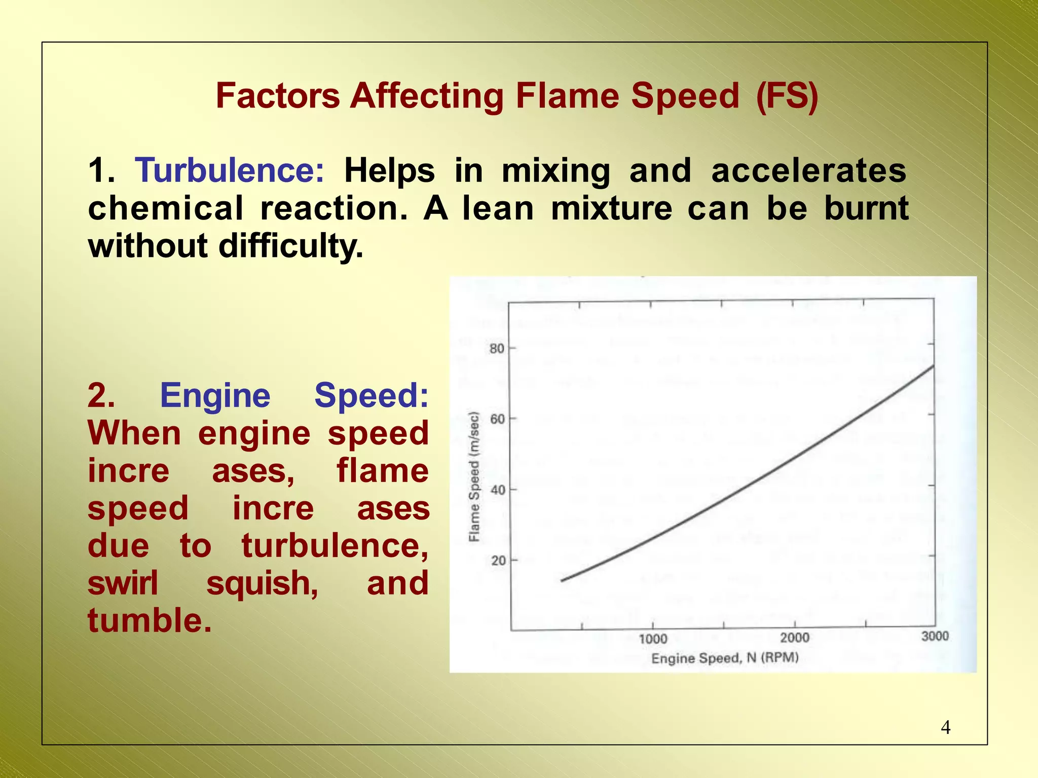
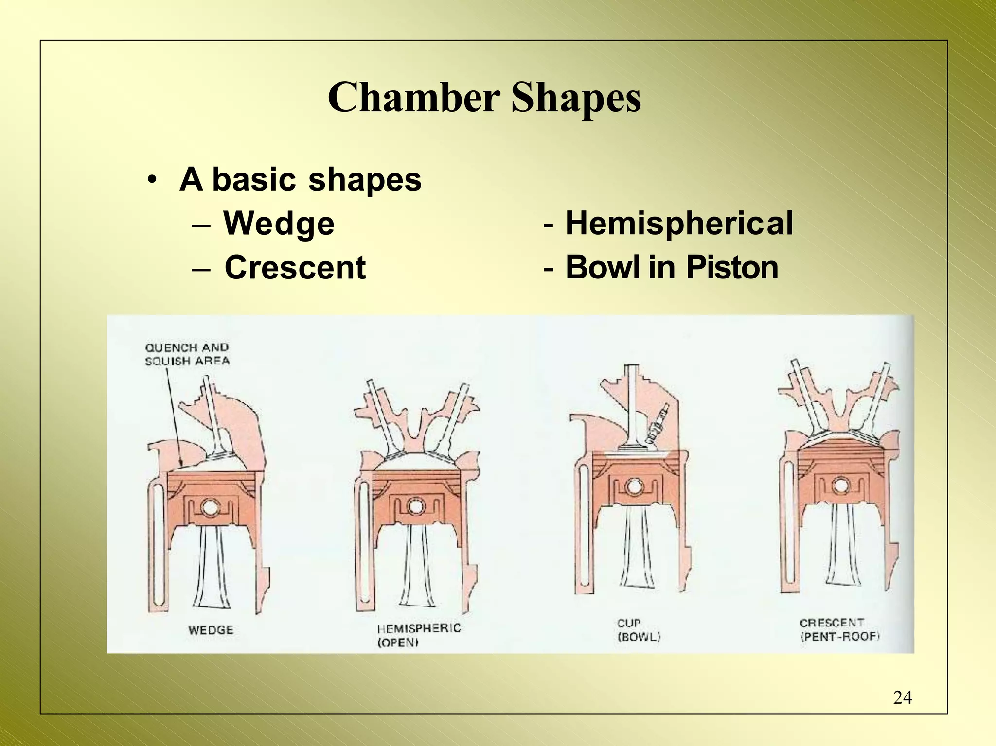
Internal Combustion Engines
Yashvir Singh, Ph.D.
1
Combustion in SI Engine
2
Normal Combustion: When the flame
travels evenly or uniformly across the
combustion chamber.
 Abnormal Combustion: When the
combustion gets deviated from the
normal behavior resulting in loss of
performance or damage to the engine.
Combustion is dependent upon the rate of
propagation of flame front (or flame speed).
Flame Front: Boundary or front surfa ce of the
flame that separates the burnt charges from
the unburnt one.
Flame Speed: The speed at which the flame
front travels.
Flame speed affects the combustion
phenomena, pressure developed
and power produced.
Burning rate of mixture depends on
the flame speed and shape / contour
of combustion chamber. 3
Factors Affecting Flame Speed (FS)
1. Turbulence: Helps in mixing and accelerates
chemical reaction. A lean mixture can be burnt
without difficulty.
2. Engine Speed:
When engine speed
incre ases, flame
speed incre ases
due to turbulence,
swirl squish, and
tumble.
4
Factors Affecting Flame Speed (FS)
5
3. Compression Ratio (CR): A higher CR
increases the pressure and temperature of
mixture. This reduces the initial phase of
combustion, and hence less ignition advance is
needed. High p and Tof the compressed mixture
speed up the 2nd phase of combustion.
Increased CR reduces the clearance volume,
and hence the density of charge. This further
incre ases the peak pressure and temperature,
reducing the total combustion duration. Thus, an
engine with higher CR have higher flame
speeds.
Factors Affecting Flame Speed (FS)
6
4. Inlet T
emp. & Pressure: FS increases with an
increase of inlet temperature and pressure. A
higher values of these
homogeneous mixture,
form a better
which helps in
increasing the FS.
5. Fuel-Air Ratio: The highest flame speeds
(minimum time for complete combustion) are
obtained with slightly rich mixture (point A).
When the mixture isleaner or richer, flame
speed decreases (a lean mixture releases less
thermal energy, and hence a lower flame
temperature; while a rich mixture leads to
incomplete combustion, and hence a release of less
thermal energy).
Effect of mixture strength on burning rate
7
8
Average flame speed in CC of an SI
engine as a function of air-fuel ratio.
Lean air-fuel mixtures have slower flame speeds
with maximum speed occurring when slightly rich
at an equivalence ratio near 1.2.
Stages of Combustion
a  b : Compression
b  c : Combustion
c  d : Expansion
Ideally, entire pressure rise during combustion occurs
at constant volume, i.e., when the piston isat TDC. 9
Actual p- diagram
I. Ignition lag (AB): Flame front begins to travel.
II. Spreading of Flame (BC): Flame spreads
throughout the Combustion Chamber.
III. Afterburning (CD): C isthe point of max. pressure,
a few degrees after TDC. Power stroke begins.
10
Effect of Ignition: Constant Volume Cycle
Because of ignition
lag, it is necessary to
ignite the charge in the
cylinder some degrees
before the crankshaft
reaches TDC. The
number of degrees
before TDC at which
ignition occurs is called
Ignition Advance.
The optimum angle of advance allows combustion
to cease just after TDC, so that maximum possible
pressure is built at a point just at the beginning of
expansion stroke. This is shown as the normal curve,
indic ating smooth engine running.
11
Effect of Over-advanced ignition
When the engine
ignition is over-advanced ,
combustion is initiated too
early and the cylinder
pressure begins to rise
rapidly while the piston is
still trying to complete its
compression stroke.
This creates excessive cylinder pressures and
may even produce shock waves in the cylinder as
illustrated by the ragged top on curve 2. An over-
advanced engine will run rough, it will tend to
overheat resulting in loss of power.
12
Effect of Retarded Ignition
 When the
13
engine ignition
is retarded (curve 3),
combustion is initiated late.
In fact, combustion will
continue while the piston is
out its power
sweeping
stroke.
Maximum pressure will occur late, and will not as
high as that of the normal case. A retarded engine
will produce less power output, and due to the late
burning the engine will run hot, and may cause
damage to the exhaust valves and ports.
Knocking
Flame travels from AD and compresses the end
charge BB´D and raises its temperature.
Temperature also increases due to heat transfer
from the flame front. Now, if the final temperature
is less than the auto-ignition temperature, Normal
Combustion occurs and charge BB´D is consumed
by the flame itself.
14
Knocking
15
Now, if the final temperature is greater than and
equal to the auto-ignition temperature, the
charge BB´D auto-ignites (knocking). A second
flame front develops and moves in opposite
direction, where the collision occurs between the
flames. This causes severe pressure pulsation,
and leads to engine damage/ failure.
Engine Damage From Severe Knock
Damage to the engine is caused by a combination
of high temperature and high pressure.
Piston Piston crown
Cylinder head gasket Aluminum cylinder head
16
Effect of Variables on Knock – Density Factors
Density Factors: Factors that reduce the
density of the charge also reduce the knocking
tendency by providing lower energy release.
1.Compression ratio (CR): When CR ratio
increases, p and T increase and an overall
incre ase in density of charge raises the
knocking tendency.
2.Mass of inducted charge: A reduction in
the mass of inducted charge (by throttling or
by reducing the amount of supercharging)
reduces both temperature and density at
the time of ignition. This decreases the
knocking tendency.
17
Effect of Variables on Knock – Density Factors
3.Inlet temperature of mixture: An incre ase in
the inlet temperature of mixture makes the
compression temperature higher. This incre ases
the knocking tendency. Further, volumetric
efficiency is lowered. Hence, a lower inlet
temperature is always preferred. However, it
should not be too low to cause starting and
vaporization problems.
4.Retarding spark timing: Having a spark closer
to TDC, peak pressures are reached down the
on the power stroke, and are of lower
magnitudes. This might reduce the knocking
tendency, however, it will affect the brake
torque and poweroutput.
18
Effect of Variables on Knock – Time Factors
Time Factors: Increasing the flame speed or the
ignition lag will tend to reduce the tendency to
knock.
1.Turbulence: Increase of turbulence
increases the flame speed and reduces the
time available for the end charge to reach
auto-ignition condition. This reduces the
knocking tendency.
2.Engine size: Flame requires more time to
travel in Combustion Chamber of larger
engines. Hence, a larger engines will have
more tendency to knock.
19
Effect of Variables on Knock – Time Factors
3.Engine speed: An incre ase in engine speed
incre ases the turbulence of the mixture
considerably resulting in incre ased flame
speed. Hence, knocking tendency reduces at
higher engine speeds.
4.Spark plug locations: To minimize the flame
travel distance, spark plug is located centrally.
For larger engines, two or more spark plugs are
located to achieve this.
20
Effect of Variables on Knock – Composition Factors
Composition Factors: These includes ratio of
air-fuel mixture, and the properties of fuel
employed in the engine.
1.Fuel-air ratio: The flame speeds are
affected by fuel-air ratio. Also, the flame
temperature and reaction time are different
for different fuel-air ratios.
2.Octane value: In general, paraffin series
of hydrocarbon have the maximum and
aromatic series the minimum tendency to
knock.
21
Combustion Chamber - Definition
• The combustion chamber consists of
an upper and lower half.
– Upper half- Made up of cylinder
head and cylinder wall.
– Lower half- Made up of piston
head (Crown) and piston rings.
22
Design Considerations
• Minimal flame travel
• The exhaust valve and spark plug
should be close together
• Sufficient turbulence
• A fast combustion, low variability
• High volumetric efficiency at WOT
• Minimum heat loss to combustion
walls
• Low fuel octane requirement
23
Chamber Shapes
• A basic shapes
– Wedge
– Crescent
- Hemispherical
- Bowl in Piston
24
Chamber Shapes
• Wedge
– Asymmetric design
– Valves at an angle
and off center
• Hemispherical (Hemi)
– Symmetric design
– Valves placed on
a arc shaped head
25
Chamber Shapes
• Bowl-in-Piston
– Symmetric design
– Valves are placed
perpendicular to head
• Crescent (Pent-Roof)
– The valves are placed
at an angle on flat
surfaces of the head
26
Fast Combustion
• Effect of spark plug location
Side plug w/o swirl
Side plug with
normal swirl
Side plug with
high swirl
Central plug w/o
swirl
Two plugs w/o swirl
27
28
Fast Combustion in Relation to Shape
Comparison of Burn Angles
29
Heat Transfer
• Want minimum heat transfer to
combustion chamber walls
• Open and hemispherical have
least heat transfer
• Bowl-in-piston has high heat
transfer
30
Low Octane
• Octane Requirement related to knock
• Close chambers (bowl-in-piston) have
higher knock at high compression
ratios than Open chambers
(hemispheric al and pent-roof)
31
32
Octane Rating
• Research Octane Number (RON)
• Motor Octane Number (MON)
• Octane is one factor in the combustion
process that another group will speak about
• Straight chain C-H bonds such as heptane
have weaker C-H bonds than branched
chained C-H bonds in branch chained HC
such as iso-octane
• Straight bonds are easier to break
Knock
• Surface ignition
– Caused by mixture igniting as a result of
contact with a hot surface, such as an
exhaust valve
• Self-Ignition
– Occurs when temperature and pressure
of unburned gas are high enough to
cause spontaneous ignition
33
Conclusion
• Optimum chamber
– Central spark plug location
– Minimum heat transfer
– Low octane requirement
– High turbulence
34

Combustion in si engine

  • 1.
  • 2.
    Combustion in SIEngine 2 Normal Combustion: When the flame travels evenly or uniformly across the combustion chamber.  Abnormal Combustion: When the combustion gets deviated from the normal behavior resulting in loss of performance or damage to the engine.
  • 3.
    Combustion is dependentupon the rate of propagation of flame front (or flame speed). Flame Front: Boundary or front surfa ce of the flame that separates the burnt charges from the unburnt one. Flame Speed: The speed at which the flame front travels. Flame speed affects the combustion phenomena, pressure developed and power produced. Burning rate of mixture depends on the flame speed and shape / contour of combustion chamber. 3
  • 4.
    Factors Affecting FlameSpeed (FS) 1. Turbulence: Helps in mixing and accelerates chemical reaction. A lean mixture can be burnt without difficulty. 2. Engine Speed: When engine speed incre ases, flame speed incre ases due to turbulence, swirl squish, and tumble. 4
  • 5.
    Factors Affecting FlameSpeed (FS) 5 3. Compression Ratio (CR): A higher CR increases the pressure and temperature of mixture. This reduces the initial phase of combustion, and hence less ignition advance is needed. High p and Tof the compressed mixture speed up the 2nd phase of combustion. Increased CR reduces the clearance volume, and hence the density of charge. This further incre ases the peak pressure and temperature, reducing the total combustion duration. Thus, an engine with higher CR have higher flame speeds.
  • 6.
    Factors Affecting FlameSpeed (FS) 6 4. Inlet T emp. & Pressure: FS increases with an increase of inlet temperature and pressure. A higher values of these homogeneous mixture, form a better which helps in increasing the FS. 5. Fuel-Air Ratio: The highest flame speeds (minimum time for complete combustion) are obtained with slightly rich mixture (point A). When the mixture isleaner or richer, flame speed decreases (a lean mixture releases less thermal energy, and hence a lower flame temperature; while a rich mixture leads to incomplete combustion, and hence a release of less thermal energy).
  • 7.
    Effect of mixturestrength on burning rate 7
  • 8.
    8 Average flame speedin CC of an SI engine as a function of air-fuel ratio. Lean air-fuel mixtures have slower flame speeds with maximum speed occurring when slightly rich at an equivalence ratio near 1.2.
  • 9.
    Stages of Combustion a b : Compression b  c : Combustion c  d : Expansion Ideally, entire pressure rise during combustion occurs at constant volume, i.e., when the piston isat TDC. 9
  • 10.
    Actual p- diagram I.Ignition lag (AB): Flame front begins to travel. II. Spreading of Flame (BC): Flame spreads throughout the Combustion Chamber. III. Afterburning (CD): C isthe point of max. pressure, a few degrees after TDC. Power stroke begins. 10
  • 11.
    Effect of Ignition:Constant Volume Cycle Because of ignition lag, it is necessary to ignite the charge in the cylinder some degrees before the crankshaft reaches TDC. The number of degrees before TDC at which ignition occurs is called Ignition Advance. The optimum angle of advance allows combustion to cease just after TDC, so that maximum possible pressure is built at a point just at the beginning of expansion stroke. This is shown as the normal curve, indic ating smooth engine running. 11
  • 12.
    Effect of Over-advancedignition When the engine ignition is over-advanced , combustion is initiated too early and the cylinder pressure begins to rise rapidly while the piston is still trying to complete its compression stroke. This creates excessive cylinder pressures and may even produce shock waves in the cylinder as illustrated by the ragged top on curve 2. An over- advanced engine will run rough, it will tend to overheat resulting in loss of power. 12
  • 13.
    Effect of RetardedIgnition  When the 13 engine ignition is retarded (curve 3), combustion is initiated late. In fact, combustion will continue while the piston is out its power sweeping stroke. Maximum pressure will occur late, and will not as high as that of the normal case. A retarded engine will produce less power output, and due to the late burning the engine will run hot, and may cause damage to the exhaust valves and ports.
  • 14.
    Knocking Flame travels fromAD and compresses the end charge BB´D and raises its temperature. Temperature also increases due to heat transfer from the flame front. Now, if the final temperature is less than the auto-ignition temperature, Normal Combustion occurs and charge BB´D is consumed by the flame itself. 14
  • 15.
    Knocking 15 Now, if thefinal temperature is greater than and equal to the auto-ignition temperature, the charge BB´D auto-ignites (knocking). A second flame front develops and moves in opposite direction, where the collision occurs between the flames. This causes severe pressure pulsation, and leads to engine damage/ failure.
  • 16.
    Engine Damage FromSevere Knock Damage to the engine is caused by a combination of high temperature and high pressure. Piston Piston crown Cylinder head gasket Aluminum cylinder head 16
  • 17.
    Effect of Variableson Knock – Density Factors Density Factors: Factors that reduce the density of the charge also reduce the knocking tendency by providing lower energy release. 1.Compression ratio (CR): When CR ratio increases, p and T increase and an overall incre ase in density of charge raises the knocking tendency. 2.Mass of inducted charge: A reduction in the mass of inducted charge (by throttling or by reducing the amount of supercharging) reduces both temperature and density at the time of ignition. This decreases the knocking tendency. 17
  • 18.
    Effect of Variableson Knock – Density Factors 3.Inlet temperature of mixture: An incre ase in the inlet temperature of mixture makes the compression temperature higher. This incre ases the knocking tendency. Further, volumetric efficiency is lowered. Hence, a lower inlet temperature is always preferred. However, it should not be too low to cause starting and vaporization problems. 4.Retarding spark timing: Having a spark closer to TDC, peak pressures are reached down the on the power stroke, and are of lower magnitudes. This might reduce the knocking tendency, however, it will affect the brake torque and poweroutput. 18
  • 19.
    Effect of Variableson Knock – Time Factors Time Factors: Increasing the flame speed or the ignition lag will tend to reduce the tendency to knock. 1.Turbulence: Increase of turbulence increases the flame speed and reduces the time available for the end charge to reach auto-ignition condition. This reduces the knocking tendency. 2.Engine size: Flame requires more time to travel in Combustion Chamber of larger engines. Hence, a larger engines will have more tendency to knock. 19
  • 20.
    Effect of Variableson Knock – Time Factors 3.Engine speed: An incre ase in engine speed incre ases the turbulence of the mixture considerably resulting in incre ased flame speed. Hence, knocking tendency reduces at higher engine speeds. 4.Spark plug locations: To minimize the flame travel distance, spark plug is located centrally. For larger engines, two or more spark plugs are located to achieve this. 20
  • 21.
    Effect of Variableson Knock – Composition Factors Composition Factors: These includes ratio of air-fuel mixture, and the properties of fuel employed in the engine. 1.Fuel-air ratio: The flame speeds are affected by fuel-air ratio. Also, the flame temperature and reaction time are different for different fuel-air ratios. 2.Octane value: In general, paraffin series of hydrocarbon have the maximum and aromatic series the minimum tendency to knock. 21
  • 22.
    Combustion Chamber -Definition • The combustion chamber consists of an upper and lower half. – Upper half- Made up of cylinder head and cylinder wall. – Lower half- Made up of piston head (Crown) and piston rings. 22
  • 23.
    Design Considerations • Minimalflame travel • The exhaust valve and spark plug should be close together • Sufficient turbulence • A fast combustion, low variability • High volumetric efficiency at WOT • Minimum heat loss to combustion walls • Low fuel octane requirement 23
  • 24.
    Chamber Shapes • Abasic shapes – Wedge – Crescent - Hemispherical - Bowl in Piston 24
  • 25.
    Chamber Shapes • Wedge –Asymmetric design – Valves at an angle and off center • Hemispherical (Hemi) – Symmetric design – Valves placed on a arc shaped head 25
  • 26.
    Chamber Shapes • Bowl-in-Piston –Symmetric design – Valves are placed perpendicular to head • Crescent (Pent-Roof) – The valves are placed at an angle on flat surfaces of the head 26
  • 27.
    Fast Combustion • Effectof spark plug location Side plug w/o swirl Side plug with normal swirl Side plug with high swirl Central plug w/o swirl Two plugs w/o swirl 27
  • 28.
    28 Fast Combustion inRelation to Shape
  • 29.
  • 30.
    Heat Transfer • Wantminimum heat transfer to combustion chamber walls • Open and hemispherical have least heat transfer • Bowl-in-piston has high heat transfer 30
  • 31.
    Low Octane • OctaneRequirement related to knock • Close chambers (bowl-in-piston) have higher knock at high compression ratios than Open chambers (hemispheric al and pent-roof) 31
  • 32.
    32 Octane Rating • ResearchOctane Number (RON) • Motor Octane Number (MON) • Octane is one factor in the combustion process that another group will speak about • Straight chain C-H bonds such as heptane have weaker C-H bonds than branched chained C-H bonds in branch chained HC such as iso-octane • Straight bonds are easier to break
  • 33.
    Knock • Surface ignition –Caused by mixture igniting as a result of contact with a hot surface, such as an exhaust valve • Self-Ignition – Occurs when temperature and pressure of unburned gas are high enough to cause spontaneous ignition 33
  • 34.
    Conclusion • Optimum chamber –Central spark plug location – Minimum heat transfer – Low octane requirement – High turbulence 34