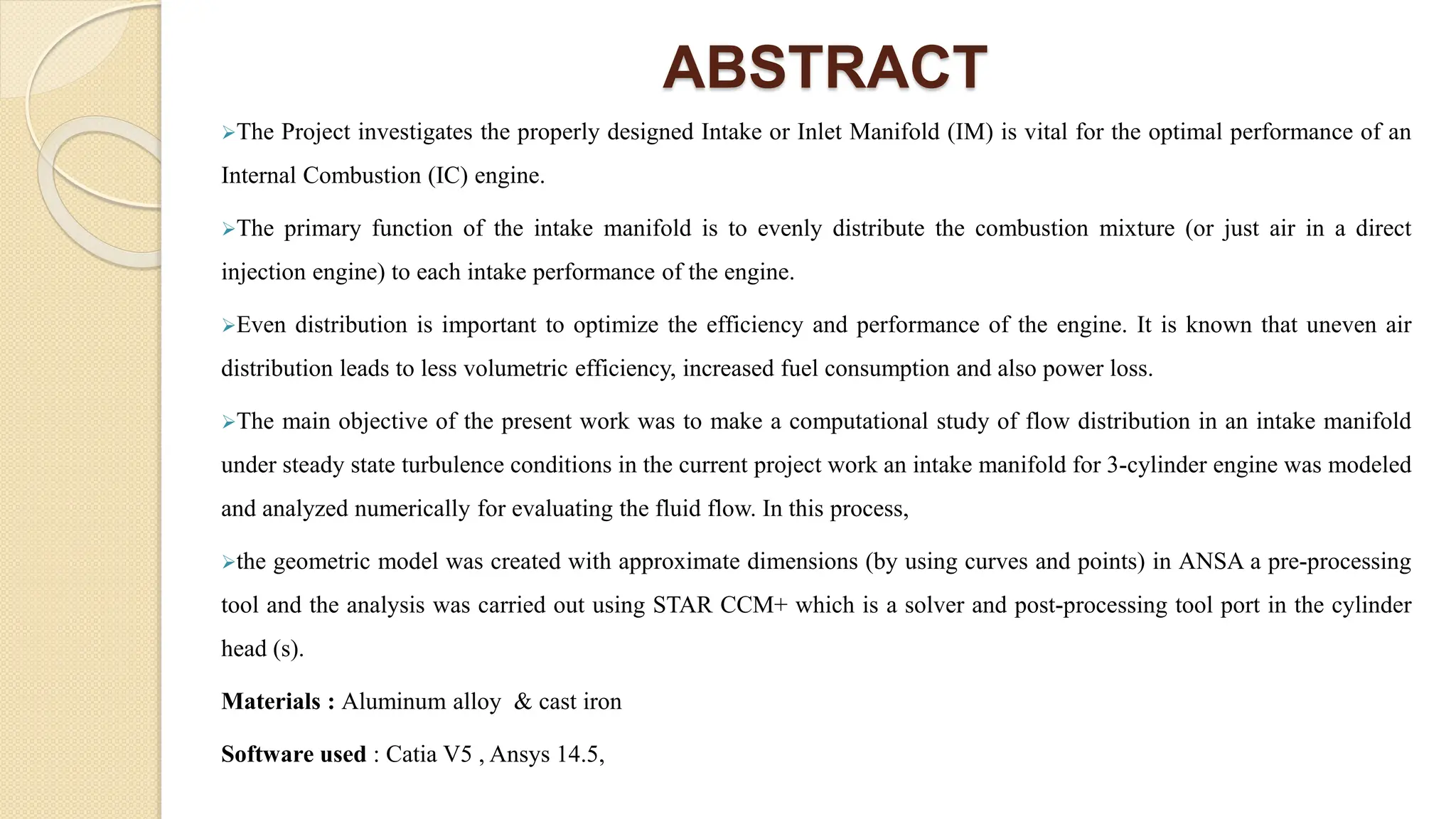
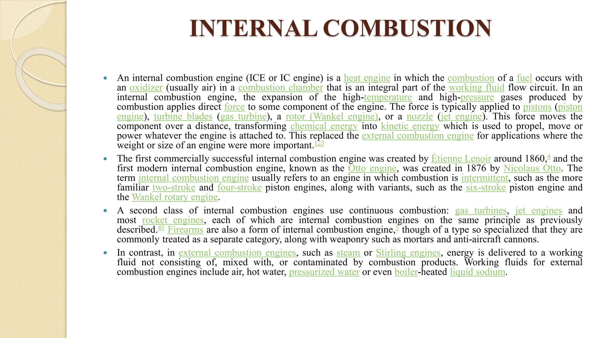
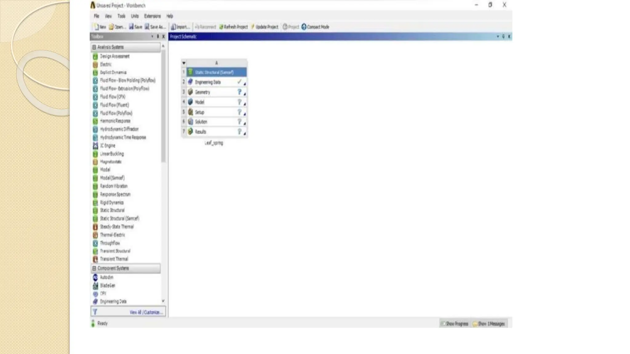
DESIGN AND ANALYSIS OF INTAKE
MANIFOLD OF IC ENGINE WITH
VARIOUS MATERIALS
ABSTRACT
The Project investigates the properly designed Intake or Inlet Manifold (IM) is vital for the optimal performance of an
Internal Combustion (IC) engine.
The primary function of the intake manifold is to evenly distribute the combustion mixture (or just air in a direct
injection engine) to each intake performance of the engine.
Even distribution is important to optimize the efficiency and performance of the engine. It is known that uneven air
distribution leads to less volumetric efficiency, increased fuel consumption and also power loss.
The main objective of the present work was to make a computational study of flow distribution in an intake manifold
under steady state turbulence conditions in the current project work an intake manifold for 3-cylinder engine was modeled
and analyzed numerically for evaluating the fluid flow. In this process,
the geometric model was created with approximate dimensions (by using curves and points) in ANSA a pre-processing
tool and the analysis was carried out using STAR CCM+ which is a solver and post-processing tool port in the cylinder
head (s).
Materials : Aluminum alloy & cast iron
Software used : Catia V5 , Ansys 14.5,
DESIGN OF PROJECT
Materials :
 Aluminum alloy & cast iron
Software used :
• Catia V5 Ansys 14.5
selection ports
Intake manifold of ic engine
INTRODUCTION
An inlet manifold or intake manifold (in American English) is the a part of an engine that components the
gas/air aggregate to the cylinders. The word manifold comes from the Old English phrase manigfeald
(from the Anglo-Saxon manig many and feald repeatedly) and refers to the multiplying of one (pipe) into
many.
In contrast, an exhaust manifold collects the exhaust gases from more than one cylinders right into a
smaller range of pipes – regularly down to one pipe. The number one characteristic of the consumption
manifold is to frivolously distribute the combustion aggregate (or simply air in an instantaneous injection
engine) to each intake port in the cylinder head(s).
performance and performance of the engine. It might also function a mount for the carburetor, throttle
frame, gasoline injectors and other components of the engine. Due to the downward movement of the
pistons and the restrict resulting from the throttle valve, in a reciprocating spark ignition piston engine, a
partial vacuum (decrease than atmospheric stress) exists within the intake manifold. This manifold vacuum
can be extensive, and can be used as a supply of vehicle ancillary electricity to drive auxiliary systems:
energy assisted brakes, emission control gadgets, cruise manipulate, ignition boost, windshield wipers,
power home windows, air flow gadget valves, etc.
This vacuum also can be used to attract any piston blow-by means of gases from the engine's crankcase.
This is called a high-quality crankcase ventilation device, wherein the gases are burned with the gas/air
mixture. The intake manifold has traditionally been fabricated from aluminum or cast iron, but use of
composite plastic substances is gaining recognition.
 Modern intake manifolds usually employ runners, individual tubes extending to each
intake port on the cylinder head which emanate from a central volume or "plenum"
beneath the carburetor. The purpose of the runner is to take advantage of the Helmholtz
resonance property of air.
 Air flows at considerable speed through the open valve. When the valve closes, the air
that has not yet entered the valve still has a lot of momentum and compresses against the
valve, creating a pocket of high pressure. This high-pressure air begins to equalize with
lower-pressure air in the manifold.
 Due to the air's inertia, the equalization will tend to oscillate: At first the air in the runner
will be at a lower pressure than the manifold. The air in the manifold then tries to equalize
back into the runner, and the oscillation repeats. This process occurs at the speed of sound,
and in most manifolds travels up and down the runner many times before the valve opens
again.
 The smaller the cross-sectional area of the runner, the higher the pressure changes on
resonance for a given airflow. This aspect of Helmholtz resonance reproduces one result
of the Venturi effect. When the piston accelerates downwards, the pressure at the output of
the intake runner is reduced. This low pressure pulse runs to the input end, where it is
converted into an over-pressure pulse. This pulse travels back through the runner and
rams air through the valve. The valve then closes.
INTERNAL COMBUSTION
 An internal combustion engine (ICE or IC engine) is a heat engine in which the combustion of a fuel occurs with
an oxidizer (usually air) in a combustion chamber that is an integral part of the working fluid flow circuit. In an
internal combustion engine, the expansion of the high-temperature and high-pressure gases produced by
combustion applies direct force to some component of the engine. The force is typically applied to pistons (piston
engine), turbine blades (gas turbine), a rotor (Wankel engine), or a nozzle (jet engine). This force moves the
component over a distance, transforming chemical energy into kinetic energy which is used to propel, move or
power whatever the engine is attached to. This replaced the external combustion engine for applications where the
weight or size of an engine were more important.123
 The first commercially successful internal combustion engine was created by Étienne Lenoir around 1860,4 and the
first modern internal combustion engine, known as the Otto engine, was created in 1876 by Nicolaus Otto. The
term internal combustion engine usually refers to an engine in which combustion is intermittent, such as the more
familiar two-stroke and four-stroke piston engines, along with variants, such as the six-stroke piston engine and
the Wankel rotary engine.
 A second class of internal combustion engines use continuous combustion: gas turbines, jet engines and
most rocket engines, each of which are internal combustion engines on the same principle as previously
described.45 Firearms are also a form of internal combustion engine,5 though of a type so specialized that they are
commonly treated as a separate category, along with weaponry such as mortars and anti-aircraft cannons.
 In contrast, in external combustion engines, such as steam or Stirling engines, energy is delivered to a working
fluid not consisting of, mixed with, or contaminated by combustion products. Working fluids for external
combustion engines include air, hot water, pressurized water or even boiler-heated liquid sodium.
The base of a reciprocating internal combustion engine is the engine block, which is
typically made of cast iron (due to its good wear resistance and low cost)or aluminum. In the
latter case, the cylinder liners are made of cast iron or steel,or a coating such as nikasil or alusil.
The engine block contains the cylinders.
In engines with more than one cylinder they are usually arranged either in 1 row
(straight engine) or 2 rows (boxer engine or V engine); 3 rows are occasionally used (W engine)
in contemporary engines, and other engine configurations are possible and have been used.
Single cylinder engines (or thumpers) are common for motorcycles and other small engines
found in light machinery. On the outer side of the cylinder, passages that contain cooling fluid
are cast into the engine block whereas, in some heavy duty engines, the passages are the types of
removable cylinder sleeves which can be replaceable.
Water-cooled engines contain passages in the engine block where cooling fluid
circulates (the water jacket). Some small engines are air-cooled, and instead of having a water
jacket the cylinder block has fins protruding away from it to cool the engine by directly
transferring heat to the air.
The cylinder walls are usually finished by honing to obtain a cross hatch, which is able
to retain more oil. A too rough surface would quickly harm the engine by excessive wear on the
piston.
SCOPE
The breathing capacity of the intake manifold should maximum for
higher volumetric efficiency. The main aim or objective of any
manufacturer is to create an efficient model by varying the Materials.
Intake manifold is the breathing system of any engine. Design of intake
manifold for light duty locomotive engine by adopting different
approaches and various analytical calculations also analyze fluid flow
characteristics of intake manifold by using CAE and CFD. Recent
development in the computer simulation-based methods for designing
automotive components had been gaining popularity even though the
results obtained from numerical simulation (CFD) were comparable
with the experimental studies; there’s been continuous research to
improve the simulation accuracy.
STEPS IN METHODOLOGY
 1. Analytical calculations for different materials used for
manifo;d
 2. Generating the model using CAD software
 3. CAE Analysis for determination of vibrations and
localization of thermal stresses
 4. Perform CFD analysis to study the flow of mixture and
its through intake manifold
 5. Verification and comparison of results
 6. Optimization and reconstructing the model
LITERATURE SURVEY
 1 Ryan I., Christopher B. W., “Design and Manufacture of a Formula SAE Intake System
Using Fused Deposition Modeling and FiberReinforced Composite Rapid Prototyping”,
Journal, Vol. 16 Is: 3, pp.174 – 179.
 2 Heavy Duty Engines – MTZ 6/2005. 4. Jacobs, T., Chatterjee, S., Conway, R., Walker, A.,
Kramer, J. and K. Mueller-Haas, Development of a PartialFilter Technology for Hdd
Retrofit, Sae Technical Paper 2006-01-0213. 56 K. S. Umesh, V. K. Pravin& K. Rajagopal
 Shrinath Potul, Rohan Nachnolkar, Sagar Bhave
 described in Analysis of Change In Intake Manifold Length And Development Of Variable
Intake System that Gas dynamics of intake system plays a key role in deciding the
performance of an engine. This dynamic is different for fuel injected and carbureted engine
and vary according to type of engine, number of cylinders, temperature at inlet, valve timing,
valve angle and other factors. Careful design of the manifolds enables the engineer
(designer) to manipulate the characteristics to the desired level. This paper investigates the
effects of intake runner length on the performance characteristics of a four-stroke, single
cylinder spark-ignited engine with electronically controlled fuel injector. In this paper basic
intake tuning mechanisms were described. Engine performance characteristics such as brake
torque, brake power, brake mean effective pressure and specific fuel consumption were
taken into consideration and virtual simulation software
ALUMINIUM ALLOY
 An aluminium alloy (or aluminum alloy; see spelling differences) is an alloy in
which aluminium (Al) is the predominant metal. The typical alloying elements
are copper, magnesium, manganese, silicon, tin, nickel and zinc. There are two
principal classifications, namely casting alloys and wrought alloys, both of which
are further subdivided into the categories heat-treatable and non-heat-treatable.
About 85% of aluminium is used for wrought products, for example rolled plate,
foils and extrusions. Cast aluminium alloys yield cost-effective products due to the
low melting point, although they generally have lower tensile strengths than
wrought alloys. The most important cast aluminium alloy system is Al–Si, where
the high levels of silicon (4–13%) contribute to give good casting characteristics.
Aluminium alloys are widely used in engineering structures and components where
light weight or corrosion resistance is required.1
 Alloys composed mostly of aluminium have been very important in aerospace
manufacturing since the introduction of metal-skinned aircraft. Aluminium–
magnesium alloys are both lighter than other aluminium alloys and much less
flammable than other alloys that contain a very high percentage of magnesium.2
CAST IRON

 Cast iron is a class of iron–carbon alloys with a carbon content more than 2%.1 Its usefulness derives
from its relatively low melting temperature. The alloy constituents affect its color when fractured;
white cast iron has carbide impurities which allow cracks to pass straight through, grey cast iron has
graphite flakes which deflect a passing crack and initiate countless new cracks as the material breaks,
and ductile cast iron has spherical graphite "nodules" which stop the crack from further progressing.
 Carbon (C), ranging from 1.8 to 4 wt%, and silicon (Si), 1–3 wt%, are the main alloying elements of
cast iron. Iron alloys with lower carbon content are known as steel.
 Cast iron tends to be brittle, except for malleable cast irons. With its relatively low melting point, good
fluidity, castability, excellent machinability, resistance to deformation and wear resistance, cast irons
have become an engineering material with a wide range of applications and are used in pipes,
machines and automotive industry parts, such as cylinder heads, cylinder blocks and gearbox cases. It
is resistant to damage by oxidation but is notoriously difficult to weld.
 The earliest cast-iron artefacts date to the 5th century BC, and were discovered by archaeologists in
what is now Jiangsu, China. Cast iron was used in ancient China for warfare, agriculture, and
architecture.2 During the 15th century AD, cast iron became utilized for cannon in Burgundy, France,
and in England during the Reformation. The amounts of cast iron used for cannons required large-scale
production.3 The first cast-iron bridge was built during the 1770s by Abraham Darby III, and is known
as the Iron Bridge in Shropshire, England. Cast iron was also used in the construction of buildings.
CARBON FIBERS
 Carbon fibers or carbon fibres (alternatively CF, graphite fiber or graphite fibre) are fibers about 5 to
10 micrometers (0.00020–0.00039 in) in diameter and composed mostly of carbon atoms.1 Carbon
fibers have several advantages: high stiffness, high tensile strength, high strength to weight ratio, high
chemical resistance, high-temperature tolerance, and low thermal expansion.2 These properties have
made carbon fiber very popular in aerospace, civil engineering, military, motorsports, and other
competition sports.3 However, they are relatively expensive compared to similar fibers, such as glass
fiber, basalt fibers, or plastic fibers.4
 To produce a carbon fiber, the carbon atoms are bonded together in crystals that are more or less
aligned parallel to the fiber's long axis as the crystal alignment gives the fiber a high strength-to-
volume ratio (in other words, it is strong for its size). Several thousand carbon fibers are bundled
together to form a tow, which may be used by itself or woven into a fabric.
 Carbon fibers are usually combined with other materials to form a composite. For example, when
permeated with a plastic resin and baked, it forms carbon-fiber-reinforced polymer (often referred to as
carbon fiber), which has a very high strength-to-weight ratio and is extremely rigid although somewhat
brittle. Carbon fibers are also composited with other materials, such as graphite, to form reinforced
carbon-carbon composites, which have a very high heat tolerance. Carbon fiber-reinforced composite
materials are used to make aircraft and spacecraft parts, racing car bodies, golf club shafts, bicycle
frames, fishing rods, automobile springs, sailboat masts, and many other components where light
weight and high strength are needed.
SOFTWARES
CATIA
 CATIA (/kəˈtiːə/, an acronym of computer-aided three-dimensional interactive application)
is a multi-platform software suite for computer-aided design (CAD), computer-aided
manufacturing (CAM), computer-aided engineering (CAE), 3D modeling and product
lifecycle management (PLM), developed by the French company Dassault SystèmesSince it
supports multiple stages of product development from conceptualization, design and
engineering to manufacturing, it is considered a CAx-software and is sometimes referred to
as a 3D Product Lifecycle Management software suite. Like most of its competition it
facilitates collaborative engineering through an integrated cloud service and have support to
be used across disciplines including surfacing & shape design, electrical, fluid and electronic
systems design, mechanical engineering and systems engineering.
 Besides being used in a wide range of industries from aerospace and defence to packaging
design, CATIA has been used by architect Frank Gehry to design some of his
signature curvilinear buildings2 and his company Gehry Technologies was developing
their Digital Project software based on CATIA.3
 The software has been merged with the company's other software suite 3D XML Player to
form the combined Solidworks Composer Player.
ANSYS
 Ansys was founded in 1970 by John Swanson, who sold his interest in the company to
venture capitalists in 1993. Ansys went public on NASDAQ in 1996. In the 2000s, the
company acquired other engineering design companies, obtaining additional technology for
fluid dynamics, electronics design, and physics analysis. Ansys became a component of the
NASDAQ-100 index on December 23, 2019.2
 The idea for Ansys was first conceived by John Swanson while working at the Westinghouse
Astronuclear Laboratory in the 1960s.3 At the time, engineers performed finite element
analysis (FEA) by hand.3 Westinghouse rejected Swanson's idea to automate FEA by
developing general purpose engineering software, so Swanson left the company in 1969 to
develop the software on his own.3 He founded Ansys under the name
Swanson Analysis Systems Inc. (SASI) the next year, working out of his farmhouse
in Pittsburgh.45
 Swanson developed the initial Ansys software on punch-cards and used a mainframe
computer that was rented by the hour.3 Westinghouse hired Swanson as a consultant, under
the condition that any code he developed for Westinghouse could also be included in the
Ansys product line.4 Westinghouse also became the first Ansys user.
WORK STATUS
Work Done
 Research about ic engine & inlet manifold From previous journal’s.
 Choosed materials for compared with exiting materials
 Installed required software like Catia v5 & Ansys
Work on Process
 Making Model on Catia v5
 After that we do simulation for comparisons various results from various
materials on Ansys.
CONCLUSIONS
Based on this extensive research work, the following were the conclusion. A new
analysis simulation methodology in terms of boundary conditions – For the intake
manifold was proposed. The result from this approach was in close agreement with
experimental data. High flow swirl had been noted for all the operating conditions
which could enhance the engine combustion characteristics. It can be easily
concluded that intake geometry made a conside5rable impact of outlet velocity. The
main impact is on the volumetric efficiency of the engine which ultimately affects
the torque and power produced a different engine speed. The intake manifold
design with less curvature at the runner. This is shown in results there is a
percentage increase in outlet velocity as compared to conventional manifold model
of INDICA VISTA. Based on the computational fluid dynamics theory, three
dimensional numerical simulation of the engine’s intake manifold system is carried
out, which is an effective and feasible method of analysis. The results shows that
the pressure loss and flow uniformity of intake manifold are two major evolution
indicators.
REFERENCES
 1) Shrinath Potul, Rohan Nachnolkar, Sagar Bhave, “Analysis of Change in
Intake Manifold Length and Development of Variable Intake System”.
‘INTERNATIONAL JOURNAL OF SCIENTIFIC & TECHNOLOGY
RESEARCH’ VOLUME 3, ISSUE 5, MAY 2014 ISSN 2277-8616
 2) M. A. A. H. Pahmi, Sharzali Che Mat, A. N. Nasruddin,Mohd Fauzi Ismail,
Mohd Najib Yusof, “The Analysis of Intake Manifold Air Stream Velocity on
Different Material Roughness” ISSN: 1662-7482, Vol. 661, pp 143-
147[2014-06-20]
 3) A. Jason D’Mello, B. Omkar S. Siras, “Performance Analysis for 4-
Cylinder Intake Manifold”, ‘An Experimental and Numerical Approach.
International Engineering Research Journal’ Page No 917-922 [2014]
 4) Arvindkumar Ka ; Adhithiyan Nb ;Darsak V Sc; Dinesh Cd “Optimisation
of Intake Manifold Design Using Fibre Reinforced Plastic”, ‘International
Journal of Scientific & Engineering Research’, Volume 5, Issue 4, April-2014
ISSN 2229-5518, 922

phase 1 Design and analysis of intake manifold of ic engine with various materials.pptx

  • 1.
    DESIGN AND ANALYSISOF INTAKE MANIFOLD OF IC ENGINE WITH VARIOUS MATERIALS
  • 2.
    ABSTRACT The Project investigatesthe properly designed Intake or Inlet Manifold (IM) is vital for the optimal performance of an Internal Combustion (IC) engine. The primary function of the intake manifold is to evenly distribute the combustion mixture (or just air in a direct injection engine) to each intake performance of the engine. Even distribution is important to optimize the efficiency and performance of the engine. It is known that uneven air distribution leads to less volumetric efficiency, increased fuel consumption and also power loss. The main objective of the present work was to make a computational study of flow distribution in an intake manifold under steady state turbulence conditions in the current project work an intake manifold for 3-cylinder engine was modeled and analyzed numerically for evaluating the fluid flow. In this process, the geometric model was created with approximate dimensions (by using curves and points) in ANSA a pre-processing tool and the analysis was carried out using STAR CCM+ which is a solver and post-processing tool port in the cylinder head (s). Materials : Aluminum alloy & cast iron Software used : Catia V5 , Ansys 14.5,
  • 3.
    DESIGN OF PROJECT Materials:  Aluminum alloy & cast iron Software used : • Catia V5 Ansys 14.5 selection ports Intake manifold of ic engine
  • 4.
    INTRODUCTION An inlet manifoldor intake manifold (in American English) is the a part of an engine that components the gas/air aggregate to the cylinders. The word manifold comes from the Old English phrase manigfeald (from the Anglo-Saxon manig many and feald repeatedly) and refers to the multiplying of one (pipe) into many. In contrast, an exhaust manifold collects the exhaust gases from more than one cylinders right into a smaller range of pipes – regularly down to one pipe. The number one characteristic of the consumption manifold is to frivolously distribute the combustion aggregate (or simply air in an instantaneous injection engine) to each intake port in the cylinder head(s). performance and performance of the engine. It might also function a mount for the carburetor, throttle frame, gasoline injectors and other components of the engine. Due to the downward movement of the pistons and the restrict resulting from the throttle valve, in a reciprocating spark ignition piston engine, a partial vacuum (decrease than atmospheric stress) exists within the intake manifold. This manifold vacuum can be extensive, and can be used as a supply of vehicle ancillary electricity to drive auxiliary systems: energy assisted brakes, emission control gadgets, cruise manipulate, ignition boost, windshield wipers, power home windows, air flow gadget valves, etc. This vacuum also can be used to attract any piston blow-by means of gases from the engine's crankcase. This is called a high-quality crankcase ventilation device, wherein the gases are burned with the gas/air mixture. The intake manifold has traditionally been fabricated from aluminum or cast iron, but use of composite plastic substances is gaining recognition.
  • 6.
     Modern intakemanifolds usually employ runners, individual tubes extending to each intake port on the cylinder head which emanate from a central volume or "plenum" beneath the carburetor. The purpose of the runner is to take advantage of the Helmholtz resonance property of air.  Air flows at considerable speed through the open valve. When the valve closes, the air that has not yet entered the valve still has a lot of momentum and compresses against the valve, creating a pocket of high pressure. This high-pressure air begins to equalize with lower-pressure air in the manifold.  Due to the air's inertia, the equalization will tend to oscillate: At first the air in the runner will be at a lower pressure than the manifold. The air in the manifold then tries to equalize back into the runner, and the oscillation repeats. This process occurs at the speed of sound, and in most manifolds travels up and down the runner many times before the valve opens again.  The smaller the cross-sectional area of the runner, the higher the pressure changes on resonance for a given airflow. This aspect of Helmholtz resonance reproduces one result of the Venturi effect. When the piston accelerates downwards, the pressure at the output of the intake runner is reduced. This low pressure pulse runs to the input end, where it is converted into an over-pressure pulse. This pulse travels back through the runner and rams air through the valve. The valve then closes.
  • 8.
    INTERNAL COMBUSTION  Aninternal combustion engine (ICE or IC engine) is a heat engine in which the combustion of a fuel occurs with an oxidizer (usually air) in a combustion chamber that is an integral part of the working fluid flow circuit. In an internal combustion engine, the expansion of the high-temperature and high-pressure gases produced by combustion applies direct force to some component of the engine. The force is typically applied to pistons (piston engine), turbine blades (gas turbine), a rotor (Wankel engine), or a nozzle (jet engine). This force moves the component over a distance, transforming chemical energy into kinetic energy which is used to propel, move or power whatever the engine is attached to. This replaced the external combustion engine for applications where the weight or size of an engine were more important.123  The first commercially successful internal combustion engine was created by Étienne Lenoir around 1860,4 and the first modern internal combustion engine, known as the Otto engine, was created in 1876 by Nicolaus Otto. The term internal combustion engine usually refers to an engine in which combustion is intermittent, such as the more familiar two-stroke and four-stroke piston engines, along with variants, such as the six-stroke piston engine and the Wankel rotary engine.  A second class of internal combustion engines use continuous combustion: gas turbines, jet engines and most rocket engines, each of which are internal combustion engines on the same principle as previously described.45 Firearms are also a form of internal combustion engine,5 though of a type so specialized that they are commonly treated as a separate category, along with weaponry such as mortars and anti-aircraft cannons.  In contrast, in external combustion engines, such as steam or Stirling engines, energy is delivered to a working fluid not consisting of, mixed with, or contaminated by combustion products. Working fluids for external combustion engines include air, hot water, pressurized water or even boiler-heated liquid sodium.
  • 9.
    The base ofa reciprocating internal combustion engine is the engine block, which is typically made of cast iron (due to its good wear resistance and low cost)or aluminum. In the latter case, the cylinder liners are made of cast iron or steel,or a coating such as nikasil or alusil. The engine block contains the cylinders. In engines with more than one cylinder they are usually arranged either in 1 row (straight engine) or 2 rows (boxer engine or V engine); 3 rows are occasionally used (W engine) in contemporary engines, and other engine configurations are possible and have been used. Single cylinder engines (or thumpers) are common for motorcycles and other small engines found in light machinery. On the outer side of the cylinder, passages that contain cooling fluid are cast into the engine block whereas, in some heavy duty engines, the passages are the types of removable cylinder sleeves which can be replaceable. Water-cooled engines contain passages in the engine block where cooling fluid circulates (the water jacket). Some small engines are air-cooled, and instead of having a water jacket the cylinder block has fins protruding away from it to cool the engine by directly transferring heat to the air. The cylinder walls are usually finished by honing to obtain a cross hatch, which is able to retain more oil. A too rough surface would quickly harm the engine by excessive wear on the piston.
  • 11.
    SCOPE The breathing capacityof the intake manifold should maximum for higher volumetric efficiency. The main aim or objective of any manufacturer is to create an efficient model by varying the Materials. Intake manifold is the breathing system of any engine. Design of intake manifold for light duty locomotive engine by adopting different approaches and various analytical calculations also analyze fluid flow characteristics of intake manifold by using CAE and CFD. Recent development in the computer simulation-based methods for designing automotive components had been gaining popularity even though the results obtained from numerical simulation (CFD) were comparable with the experimental studies; there’s been continuous research to improve the simulation accuracy.
  • 12.
    STEPS IN METHODOLOGY 1. Analytical calculations for different materials used for manifo;d  2. Generating the model using CAD software  3. CAE Analysis for determination of vibrations and localization of thermal stresses  4. Perform CFD analysis to study the flow of mixture and its through intake manifold  5. Verification and comparison of results  6. Optimization and reconstructing the model
  • 13.
    LITERATURE SURVEY  1Ryan I., Christopher B. W., “Design and Manufacture of a Formula SAE Intake System Using Fused Deposition Modeling and FiberReinforced Composite Rapid Prototyping”, Journal, Vol. 16 Is: 3, pp.174 – 179.  2 Heavy Duty Engines – MTZ 6/2005. 4. Jacobs, T., Chatterjee, S., Conway, R., Walker, A., Kramer, J. and K. Mueller-Haas, Development of a PartialFilter Technology for Hdd Retrofit, Sae Technical Paper 2006-01-0213. 56 K. S. Umesh, V. K. Pravin& K. Rajagopal  Shrinath Potul, Rohan Nachnolkar, Sagar Bhave  described in Analysis of Change In Intake Manifold Length And Development Of Variable Intake System that Gas dynamics of intake system plays a key role in deciding the performance of an engine. This dynamic is different for fuel injected and carbureted engine and vary according to type of engine, number of cylinders, temperature at inlet, valve timing, valve angle and other factors. Careful design of the manifolds enables the engineer (designer) to manipulate the characteristics to the desired level. This paper investigates the effects of intake runner length on the performance characteristics of a four-stroke, single cylinder spark-ignited engine with electronically controlled fuel injector. In this paper basic intake tuning mechanisms were described. Engine performance characteristics such as brake torque, brake power, brake mean effective pressure and specific fuel consumption were taken into consideration and virtual simulation software
  • 14.
    ALUMINIUM ALLOY  Analuminium alloy (or aluminum alloy; see spelling differences) is an alloy in which aluminium (Al) is the predominant metal. The typical alloying elements are copper, magnesium, manganese, silicon, tin, nickel and zinc. There are two principal classifications, namely casting alloys and wrought alloys, both of which are further subdivided into the categories heat-treatable and non-heat-treatable. About 85% of aluminium is used for wrought products, for example rolled plate, foils and extrusions. Cast aluminium alloys yield cost-effective products due to the low melting point, although they generally have lower tensile strengths than wrought alloys. The most important cast aluminium alloy system is Al–Si, where the high levels of silicon (4–13%) contribute to give good casting characteristics. Aluminium alloys are widely used in engineering structures and components where light weight or corrosion resistance is required.1  Alloys composed mostly of aluminium have been very important in aerospace manufacturing since the introduction of metal-skinned aircraft. Aluminium– magnesium alloys are both lighter than other aluminium alloys and much less flammable than other alloys that contain a very high percentage of magnesium.2
  • 15.
    CAST IRON   Castiron is a class of iron–carbon alloys with a carbon content more than 2%.1 Its usefulness derives from its relatively low melting temperature. The alloy constituents affect its color when fractured; white cast iron has carbide impurities which allow cracks to pass straight through, grey cast iron has graphite flakes which deflect a passing crack and initiate countless new cracks as the material breaks, and ductile cast iron has spherical graphite "nodules" which stop the crack from further progressing.  Carbon (C), ranging from 1.8 to 4 wt%, and silicon (Si), 1–3 wt%, are the main alloying elements of cast iron. Iron alloys with lower carbon content are known as steel.  Cast iron tends to be brittle, except for malleable cast irons. With its relatively low melting point, good fluidity, castability, excellent machinability, resistance to deformation and wear resistance, cast irons have become an engineering material with a wide range of applications and are used in pipes, machines and automotive industry parts, such as cylinder heads, cylinder blocks and gearbox cases. It is resistant to damage by oxidation but is notoriously difficult to weld.  The earliest cast-iron artefacts date to the 5th century BC, and were discovered by archaeologists in what is now Jiangsu, China. Cast iron was used in ancient China for warfare, agriculture, and architecture.2 During the 15th century AD, cast iron became utilized for cannon in Burgundy, France, and in England during the Reformation. The amounts of cast iron used for cannons required large-scale production.3 The first cast-iron bridge was built during the 1770s by Abraham Darby III, and is known as the Iron Bridge in Shropshire, England. Cast iron was also used in the construction of buildings.
  • 16.
    CARBON FIBERS  Carbonfibers or carbon fibres (alternatively CF, graphite fiber or graphite fibre) are fibers about 5 to 10 micrometers (0.00020–0.00039 in) in diameter and composed mostly of carbon atoms.1 Carbon fibers have several advantages: high stiffness, high tensile strength, high strength to weight ratio, high chemical resistance, high-temperature tolerance, and low thermal expansion.2 These properties have made carbon fiber very popular in aerospace, civil engineering, military, motorsports, and other competition sports.3 However, they are relatively expensive compared to similar fibers, such as glass fiber, basalt fibers, or plastic fibers.4  To produce a carbon fiber, the carbon atoms are bonded together in crystals that are more or less aligned parallel to the fiber's long axis as the crystal alignment gives the fiber a high strength-to- volume ratio (in other words, it is strong for its size). Several thousand carbon fibers are bundled together to form a tow, which may be used by itself or woven into a fabric.  Carbon fibers are usually combined with other materials to form a composite. For example, when permeated with a plastic resin and baked, it forms carbon-fiber-reinforced polymer (often referred to as carbon fiber), which has a very high strength-to-weight ratio and is extremely rigid although somewhat brittle. Carbon fibers are also composited with other materials, such as graphite, to form reinforced carbon-carbon composites, which have a very high heat tolerance. Carbon fiber-reinforced composite materials are used to make aircraft and spacecraft parts, racing car bodies, golf club shafts, bicycle frames, fishing rods, automobile springs, sailboat masts, and many other components where light weight and high strength are needed.
  • 17.
    SOFTWARES CATIA  CATIA (/kəˈtiːə/,an acronym of computer-aided three-dimensional interactive application) is a multi-platform software suite for computer-aided design (CAD), computer-aided manufacturing (CAM), computer-aided engineering (CAE), 3D modeling and product lifecycle management (PLM), developed by the French company Dassault SystèmesSince it supports multiple stages of product development from conceptualization, design and engineering to manufacturing, it is considered a CAx-software and is sometimes referred to as a 3D Product Lifecycle Management software suite. Like most of its competition it facilitates collaborative engineering through an integrated cloud service and have support to be used across disciplines including surfacing & shape design, electrical, fluid and electronic systems design, mechanical engineering and systems engineering.  Besides being used in a wide range of industries from aerospace and defence to packaging design, CATIA has been used by architect Frank Gehry to design some of his signature curvilinear buildings2 and his company Gehry Technologies was developing their Digital Project software based on CATIA.3  The software has been merged with the company's other software suite 3D XML Player to form the combined Solidworks Composer Player.
  • 19.
    ANSYS  Ansys wasfounded in 1970 by John Swanson, who sold his interest in the company to venture capitalists in 1993. Ansys went public on NASDAQ in 1996. In the 2000s, the company acquired other engineering design companies, obtaining additional technology for fluid dynamics, electronics design, and physics analysis. Ansys became a component of the NASDAQ-100 index on December 23, 2019.2  The idea for Ansys was first conceived by John Swanson while working at the Westinghouse Astronuclear Laboratory in the 1960s.3 At the time, engineers performed finite element analysis (FEA) by hand.3 Westinghouse rejected Swanson's idea to automate FEA by developing general purpose engineering software, so Swanson left the company in 1969 to develop the software on his own.3 He founded Ansys under the name Swanson Analysis Systems Inc. (SASI) the next year, working out of his farmhouse in Pittsburgh.45  Swanson developed the initial Ansys software on punch-cards and used a mainframe computer that was rented by the hour.3 Westinghouse hired Swanson as a consultant, under the condition that any code he developed for Westinghouse could also be included in the Ansys product line.4 Westinghouse also became the first Ansys user.
  • 21.
    WORK STATUS Work Done Research about ic engine & inlet manifold From previous journal’s.  Choosed materials for compared with exiting materials  Installed required software like Catia v5 & Ansys Work on Process  Making Model on Catia v5  After that we do simulation for comparisons various results from various materials on Ansys.
  • 22.
    CONCLUSIONS Based on thisextensive research work, the following were the conclusion. A new analysis simulation methodology in terms of boundary conditions – For the intake manifold was proposed. The result from this approach was in close agreement with experimental data. High flow swirl had been noted for all the operating conditions which could enhance the engine combustion characteristics. It can be easily concluded that intake geometry made a conside5rable impact of outlet velocity. The main impact is on the volumetric efficiency of the engine which ultimately affects the torque and power produced a different engine speed. The intake manifold design with less curvature at the runner. This is shown in results there is a percentage increase in outlet velocity as compared to conventional manifold model of INDICA VISTA. Based on the computational fluid dynamics theory, three dimensional numerical simulation of the engine’s intake manifold system is carried out, which is an effective and feasible method of analysis. The results shows that the pressure loss and flow uniformity of intake manifold are two major evolution indicators.
  • 23.
    REFERENCES  1) ShrinathPotul, Rohan Nachnolkar, Sagar Bhave, “Analysis of Change in Intake Manifold Length and Development of Variable Intake System”. ‘INTERNATIONAL JOURNAL OF SCIENTIFIC & TECHNOLOGY RESEARCH’ VOLUME 3, ISSUE 5, MAY 2014 ISSN 2277-8616  2) M. A. A. H. Pahmi, Sharzali Che Mat, A. N. Nasruddin,Mohd Fauzi Ismail, Mohd Najib Yusof, “The Analysis of Intake Manifold Air Stream Velocity on Different Material Roughness” ISSN: 1662-7482, Vol. 661, pp 143- 147[2014-06-20]  3) A. Jason D’Mello, B. Omkar S. Siras, “Performance Analysis for 4- Cylinder Intake Manifold”, ‘An Experimental and Numerical Approach. International Engineering Research Journal’ Page No 917-922 [2014]  4) Arvindkumar Ka ; Adhithiyan Nb ;Darsak V Sc; Dinesh Cd “Optimisation of Intake Manifold Design Using Fibre Reinforced Plastic”, ‘International Journal of Scientific & Engineering Research’, Volume 5, Issue 4, April-2014 ISSN 2229-5518, 922