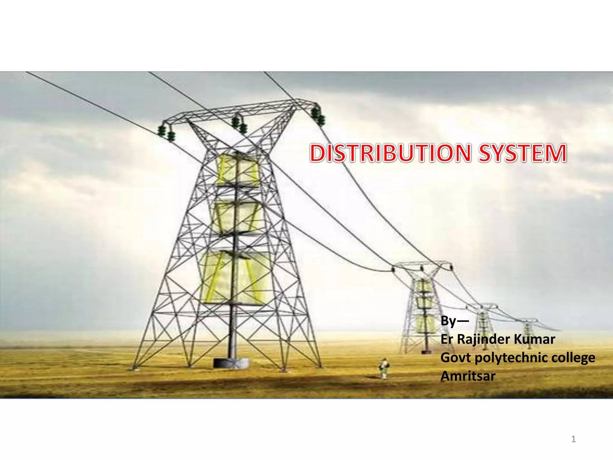
The document discusses various components of power distribution systems including substations, transmission lines, and distribution lines. It provides details on:
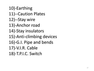
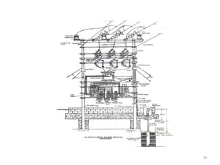
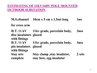
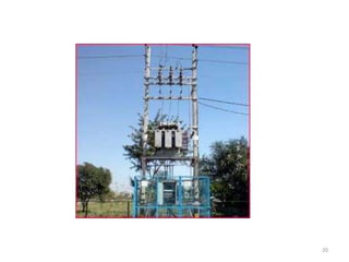
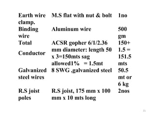
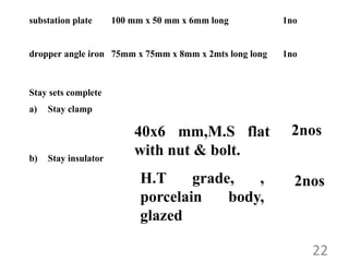
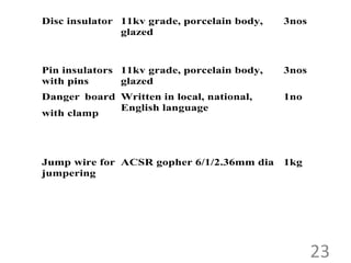
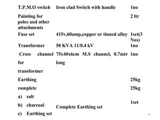
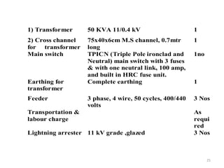
1) The components of a pole mounted substation, including the pole structure, transformer, insulators, switches, and earthing equipment.
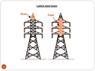
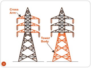
2) The components of lattice steel transmission towers, including the peak, cross arms, body, and foundation.
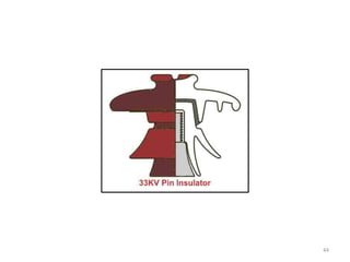
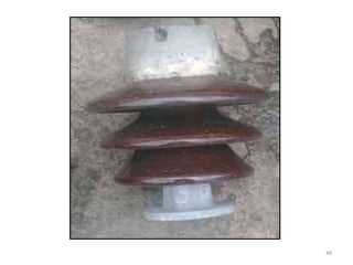
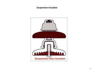
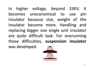
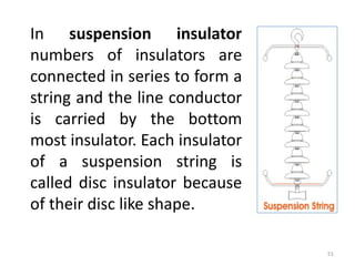
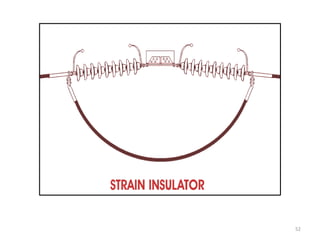
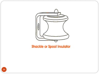
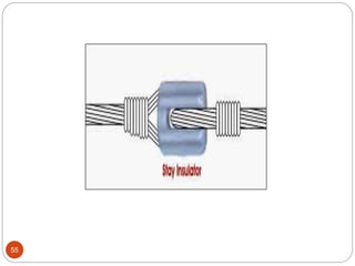
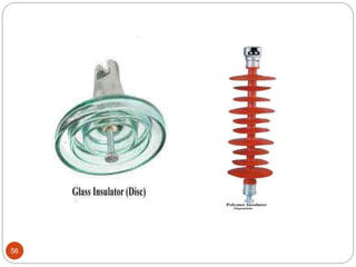
3) Types of insulators used in distribution systems, including pin, post, disc, and suspension string insulators.


![[IoT] MAKE with Open H/W + Node.JS - 4th](https://cdn.slidesharecdn.com/ss_thumbnails/iotoshwnodejslesson4-150419161845-conversion-gate02-thumbnail.jpg?width=640&height=640&fit=bounds)


