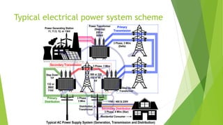
HIGH VOLTAGE AC
TRANSMISSION
An electric power system or electric grid is known as a large network of
power generating plants which connected to the consumer loads.
As, it is well known that “Energy cannot be created nor be destroyed but
can only be converted from one form of energy to another form of energy”
Electrical energy is a form of energy where we transfer this energy in the
form of flow of electron. So, electrical energy is obtained by converting
various other forms of energy.
The main objective of an electric power system is to obtain electrical energy
and make it reachable safely to the load point where it is being used in
usable form. This is done in five stages namely
1. Generating Station
2. Primary Transmission
3. Secondary Transmission
4. Primary Distribution
5. Secondary Distribution
What is an Electric Power System?
Layout of Power System Network
Generation or Generating Station
 The place where electric power produced by the parallel connected three
phase alternators/generators is called Generating Station (i.e. power plant).
 The ordinary power plant capacity and generating voltage may be 11kV, 11.5
kV 12kV or 13kV. But economically, it is good to step up the produced voltage
from (11kV, 11.5kV Or 12 kV) to 132kV, 220kV or 500kV or more (in some
countries, up to 1500kV) by Step up transformer (power Transformer).
 Generation is the part of power system where we convert some form of
energy into electrical energy. This is the source of energy in the power
system. It keeps running all the time. It generates power at different voltage
and power levels depending upon the type of station and the generators used.
The maximum number of generators generate the power at voltage level
around 11kV-20kV. The increased voltage level leads to greater size of
generator required and hence the cost involved.
Advantage of Interconnection of Generating
Stations
The power system consists two or more generating stations which are connected by
tie lines. Interconnection of generating stations has the following important
advantages.
 It enables the mutual transfer of energy from surplus zone to deficit zone
economically.
 Lesser overall installed capacity to meet the peak demand.
 Lesser standby reserve generating capacity is required.
 It permits the generation of energy at the most efficient and cheapest station at
every time.
 It reduces the capital cost, operating cost and cost of energy generated.
 If there is a major breakdown of a generating system unit in an interconnected
system, then there is no interruption of power supply.
PrimaryTransmission
 The electric supply (in 132kV, 220 kV, 500kV or greater) is transmitted
to load center by three phase three wire (3 Phase – 3 Wires also
known as Delta connection) overhead transmission system.
 As the voltage level which is generated is around (11-20) kV and the
demand is at various levels of voltage and at very far away places
from the generating station. For example, the generating station can
be generating voltage at 11kv, but the load center is 1000km apart
and at the level of 440V.
 Therefore, for the delivery of electrical energy at such a long
distance, an arrangement must be there to make it possible. Hence,
the transmission system is essential for the delivery of electrical
energy. This is made possible by using the transmission lines of
different length. These are overhead transmission lines in almost
every cases. Some exceptions occur when it is needed to cross an
ocean. Then there is a compulsion to use underground cables.
 But, as the system grew and load demand increased, the challenge in
this process has become very complex. At low voltage level, the
amount of current flowing through the line for high load demand is
more and hence the voltage drop due to the resistance and reactance
of the transmission line is very significant. This leads to more losses in
the transmission lines and the decrease in the voltage at the load end.
 This affects the cost of the system and the working of the equipment
the consumers use. So, transformer is used to increase the voltage
level at certain values ranging from 220kV to 765kV. This makes the
current value lesser for the same load that would be having higher
values of current at certain load.
Secondary Transmission
Area far from the city (outskirts) which have connected with
receiving stations by lines is called secondary transmission.
At receiving station, the level of voltage reduced by step-
down transformers up to 132kV, 66 or 33 kV, and electric
power is transferred by three phase three wire (3 Phase – 3
Wires) overhead system to different sub stations.
PrimaryDistribution
 At a sub station, the level of secondary transmission voltage (132kV,
66 or 33 kV) reduced to 11kV by step down transforms.
 Generally, electric supply is provided to those heavy load consumer
(commercial power supply for industries) where the demands is 11 kV,
from the lines which caries 11kV ( in three phase three wire overhead
system) and they make a separate sub station to control and utilize
the heavy power in industries and factories.
 In other cases for heavier load consumers (at large scale), the demand
is upto132 kV or 33 kV. So electric supply provided them directly by
secondary transmission or primary distribution (in 132 kV, 66kV or
33kV) and then step down the level of voltage by step-down
transformers in their own sub station for utilization ( i.e. for electric
traction etc).
 Many control mechanisms are provided in the substations to make the
power delivery a controlled and continuous process without much
disturbance. These substations deliver power to smaller units called
‘Feeders’. This is done by either ‘Overhead lines’ or ‘Underground cables’.
These feeders are in towns, cities, or villages or it may be some group of
industries, which takes the power from the substation, and convert its
voltage level according to its own use.
 For domestic use, the voltage is further reduced at 110V-230V (phase to
ground) to be used by the individuals at different power factor. The
combined amount of demand is the load on the entire system and that
must be generated at that instant.
SECONDARY DISTRIBUTION
Electric power is transferred by (from primary distribution line i.e.11kV) to
distribution sub station is known as secondary distribution. This sub station is
located near by domestic & consumers areas where the level of voltage reduced
to 440V by step down transformers.
These transformers called Distribution transformers, three phase four wire
system (3 Phase – 4 Wires also known as Star connection). So there is 400 Volts
(Three Phase Supply System) between any two phases and 230 Volts (Single Phase
Supply) between a neutral and phase (live) wires.
Residential load (i.e. Fans, Lights, and TV etc) may be connected between any
one phase and neutral wires, while three phase load may be connected directly
to the three phase lines.
In short, secondary power distribution may be divided in three sections such as ,
feeders, distributors and service lines (details below).
Elements of a Distribution System
Secondary distribution may be divided into three parts as follow.
 Feeders
 Distributors
 Service Lines or Service Mains
 Feeders
Those electric power lines which connect generating station (power
station) or sub station to distributors are called feeders. Remember that
current in feeders (in each point) is constant while the level of voltage may
be different. The current flowing in the feeders depends on the size of
conductor.
 Distributors
 Those taping which extracted for electric power supply to the consumers or
the lines, from where consumers get direct electric power supply is known as
distributors . Current is different in each section of the distributors while
voltage may be same. The selection of distributors depends on voltage drop
and may be design according different level of voltage drops. It is because
consumers should get the rated voltage according to the rules and design.
 Service lines or Service mains
 The normal cable which is connected between Distributors and Consumer load
terminal called Service Line or Service Mains. in other words, the cable which
has been connected to the 11kV power lines (taken from step down
transformer) to get three phase or single phase power supply. Phase or Live to
Neutral power is 230V AC (110 in US) and 440V AC (208 in US) in three phase
(phase to phase) system.
Combined Process of Power System
The entire structure of the power system is consisting of the source (Generating
station), transfer (Transmission and Distribution) and the load (Consumer). The
objectives are:-
 Rated voltage and frequency to the load centres.
 Reliability of the system so that power delivery is continuous.
 Flexibility of the system so that the power is available at different voltage
levels
 Faster clearance of faults so that the runs well for longer time and it life
elongates
 The cost of power must be as low as possible
 The losses in the system must be as low as possible
Typical electrical power system scheme
Working Voltage
There is a desirability of High Voltage if the power is to be transmitted over a long
distance. It is also necessary that with the AC systems the load power factor
should be as near to Unity as possible for maximum efficiency .
It is to be noted heavy currents are more difficult to handle than high voltages.
Considerable saving in the cost of conductive material is possible when the voltage
is high.
At high voltage is the cost of insulation of conductors, weather overhead
underground, increases appreciable. The problems encountered with high voltage
insulation of equipment, carona, radio and television interference.
The voltage level of the system is therefore, governed by the amount of power to
be transmitted and the length of line.
High voltage Transmission Advantages
• With increase in the transmission voltage size of the conductors is reduced
(Cross section of the conductors reduce as current required to carry reduces).
• As the reduction in current carrying requirement losses reduces results in better
efficiency. As it minimizes the power loss due to resistance in
conductohig,Power is dissipated as heat. The relationship between power,
current and resistance is P=I²R. The power loss in the transmission line is be
proportional to I²*T.
• Due to low current voltage drop will be less so voltage regulation improves
High voltage transmission Limitation
 With the increase in the voltage of transmission, the insulation required
between the conductors and the earthed tower increases. This increase the
cost of line support
 With increase in the voltage of transmission, more clearance is required
between conductors and ground. Hence higher towers are required.
 With increase in the voltage transmission, more distance is required between
the conductors. Therefore cross arms should be long

HIGH VOLTAGE AC TRANSMISSION.pptx

  • 1.
  • 2.
    An electric powersystem or electric grid is known as a large network of power generating plants which connected to the consumer loads. As, it is well known that “Energy cannot be created nor be destroyed but can only be converted from one form of energy to another form of energy” Electrical energy is a form of energy where we transfer this energy in the form of flow of electron. So, electrical energy is obtained by converting various other forms of energy. The main objective of an electric power system is to obtain electrical energy and make it reachable safely to the load point where it is being used in usable form. This is done in five stages namely 1. Generating Station 2. Primary Transmission 3. Secondary Transmission 4. Primary Distribution 5. Secondary Distribution What is an Electric Power System?
  • 3.
    Layout of PowerSystem Network
  • 4.
    Generation or GeneratingStation  The place where electric power produced by the parallel connected three phase alternators/generators is called Generating Station (i.e. power plant).  The ordinary power plant capacity and generating voltage may be 11kV, 11.5 kV 12kV or 13kV. But economically, it is good to step up the produced voltage from (11kV, 11.5kV Or 12 kV) to 132kV, 220kV or 500kV or more (in some countries, up to 1500kV) by Step up transformer (power Transformer).  Generation is the part of power system where we convert some form of energy into electrical energy. This is the source of energy in the power system. It keeps running all the time. It generates power at different voltage and power levels depending upon the type of station and the generators used. The maximum number of generators generate the power at voltage level around 11kV-20kV. The increased voltage level leads to greater size of generator required and hence the cost involved.
  • 5.
    Advantage of Interconnectionof Generating Stations The power system consists two or more generating stations which are connected by tie lines. Interconnection of generating stations has the following important advantages.  It enables the mutual transfer of energy from surplus zone to deficit zone economically.  Lesser overall installed capacity to meet the peak demand.  Lesser standby reserve generating capacity is required.  It permits the generation of energy at the most efficient and cheapest station at every time.  It reduces the capital cost, operating cost and cost of energy generated.  If there is a major breakdown of a generating system unit in an interconnected system, then there is no interruption of power supply.
  • 6.
    PrimaryTransmission  The electricsupply (in 132kV, 220 kV, 500kV or greater) is transmitted to load center by three phase three wire (3 Phase – 3 Wires also known as Delta connection) overhead transmission system.  As the voltage level which is generated is around (11-20) kV and the demand is at various levels of voltage and at very far away places from the generating station. For example, the generating station can be generating voltage at 11kv, but the load center is 1000km apart and at the level of 440V.  Therefore, for the delivery of electrical energy at such a long distance, an arrangement must be there to make it possible. Hence, the transmission system is essential for the delivery of electrical energy. This is made possible by using the transmission lines of different length. These are overhead transmission lines in almost every cases. Some exceptions occur when it is needed to cross an ocean. Then there is a compulsion to use underground cables.
  • 7.
     But, asthe system grew and load demand increased, the challenge in this process has become very complex. At low voltage level, the amount of current flowing through the line for high load demand is more and hence the voltage drop due to the resistance and reactance of the transmission line is very significant. This leads to more losses in the transmission lines and the decrease in the voltage at the load end.  This affects the cost of the system and the working of the equipment the consumers use. So, transformer is used to increase the voltage level at certain values ranging from 220kV to 765kV. This makes the current value lesser for the same load that would be having higher values of current at certain load.
  • 8.
    Secondary Transmission Area farfrom the city (outskirts) which have connected with receiving stations by lines is called secondary transmission. At receiving station, the level of voltage reduced by step- down transformers up to 132kV, 66 or 33 kV, and electric power is transferred by three phase three wire (3 Phase – 3 Wires) overhead system to different sub stations.
  • 9.
    PrimaryDistribution  At asub station, the level of secondary transmission voltage (132kV, 66 or 33 kV) reduced to 11kV by step down transforms.  Generally, electric supply is provided to those heavy load consumer (commercial power supply for industries) where the demands is 11 kV, from the lines which caries 11kV ( in three phase three wire overhead system) and they make a separate sub station to control and utilize the heavy power in industries and factories.  In other cases for heavier load consumers (at large scale), the demand is upto132 kV or 33 kV. So electric supply provided them directly by secondary transmission or primary distribution (in 132 kV, 66kV or 33kV) and then step down the level of voltage by step-down transformers in their own sub station for utilization ( i.e. for electric traction etc).
  • 10.
     Many controlmechanisms are provided in the substations to make the power delivery a controlled and continuous process without much disturbance. These substations deliver power to smaller units called ‘Feeders’. This is done by either ‘Overhead lines’ or ‘Underground cables’. These feeders are in towns, cities, or villages or it may be some group of industries, which takes the power from the substation, and convert its voltage level according to its own use.  For domestic use, the voltage is further reduced at 110V-230V (phase to ground) to be used by the individuals at different power factor. The combined amount of demand is the load on the entire system and that must be generated at that instant.
  • 11.
    SECONDARY DISTRIBUTION Electric poweris transferred by (from primary distribution line i.e.11kV) to distribution sub station is known as secondary distribution. This sub station is located near by domestic & consumers areas where the level of voltage reduced to 440V by step down transformers. These transformers called Distribution transformers, three phase four wire system (3 Phase – 4 Wires also known as Star connection). So there is 400 Volts (Three Phase Supply System) between any two phases and 230 Volts (Single Phase Supply) between a neutral and phase (live) wires. Residential load (i.e. Fans, Lights, and TV etc) may be connected between any one phase and neutral wires, while three phase load may be connected directly to the three phase lines. In short, secondary power distribution may be divided in three sections such as , feeders, distributors and service lines (details below).
  • 12.
    Elements of aDistribution System Secondary distribution may be divided into three parts as follow.  Feeders  Distributors  Service Lines or Service Mains  Feeders Those electric power lines which connect generating station (power station) or sub station to distributors are called feeders. Remember that current in feeders (in each point) is constant while the level of voltage may be different. The current flowing in the feeders depends on the size of conductor.
  • 13.
     Distributors  Thosetaping which extracted for electric power supply to the consumers or the lines, from where consumers get direct electric power supply is known as distributors . Current is different in each section of the distributors while voltage may be same. The selection of distributors depends on voltage drop and may be design according different level of voltage drops. It is because consumers should get the rated voltage according to the rules and design.  Service lines or Service mains  The normal cable which is connected between Distributors and Consumer load terminal called Service Line or Service Mains. in other words, the cable which has been connected to the 11kV power lines (taken from step down transformer) to get three phase or single phase power supply. Phase or Live to Neutral power is 230V AC (110 in US) and 440V AC (208 in US) in three phase (phase to phase) system.
  • 14.
    Combined Process ofPower System The entire structure of the power system is consisting of the source (Generating station), transfer (Transmission and Distribution) and the load (Consumer). The objectives are:-  Rated voltage and frequency to the load centres.  Reliability of the system so that power delivery is continuous.  Flexibility of the system so that the power is available at different voltage levels  Faster clearance of faults so that the runs well for longer time and it life elongates  The cost of power must be as low as possible  The losses in the system must be as low as possible
  • 15.
  • 16.
    Working Voltage There isa desirability of High Voltage if the power is to be transmitted over a long distance. It is also necessary that with the AC systems the load power factor should be as near to Unity as possible for maximum efficiency . It is to be noted heavy currents are more difficult to handle than high voltages. Considerable saving in the cost of conductive material is possible when the voltage is high. At high voltage is the cost of insulation of conductors, weather overhead underground, increases appreciable. The problems encountered with high voltage insulation of equipment, carona, radio and television interference. The voltage level of the system is therefore, governed by the amount of power to be transmitted and the length of line.
  • 17.
    High voltage TransmissionAdvantages • With increase in the transmission voltage size of the conductors is reduced (Cross section of the conductors reduce as current required to carry reduces). • As the reduction in current carrying requirement losses reduces results in better efficiency. As it minimizes the power loss due to resistance in conductohig,Power is dissipated as heat. The relationship between power, current and resistance is P=I²R. The power loss in the transmission line is be proportional to I²*T. • Due to low current voltage drop will be less so voltage regulation improves
  • 18.
    High voltage transmissionLimitation  With the increase in the voltage of transmission, the insulation required between the conductors and the earthed tower increases. This increase the cost of line support  With increase in the voltage of transmission, more clearance is required between conductors and ground. Hence higher towers are required.  With increase in the voltage transmission, more distance is required between the conductors. Therefore cross arms should be long