Download as PPSX, PPTX
![19
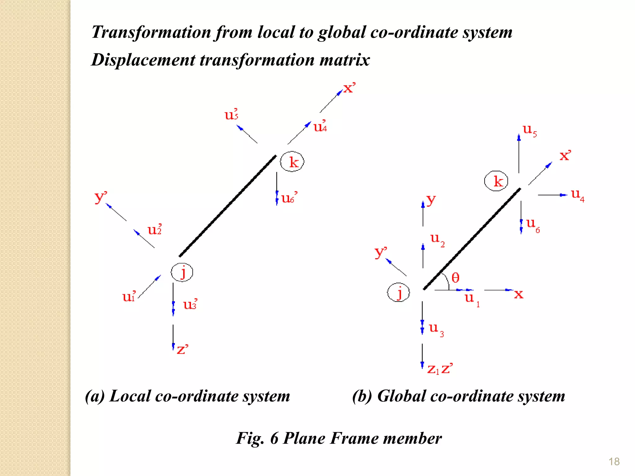
Let θ be the angle by which the member is inclined to global x-axis. From Fig. 6
a and b, one could relate u’1, u’2, u’3 to u1, u2, u3 as,
u’1 = u1 cosθ + u2 sinθ
u’2 = - u1 cosθ + u2 cosθ
u’3 = u3
This may be written as,
Where, l=cosθ and m=sinθ.
This may be written in compact form as,
{u’} = [T] {u} -----(1)](https://image.slidesharecdn.com/dissertation-report-160614044549/75/Dissertation-report-19-2048.jpg)
![20
Member global stiffness matrix
From above equation, we have
{q’} = [k’] {u’} -----(2)
Substituting the above value of { q’}
{p} = [T] T [k’] {u’}
{p} = [T] T [k’] [T] {u}
{p} = [k] {u}
{k} = [T] T [k] [T] ----(3)
The above equation represents global member stiffness matrix](https://image.slidesharecdn.com/dissertation-report-160614044549/75/Dissertation-report-20-2048.jpg)
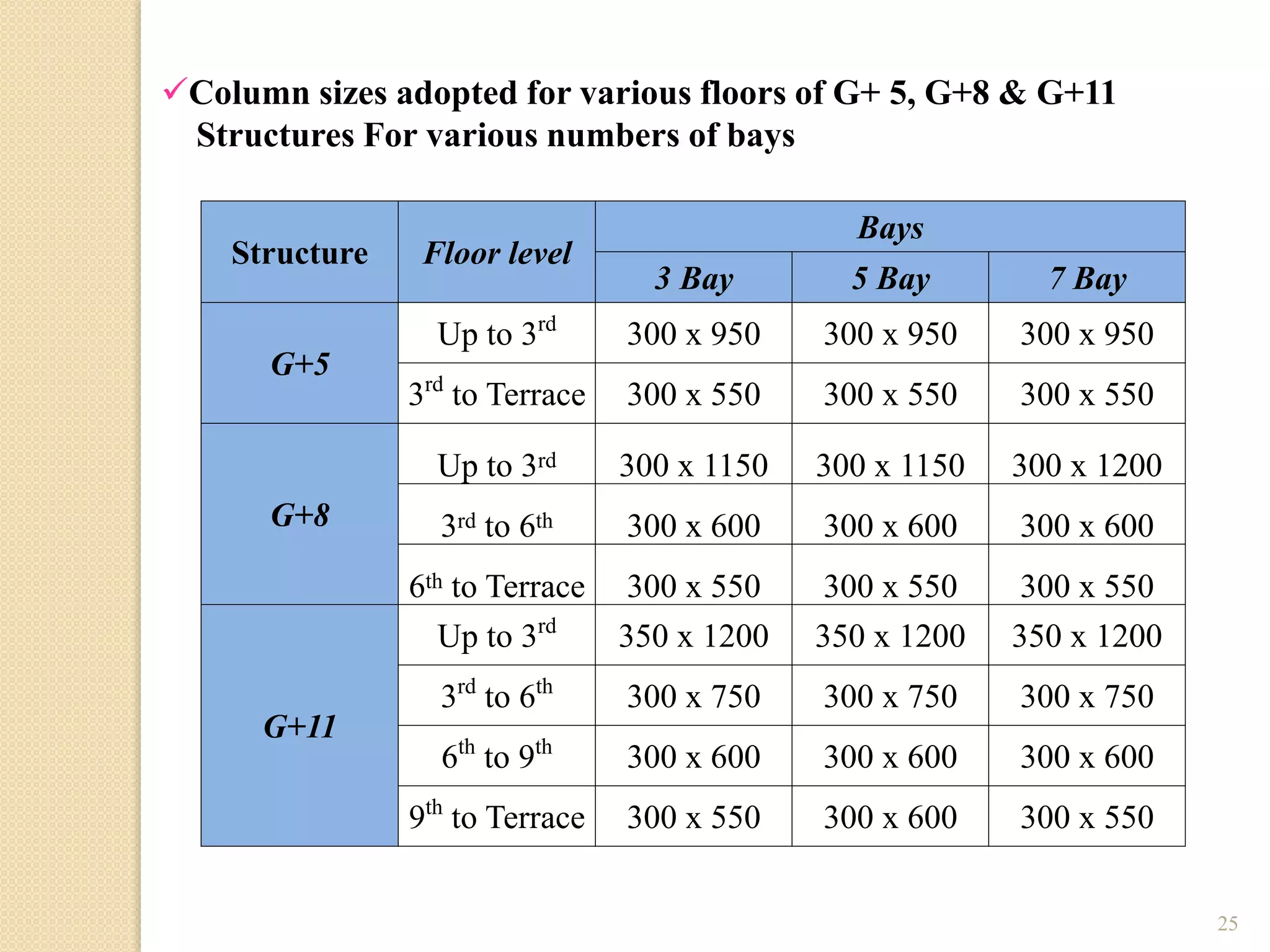
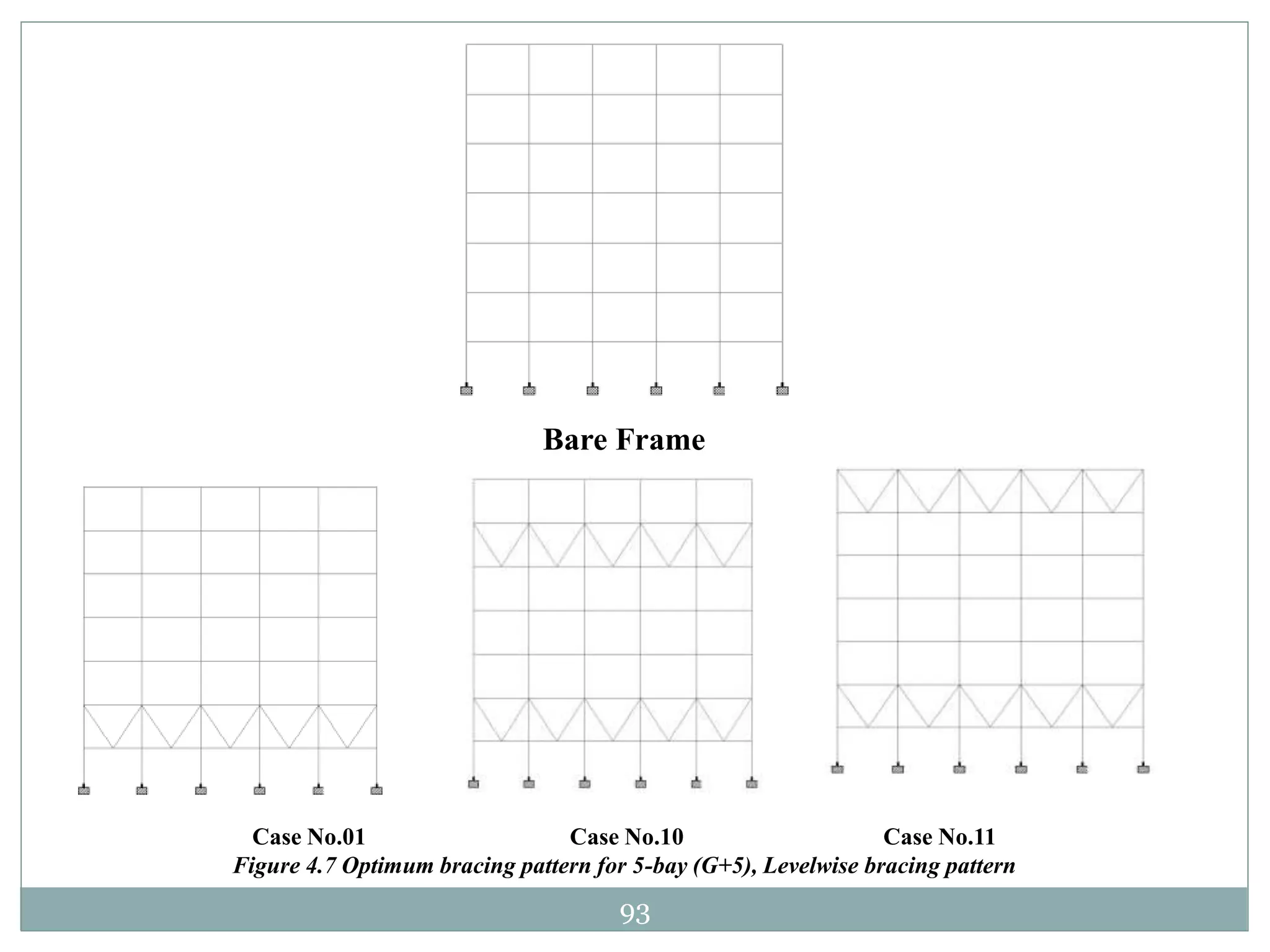
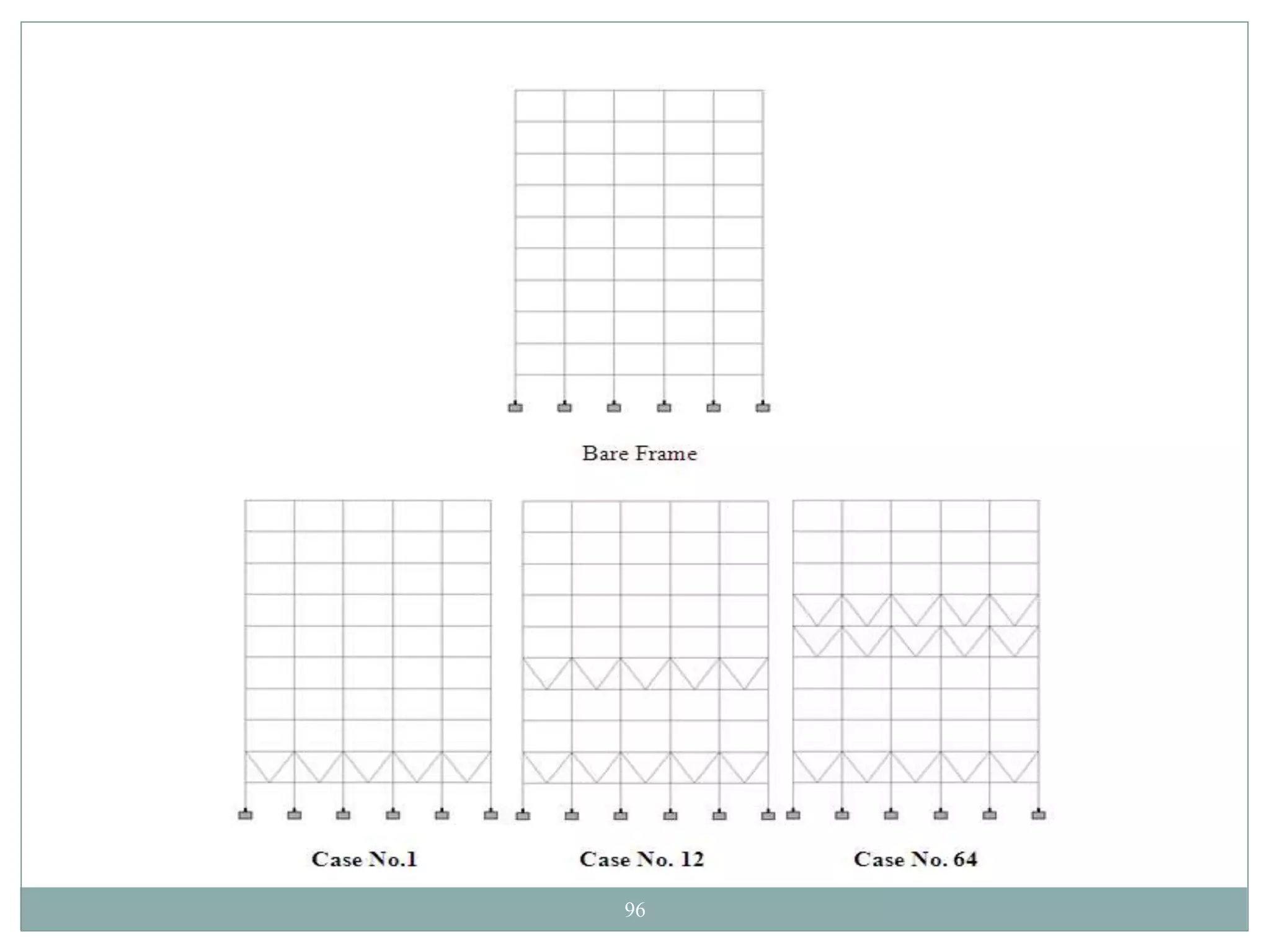
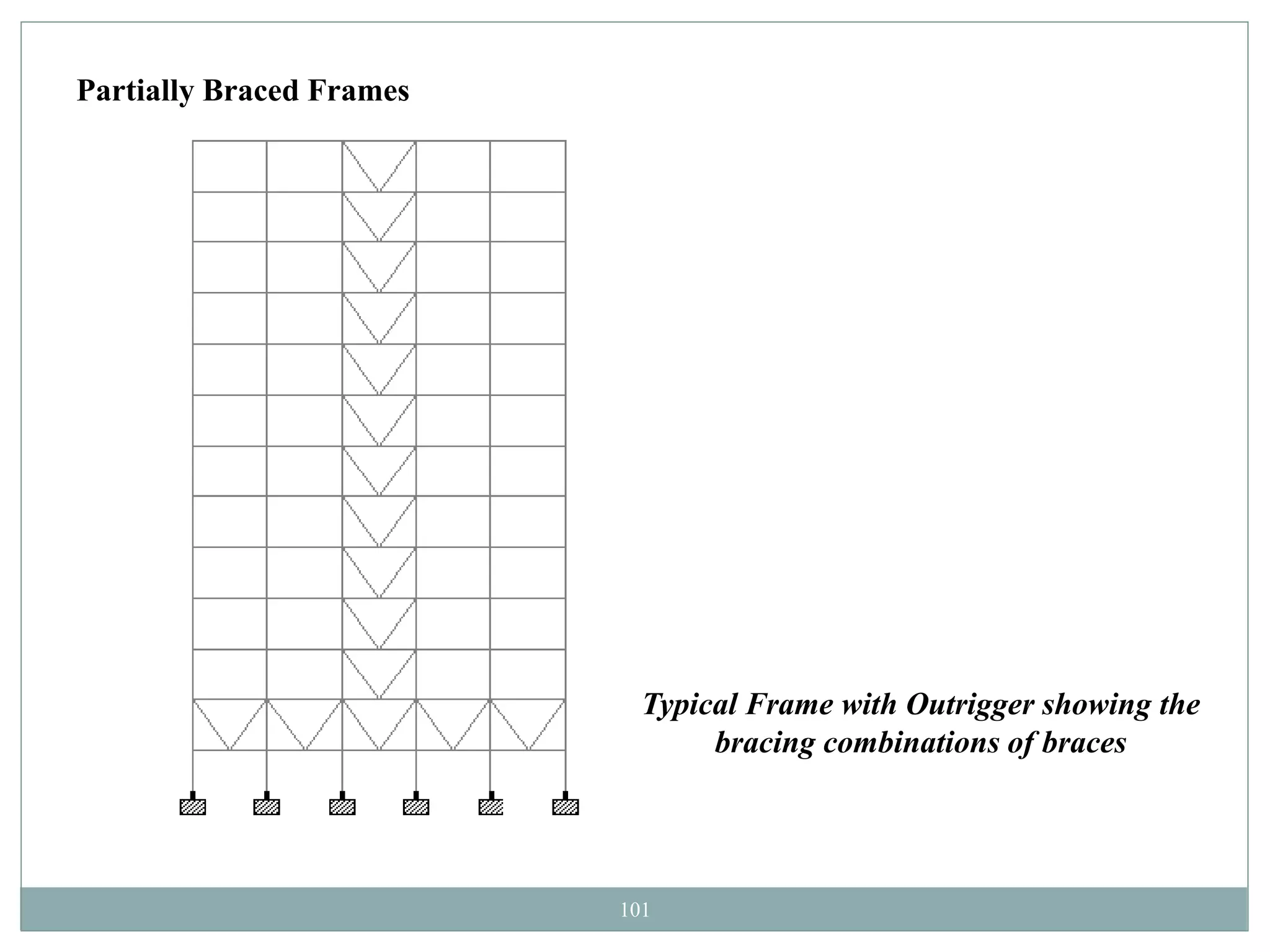
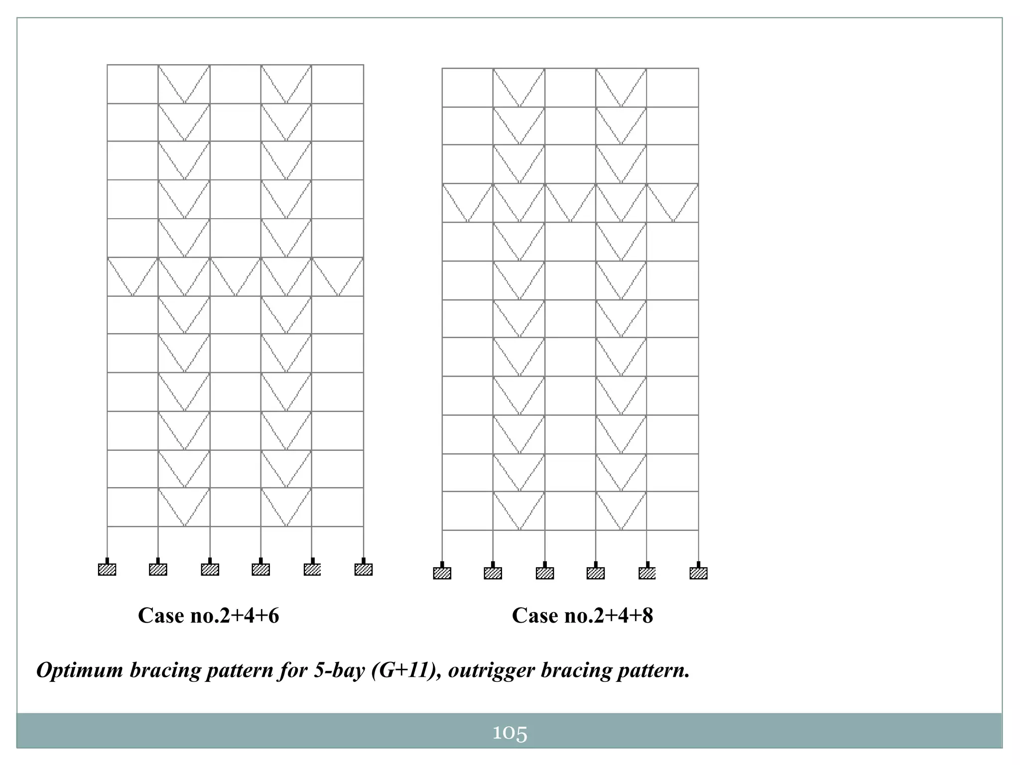
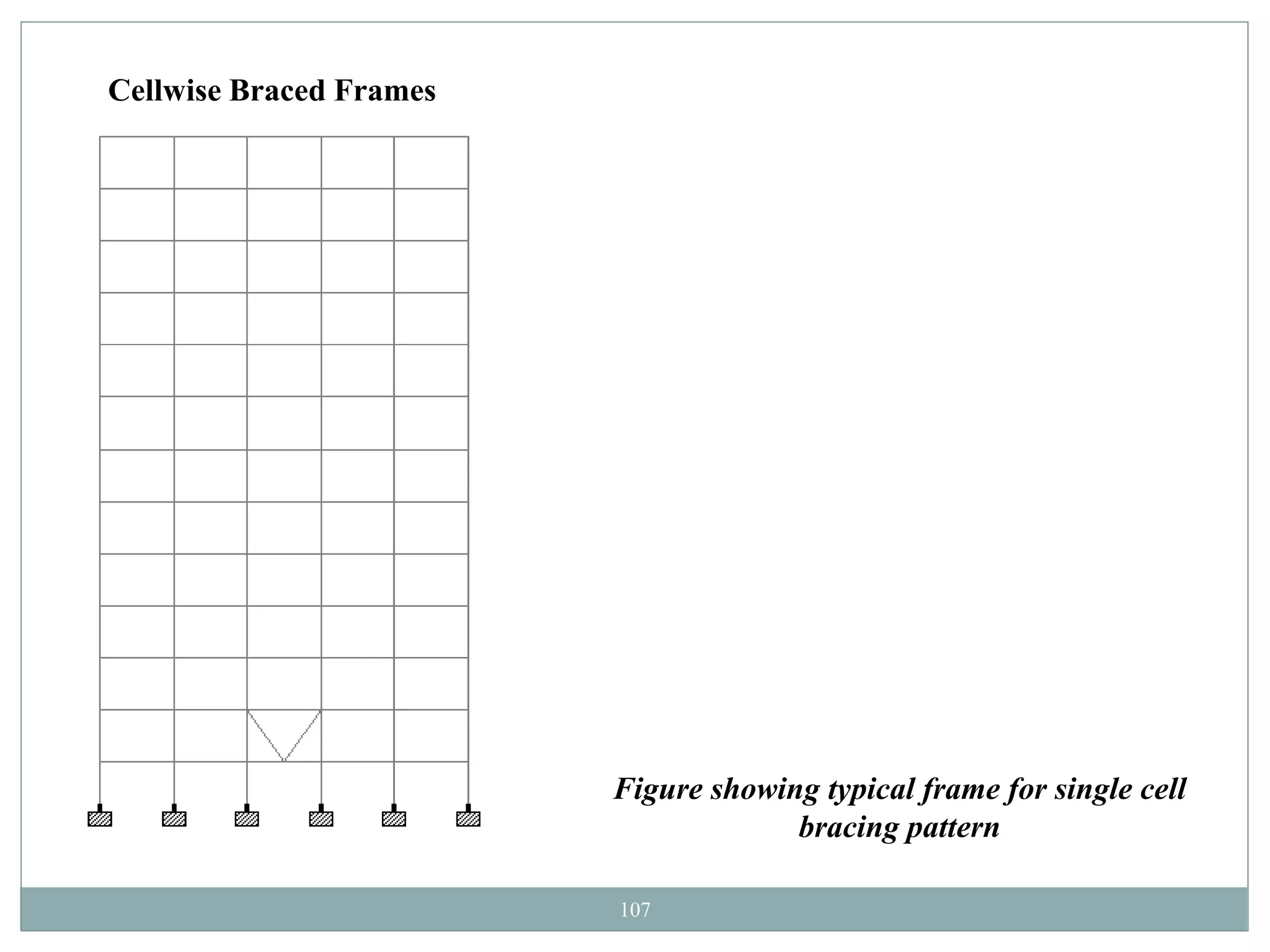
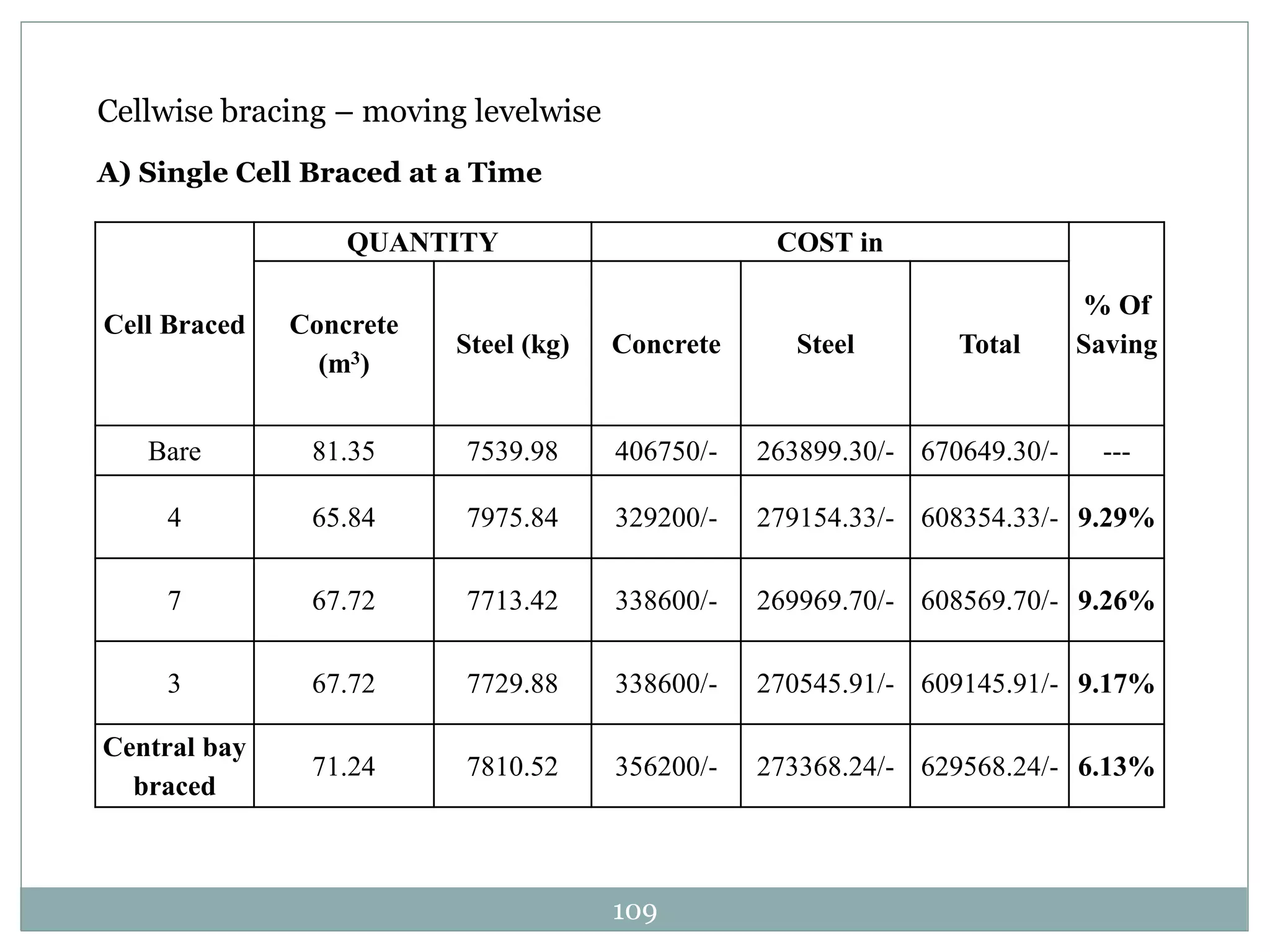
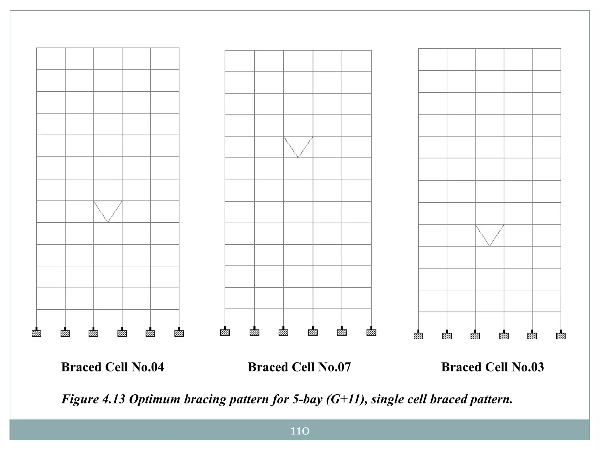
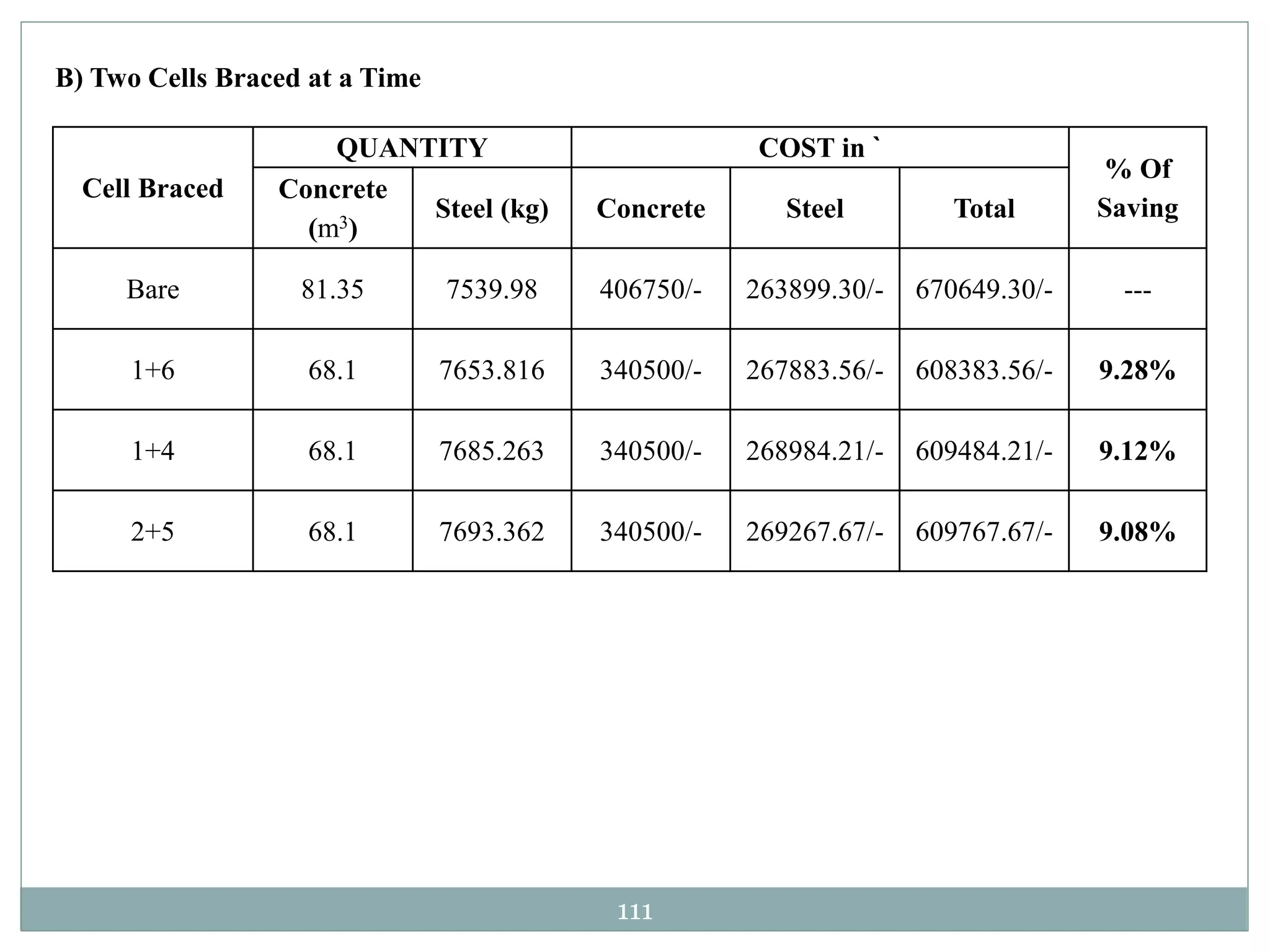
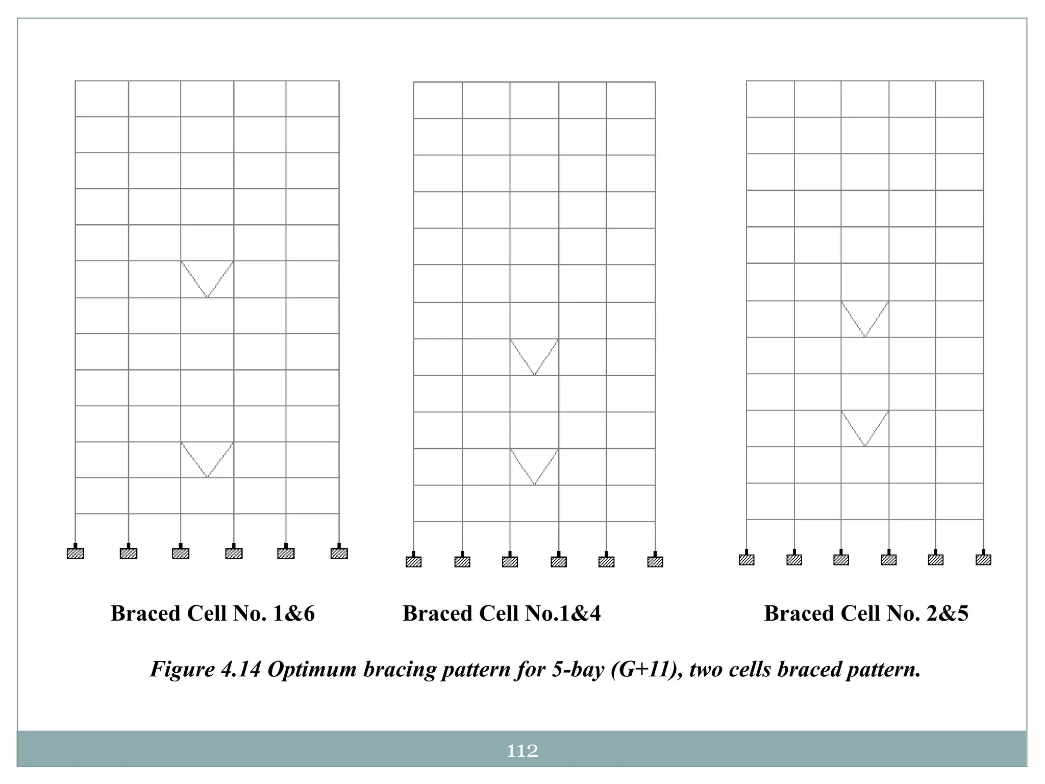
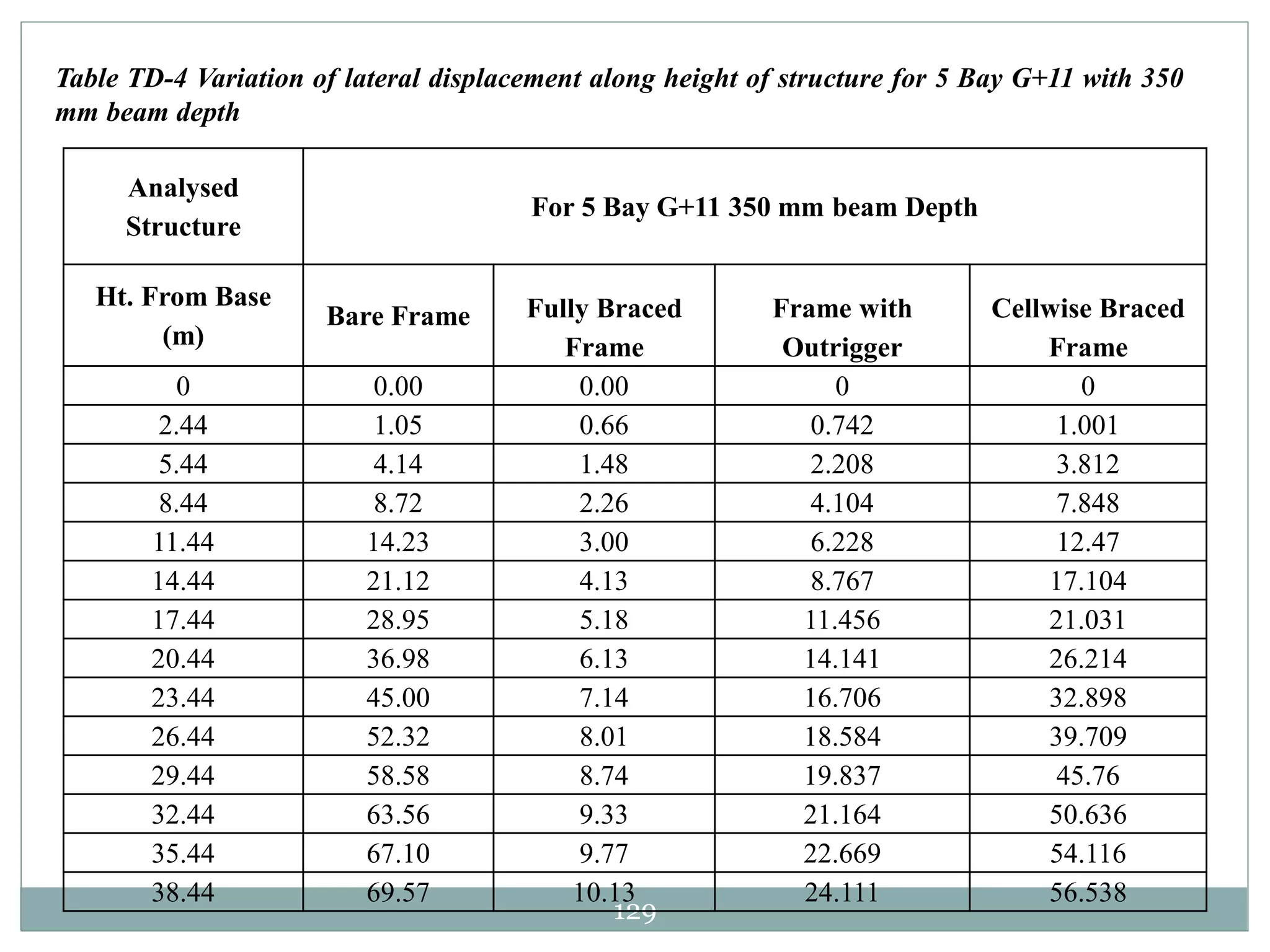
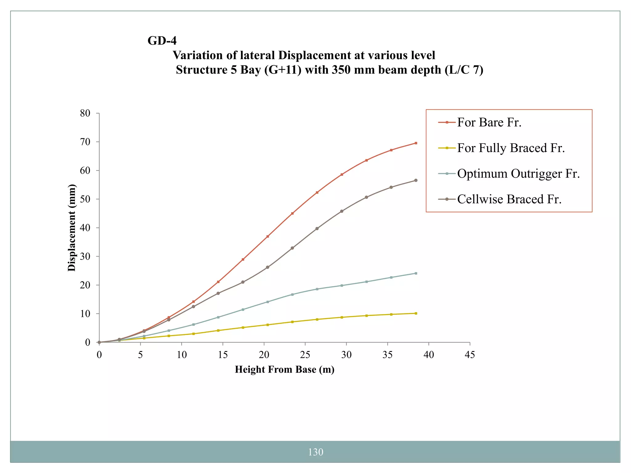


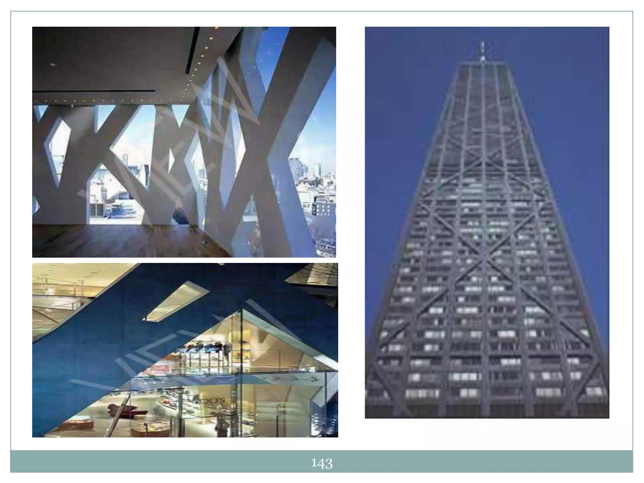
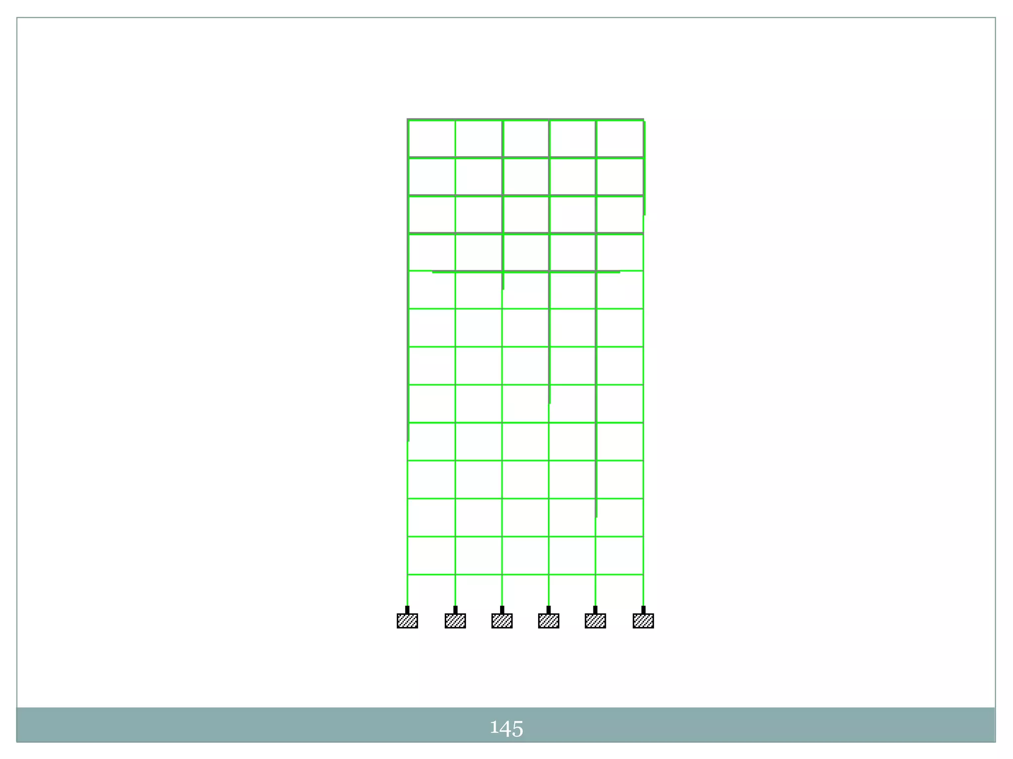

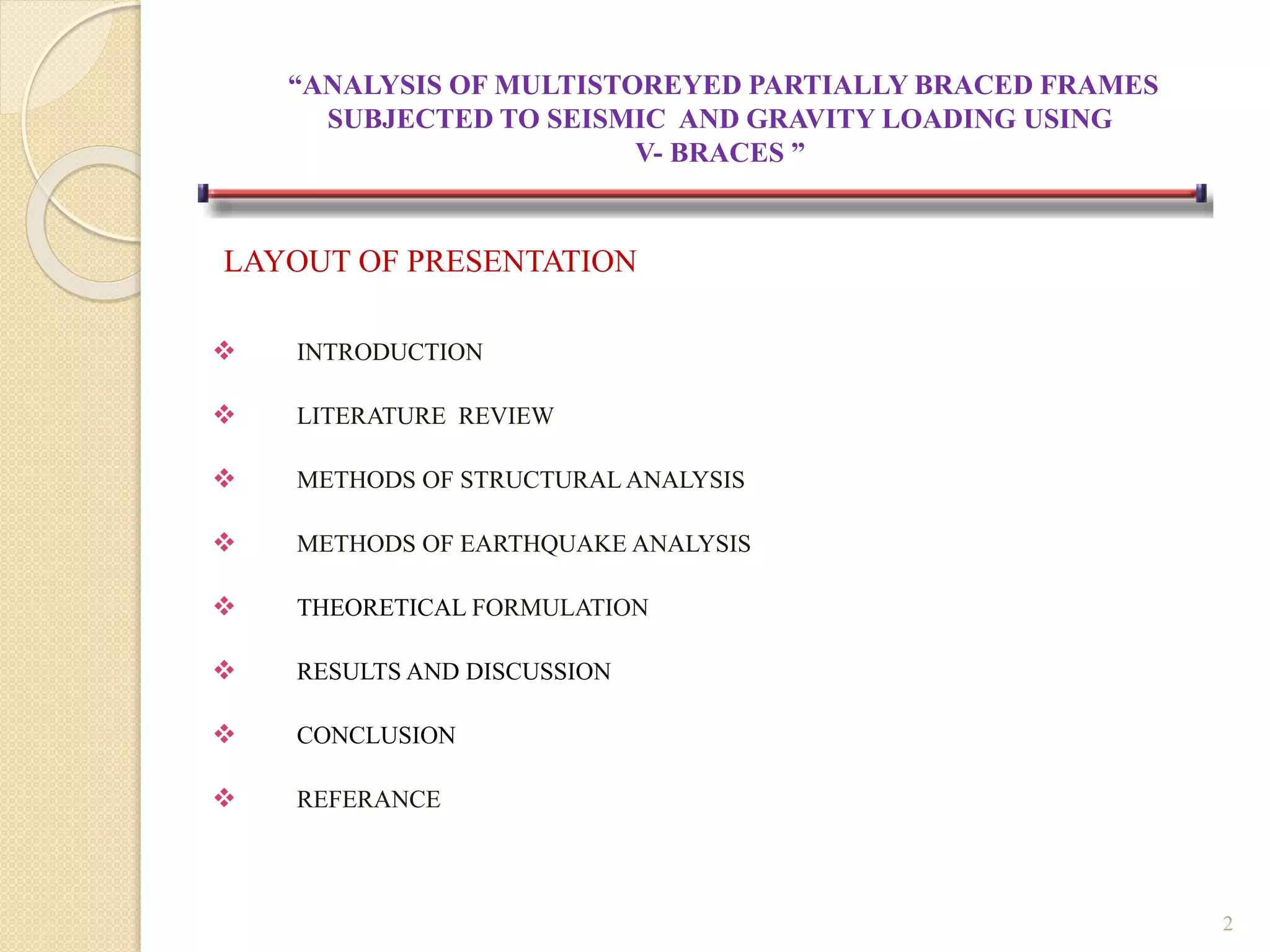
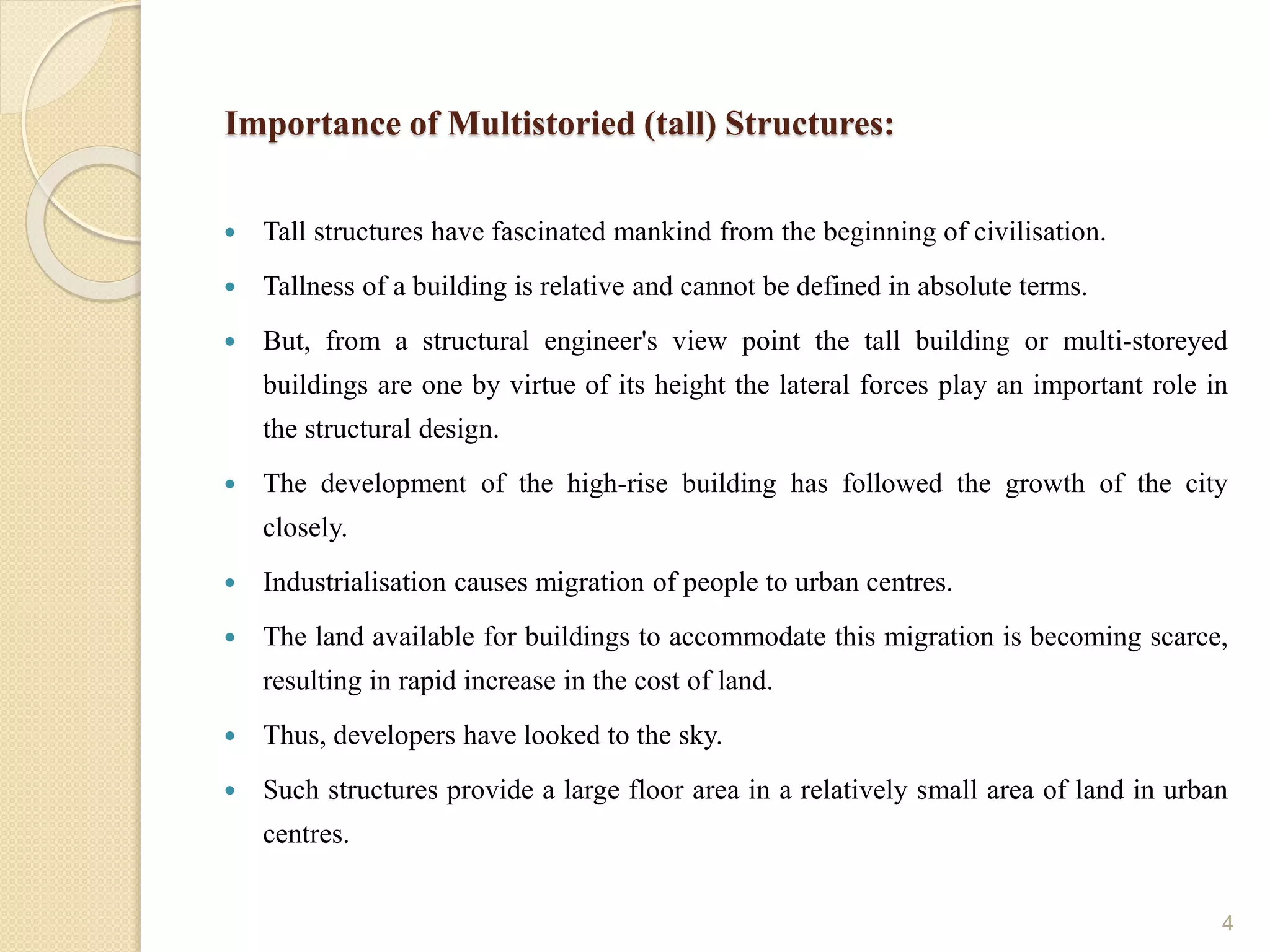
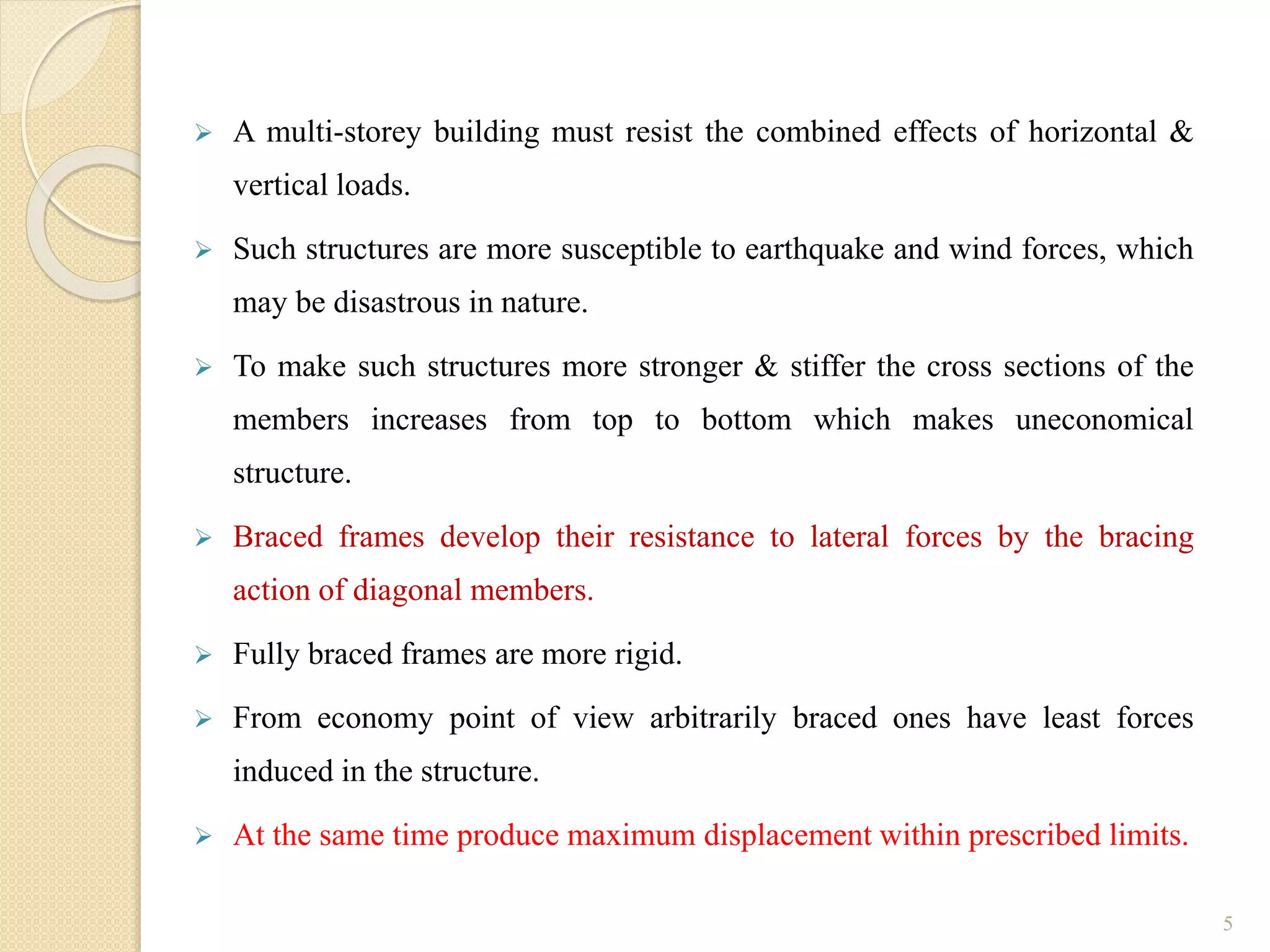
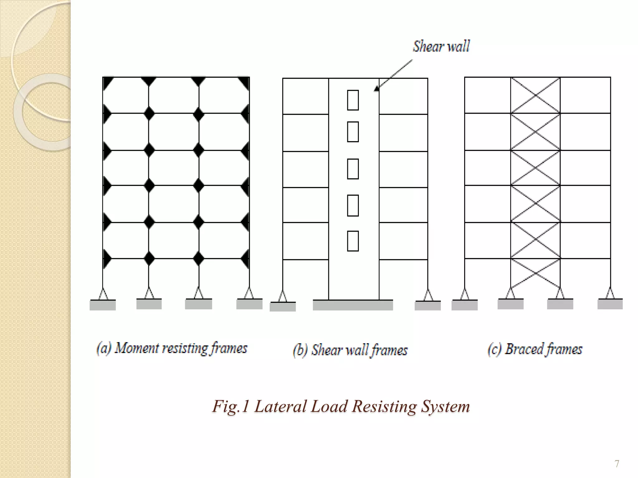
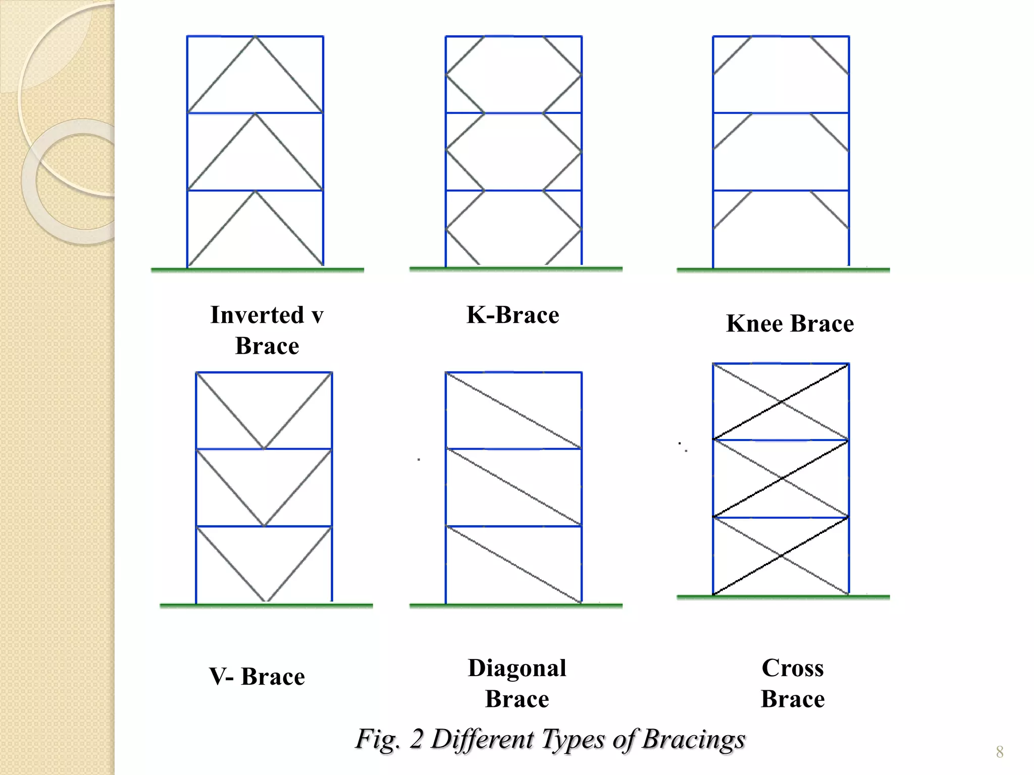
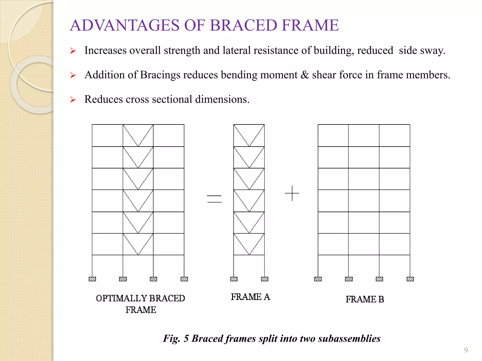
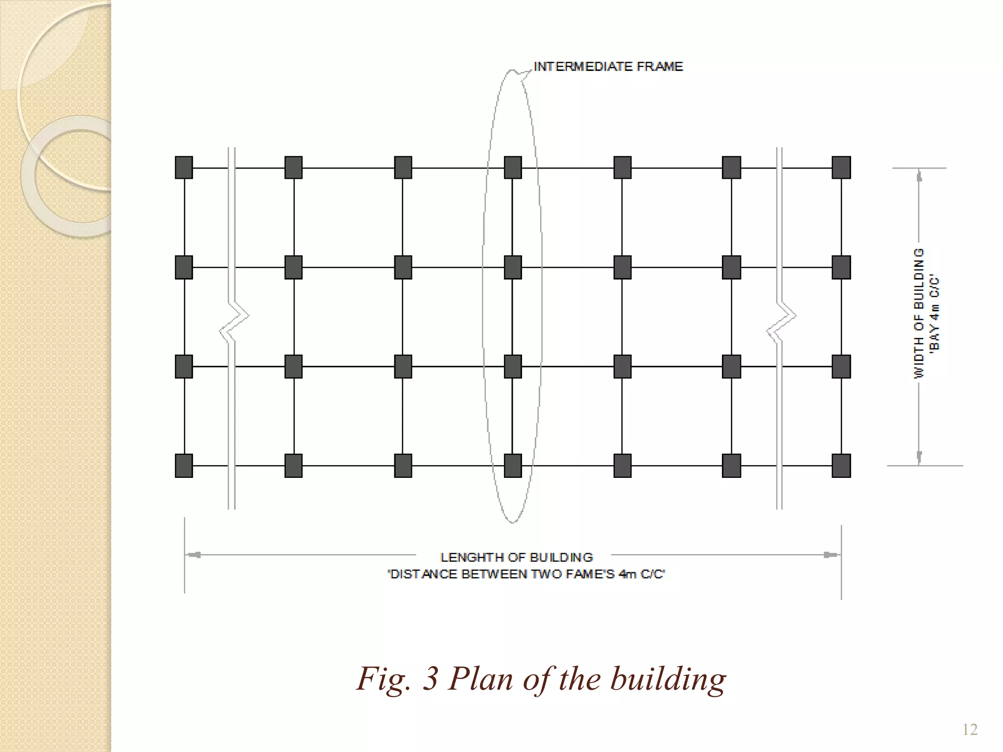
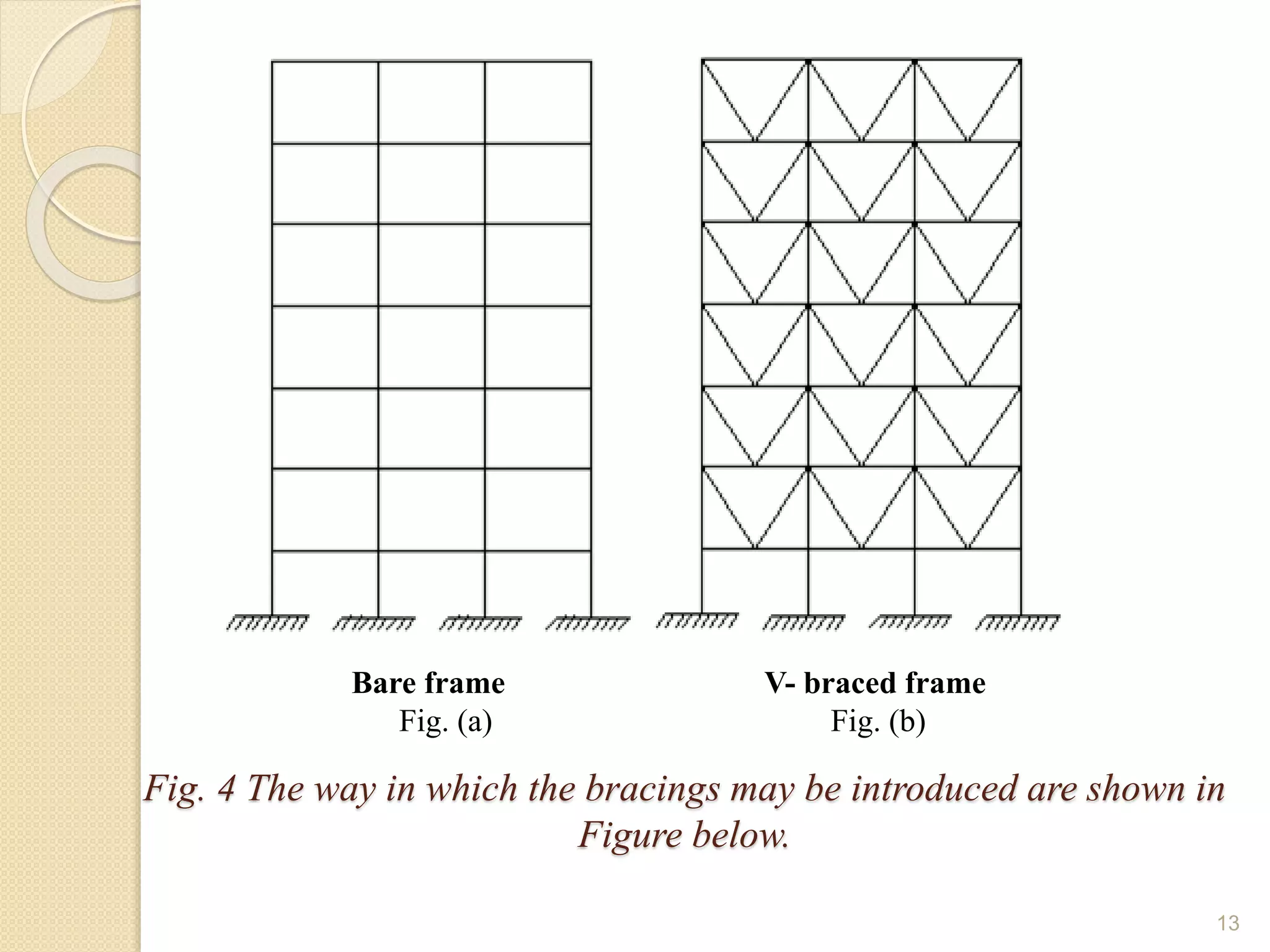
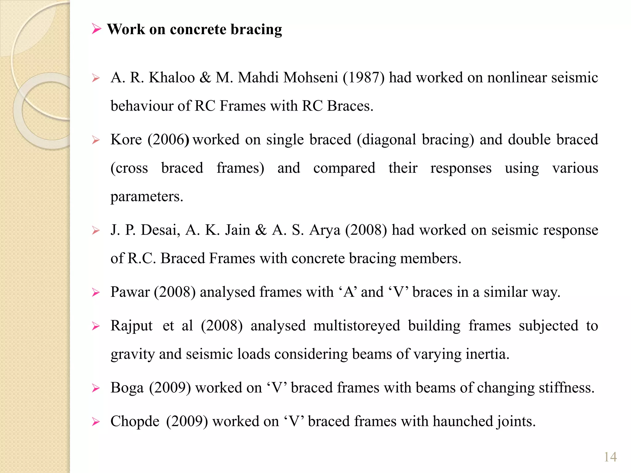
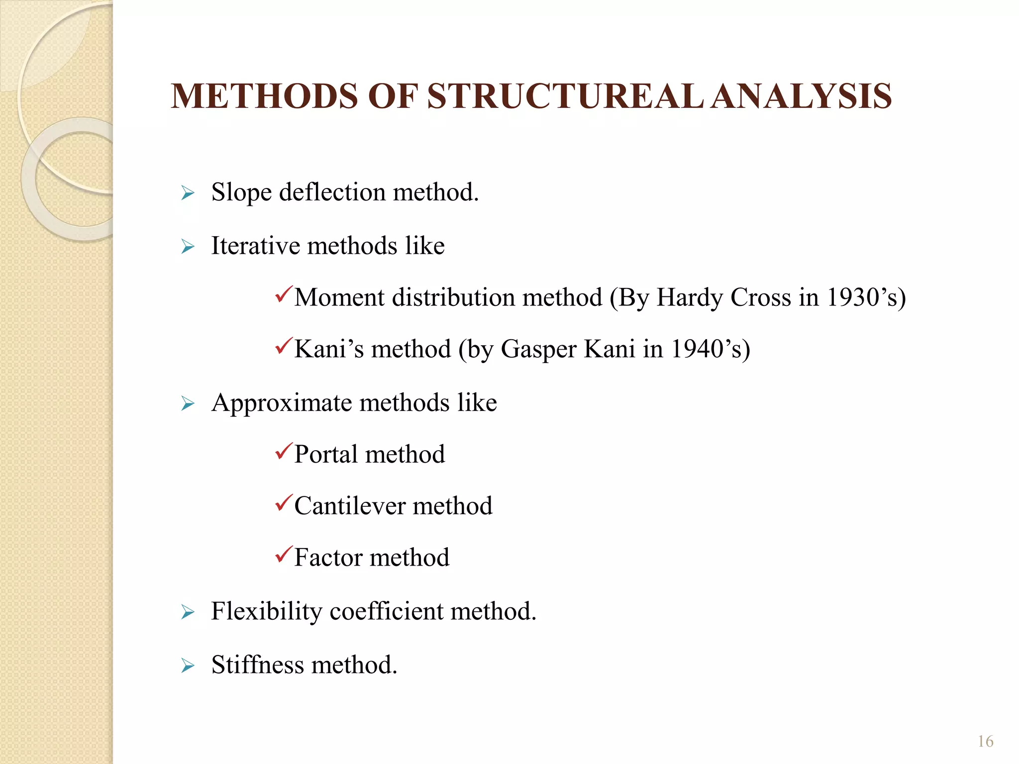
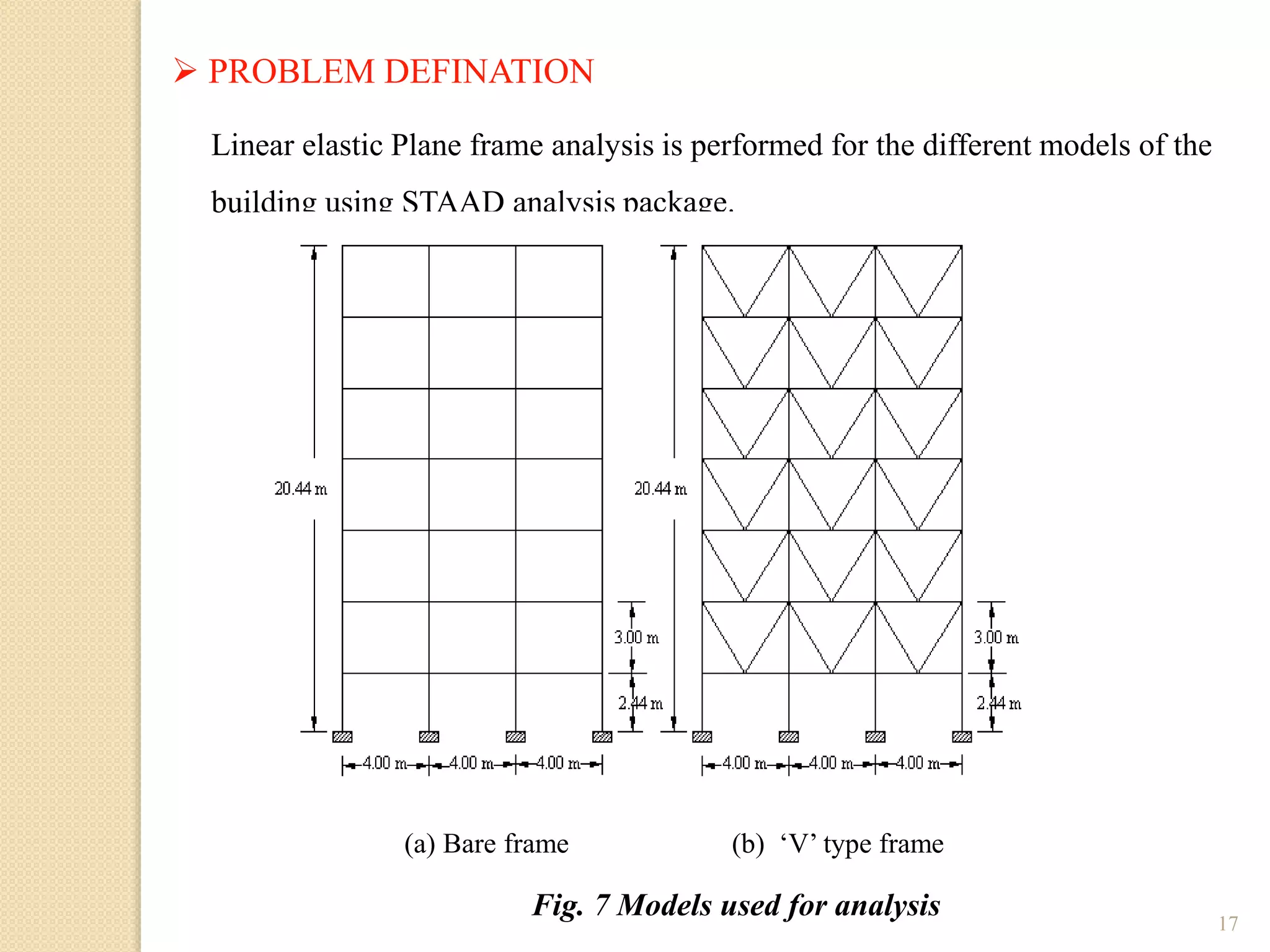
This document presents the layout and introduction for a dissertation report on analyzing multi-storey partially braced frames subjected to seismic and gravity loads using V-braces. The layout includes sections on introduction, literature review, structural analysis methods, earthquake analysis methods, theoretical formulation, results and discussion, conclusion, and references. The introduction discusses the importance of tall structures and braced frames, noting advantages of braced frames include increased strength, stiffness, and reduced member sizes.