Downloaded 67 times
![Engineering Structures 27 (2005) 951–962
www.elsevier.com/locate/engstruct
Seismic behaviors of columns in ordinary and intermediate moment
resisting concrete frames
Sang Whan Han∗, N.Y. Jee
Department of Architectural Engineering, Hanyang University, Seoul 133-791, Republic of Korea
Received 30 March 2004; received in revised form 31 January 2005; accepted 31 January 2005
Available online 10 March 2005
Abstract
The objective of this study was to investigate the seismic behaviors of columns in Ordinary Moment Resisting Concrete Frames (OMRCF)
and Intermediate Moment Resisting Concrete Frames (IMRCF). For this purpose, two three-story OMRCF and IMRCF were designed
according to the minimum design and reinforcement detailing requirements specified in ACI 318-02. This study assumed that the building
was located in seismic zone 1, as classified by UBC. According to ACI 318-02 the reinforcement detailing requirements for OMRCF are
less stringent than those for either IMRCF or SMRCF (Special Moment Resisting Concrete Frames). Tests were carried out to evaluate the
seismic behaviors of OMRCF and IMRCF columns using 2/3 scale model columns. Each column was considered as consisting of an upper
part and lower part divided at the point of inflection. Quasi-static reversed cyclic loading was applied to the specimens with either constant
or varying axial forces. The test variables of this experimental study were the type of axial force (constant and varying, and low and high),
the existence of lap splices (with or without lap splice) and type of moment resisting concrete frame (OMRCF or IMRCF). It was observed
that all OMRCF and IMRCF column specimens had strength larger than that required by ACI 318, and they had drift capacities greater than
3.0% and 4.5%, respectively. However, the drift capacity of specimens varied with respect to the existence of lap splices and the spacing of
lateral reinforcement at column ends.
© 2005 Elsevier Ltd. All rights reserved.
Keywords: Seismic behavior; Columns; Reinforcement details; Seismic design
1. Introduction
Moment frames have been widely used for seismic
resisting systems due to their superior deformation and
energy dissipation capacities. A moment frame consists
of beams and columns, which are rigidly connected. The
components of a moment frame should resist both gravity
and lateral load. Lateral forces are distributed according to
the flexural rigidity of each component. ACI 318-02 [1]
states the design and reinforcement detailing requirements
for each type of moment frame and each earthquake
risk level. The type of moment frame should be selected
according to levels of seismic risk or seismic design
category. Seismic risk levels can be classified into low,
∗ Corresponding author. Tel.: +82 2 2290 1715; fax: +82 2 2291 1716.
E-mail address: swhan@hanyang.ac.kr (S.W. Han).
0141-0296/$ - see front matter © 2005 Elsevier Ltd. All rights reserved.
doi:10.1016/j.engstruct.2005.01.012
moderate and high according to seismic zones specified in
UBC [2]. Seismic design category is specified in NHERP
[3] and IBC [8].
ACI 318-02 classifies concrete moment frames into
three types: Ordinary Moment Resisting Concrete Frame
(OMRCF); Intermediate Moment Resisting Concrete Frame
(IMRCF); and Special Moment Resisting Concrete Frame
(SMRCF). Fig. 1 shows the minimum column reinforcement
details for the columns of OMRCF, IMRCF, and SMRCF
specified in ACI 318 and notes [1,4].
OMRCF and IMRCF are the most popular types of
moment frames in low to moderate seismic zones. The
design and reinforcement requirements for OMRCF and
IMRCF are less stringent than those for SMRCF. When
a large earthquake occurs, SMRCF is expected to have
superior ductility and provide superior energy dissipation
capacity. In current seismic design procedures, design base](https://image.slidesharecdn.com/1-seismicbehaviorsofcolumnsinordinaryandintermediatemomentresistingconcreteframes-150516003342-lva1-app6891/75/1-seismic-behaviors-of-columns-in-ordinary-and-intermediate-moment-resisting-concrete-frames-1-2048.jpg)
![952 S.W. Han, N.Y. Jee / Engineering Structures 27 (2005) 951–962
Fig. 1. Minimum reinforcement details for columns.
Notation
Ag gross area of column
fc specified compressive strength of concrete
fy specified yield strength of nonprestressed
reinforcement
Mmax maximum moment resistance of the specimen
MACI moment capacity calculated using ACI 318-99
procedures
VACI nominal shear strength according to ACI 318-
99
∆max maximum displacement
θmax maximum drift angle
shear force shall be calculated by elastic strength demand
divided by R factor (≥1). R factor accounts for ductility,
overstrength, redundancy, and damping inherent in a
structural system. Current design provisions assigned the
highest R factor to SMRCF, and the lowest R factor to
OMRCF because of its less stringent design requirement. It
should be noted that design base shear becomes larger with
decreasing R factor.
This study focused on the behaviors of first story columns
in moment resisting frames. For this purpose, three-story
OMRCF and IMRCF buildings were designed according
to ACI 318-02. Experimental test of columns in the first
story of those buildings was carried out to investigate the
seismic behavior of the columns. This study considered that
a column consisted of an upper part and lower part divided
at the point of inflection.
Eight 2/3 scale column specimens (2 × 2 × 2 = 8)
representing the lower and upper part (2) of the exterior and
interior columns (2) in the OMRCF and IMRCF (2) were
made. Lower column specimens had lap splices whereas
upper column specimens had continuous longitudinal
reinforcement. The most significant difference in OMRCF
and IMRCF columns is the spacing of the transverse
reinforcement at the end of the column. Quasi-static reversed
cyclic loading was applied to the specimens with either fixed
or varying axial forces.
The test variables in this study were type of axial force
(constant and varying, and low and high), existence of lap
splices (with or without lap splice) and type of moment
resisting concrete frames (OMRCF or IMRCF).
2. Previous studies
Han et al. [6,7] have evaluated the seismic performance
of a three-story OMRCF. In their studies maximum lateral
force was measured during the test and compared with the
design base shear force specified in current codes. Moreover,
this study carried out seismic performance evaluation of the
three-story OMRCF using a capacity spectrum method.
Lee and Woo [9] investigated the seismic performance
of low-rise reinforced concrete (RC) frames with non-
seismic detailing. They considered a bare frame and a
masonry infilled frame. An experiment was conducted](https://image.slidesharecdn.com/1-seismicbehaviorsofcolumnsinordinaryandintermediatemomentresistingconcreteframes-150516003342-lva1-app6891/75/1-seismic-behaviors-of-columns-in-ordinary-and-intermediate-moment-resisting-concrete-frames-2-2048.jpg)
![S.W. Han, N.Y. Jee / Engineering Structures 27 (2005) 951–962 953
using 1/5 scaled specimens having two bays and three
stories. They found that RC moment frames had a certain
seismic resistance even though they were designed without
considering seismic loads. Furthermore, masonry infill was
beneficial to the seismic performance of the frame.
Aycardi et al. [10] investigated the behavior of gravity
load-designed reinforced concrete column members under
simulated seismic loading. They tested four column
specimens governed by flexure under reversed cyclic loading
at increasing drift amplitudes. It was observed that all
column specimens were capable of sustaining at least two
cycles of loading at a 4% drift angle.
Lynn et al. [11] tested eight reinforced concrete column
specimens having typical details of those built before the
mid-1970s. This study observed that column specimens that
were governed by shear experienced gravity load failure
soon after loss of lateral force resistance. When flexure
was dominant in specimens, gravity load capacity was
maintained to large displacement.
3. Experimental program
3.1. Design of building frames
Typical three-story office buildings were designed.
Seismic resistance for these buildings was provided by
OMRCF and IMRCF. The dimension and design loads were
adopted from Han [6]. Fig. 2 shows the dimensions of the
building.
Specified compressive strength ( fc) of concrete was
assumed to be 23.5 MPa. Longitudinal reinforcement and
reinforcement for hoop and stirrup were assumed to have a
yield strength ( fy) of 392.3 MPa. Design loads for a typical
office building were used (5.2 kPa for dead load and 2.4 kPa
for live load). The section of all columns and beams in the
model frames were assumed to be 330 mm × 330 mm and
250 mm × 500 mm, respectively.
The buildings were assumed to be located in seismic
zone 1 as classified in UBC [2]. Member forces were
obtained using SAP 2000 (2000). Gravity loads governed the
member design. Since the seismic load was small, OMRCF
and IMRCF had the same member sizes as well as the
same amount of reinforcement except for the transverse
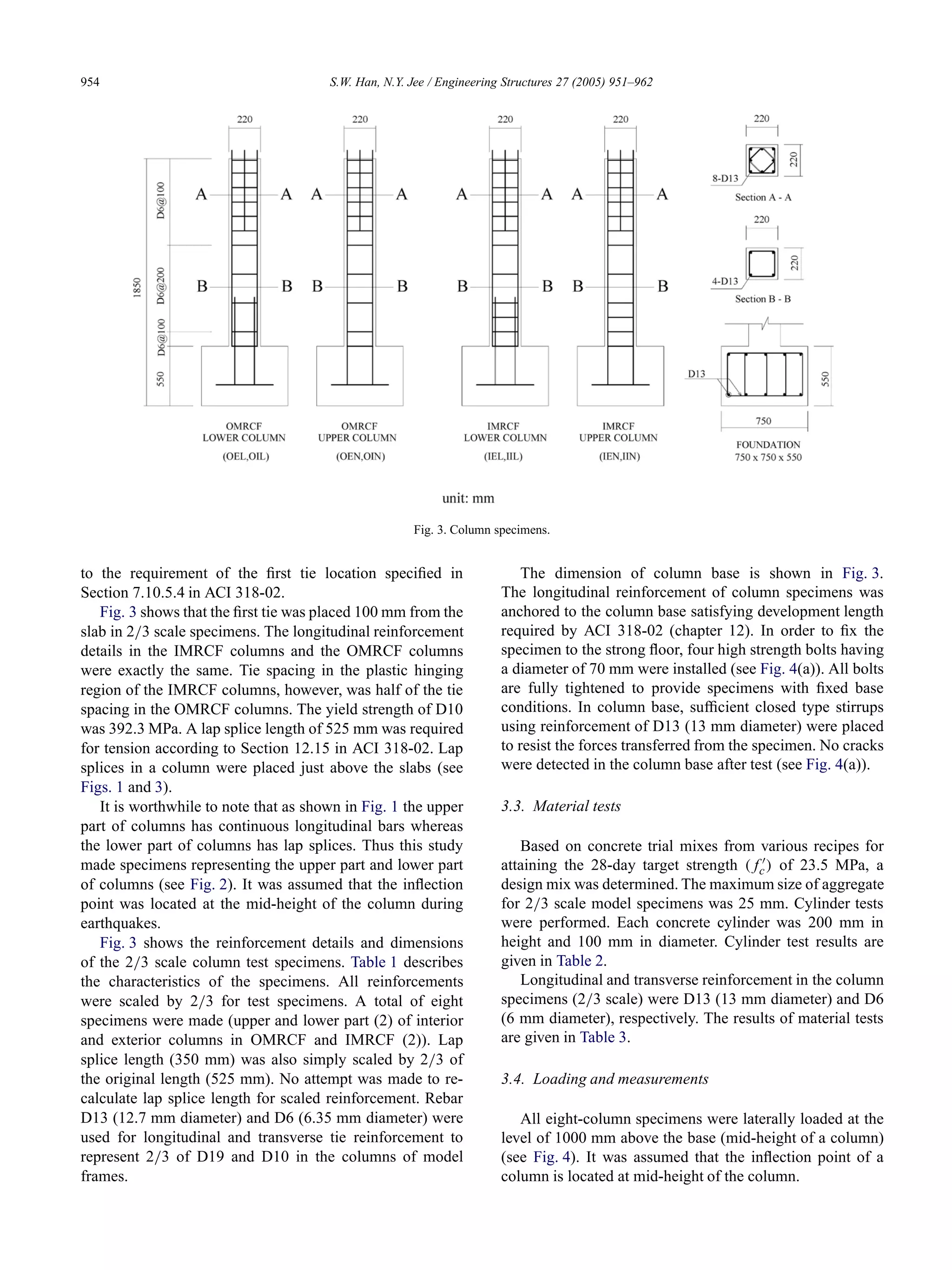
reinforcement in columns and beams (see Fig. 3). This
design was desirable for this study since this study attempted
to investigate the effect of different reinforcement details
of OMRCF and IMRCF columns on seismic behaviors of
those columns without interference of other factors such as
amount of longitudinal reinforcement and different member
sizes.
3.2. Column specimens
As shown in Fig. 2, only the columns in the first story
were evaluated since these columns should resist the largest
axial and lateral forces during an earthquake. The exterior
(a) Plan view.
(b) Elevation.
Fig. 2. Building layouts.
columns in the first story of the two model frames were
designed for an axial force of 644.3 kN and a bending
moment of 37 kN m, and the interior columns were designed
for an axial load of 1234.7 kN and a bending moment of
47.1 kN m. It is noted that those design forces contain load
factors.
All columns had a section of 330 mm × 330 mm
and contained four longitudinal reinforcements (D19
(19.1 mm diameter), fy = 392.3 MPa). Column
longitudinal reinforcement ratio (ρ) was 1.01%, which
slightly exceeded a minimum longitudinal reinforcing steel
of 1.0% (Section 10.9.1 in ACI 318-02).
Maximum shear force in the first story columns induced
by factored gravity loads was 31.4 kN. According to the
formula in Section 11.3.1.2 of the ACI 318-02, the concrete
shear strength of the first story columns (Vc) was calculated
as 73.5 kN. Minimum tie reinforcement (D10 with a
diameter of 9.53 mm) with spacing of 300 mm was placed
throughout the column in the OMRCF (Section 7.10.5.2
in ACI 318-02) and the first tie reinforcement was placed
150 mm from the slab or footing surface according](https://image.slidesharecdn.com/1-seismicbehaviorsofcolumnsinordinaryandintermediatemomentresistingconcreteframes-150516003342-lva1-app6891/75/1-seismic-behaviors-of-columns-in-ordinary-and-intermediate-moment-resisting-concrete-frames-3-2048.jpg)
![S.W. Han, N.Y. Jee / Engineering Structures 27 (2005) 951–962 955
Fig. 4. Test setting.
Table 1
Characteristics of the column specimens
Location Specimen name Loading plan Lap splice
OMRCF (IMRCF)
Interior
Lower part OIL (IIL)
Constant
column axial load
Upper part OIN (IIN)
(P = 0.28)
×
Exterior
Lower part OEL (IEL)
Varying
column axial load
Upper part OEN (IEN)
(P = 1.83V + 17.1)
×
O I L
(1): OMRCF (O), IMRCF (I) : having lap splices
(1) (2) (3)
(2): Interior (I), Exterior (E) ×: not having lap splices
(3): with lap splice (L), without lap splice (N)
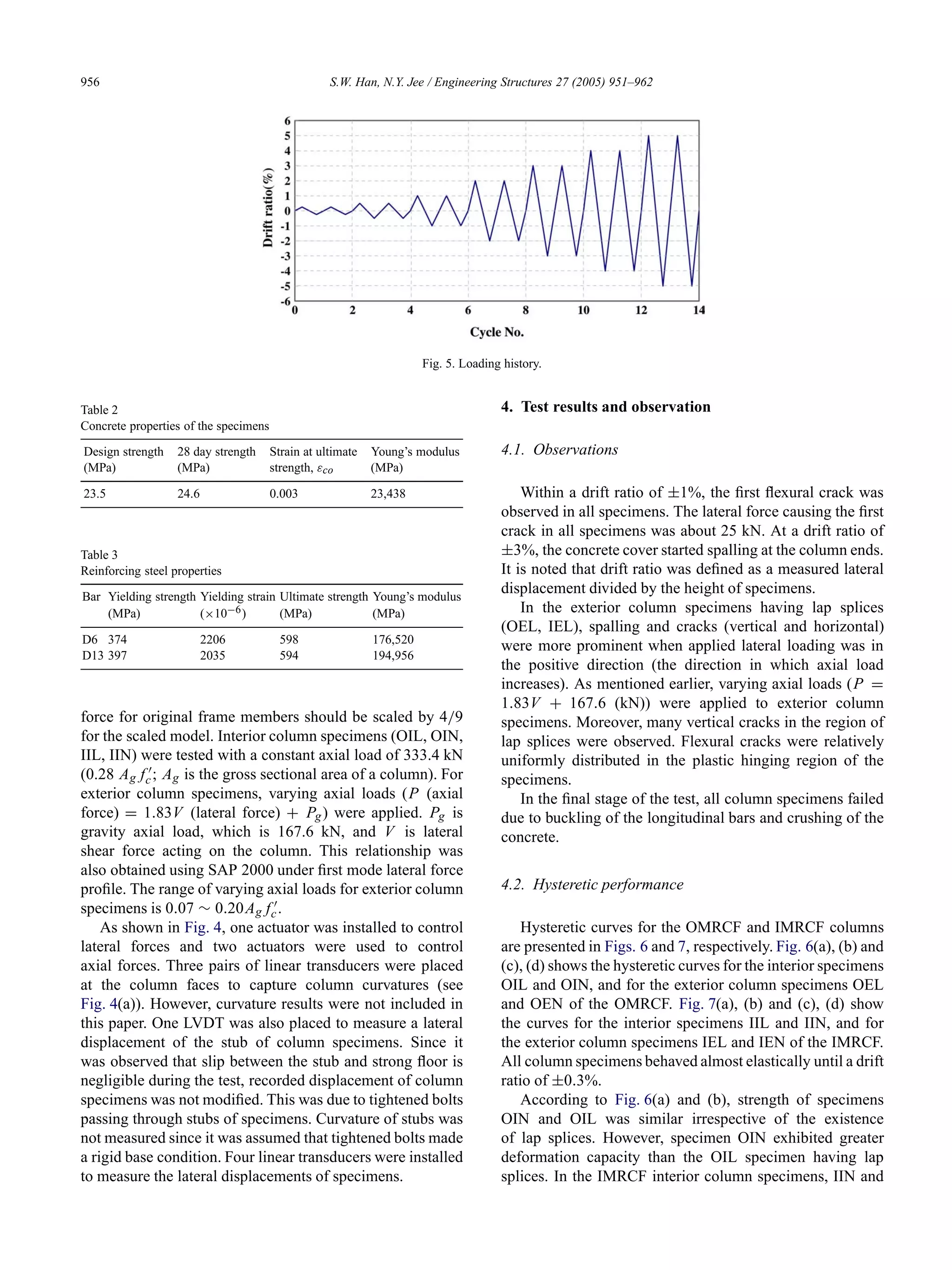
Quasi-static reversed cyclic loading (displacement con-
trolled) was applied. Two cycles were applied for each load-
ing amplitude. The loading history is shown in Fig. 5. Since
fluctuation of axial loads in the exterior columns was more
significant than in the interior columns, varying axial load-
ing was applied to the exterior column specimens, whereas a
constant axial load was applied to the interior column spec-
imens. Larger axial loads were applied to interior columns
due to a larger tributary area.
Axial loads were calculated by frame analysis using
SAP 2000 commercial software [5] without considering load
factors. Since specimens were scaled by 2/3, calculated](https://image.slidesharecdn.com/1-seismicbehaviorsofcolumnsinordinaryandintermediatemomentresistingconcreteframes-150516003342-lva1-app6891/75/1-seismic-behaviors-of-columns-in-ordinary-and-intermediate-moment-resisting-concrete-frames-5-2048.jpg)
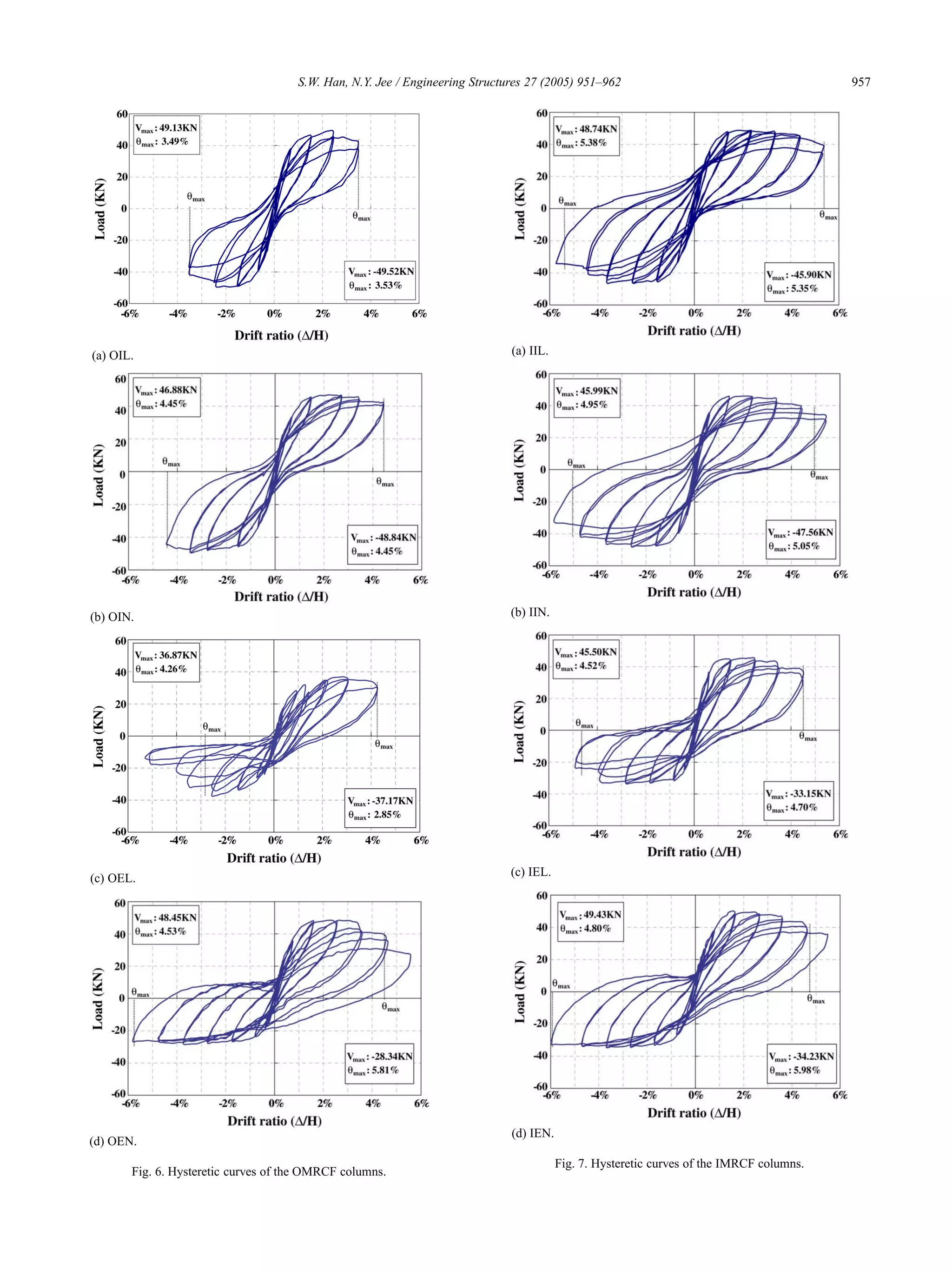
![962 S.W. Han, N.Y. Jee / Engineering Structures 27 (2005) 951–962
(5) In exterior column specimens of OMRCF and IMRCF,
hysteretic curves became narrower when they had lap
splices. However, the hysteretic curves of OMRCF
exterior columns are similar to those of corresponding
IMRCF exterior columns.
(6) According to the test results, the OMRCF and IMRCF
column specimens had drift capacities greater than
3.0% and 4.5%, respectively. Ductility capacity of those
specimens exceeded 3.01 and 4.53, respectively.
Acknowledgement
The support of Hanyang University is greatly acknowl-
edged.
References
[1] American Concrete Institute. Building code requirements for
reinforced concrete, ACI 318-95, 99, 02, Detroit, Michigan, 1995,
1999, 2002.
[2] Uniform Building Code (UBC). International conference on building
officials. 1997.
[3] Building Seismic Safety Council. NEHRP recommended provisions
for the development of seismic regulation for new buildings, Part 1
and 2, provisions and commentary, Washington, DC: FEMA; 1994,
1997.
[4] Portland Cement Association. Notes on ACI 318-99, 02 building code
requirements for structural concrete, Skokie, Illinois, 1999, 2002.
[5] Computers and Structures Inc. SAP2000, 1997.
[6] Han SW, Kwon OS, Lee L-H, Foutch DA. Seismic performance
evaluation of ordinary moment resisting concrete frames. SRS No.
633, Urbana, Illinois; 2002 November.
[7] Han SW, Kwon OS, Lee L-H. Evaluation of the seismic performance
of a three-story ordinary moment resisting concrete frame. Earthquake
engineering and structural dynamics, vol. 33. Wiely and Sons; 2004.
p. 669–85.
[8] BOCA, ICBO, SBCCI. International Building Code. 2000.
[9] Lee H-S, Woo S-W. Effect of masonry infills on seismic performance
of a 3-storey RC frame with non-seismic detailing. Earthquake
engineering and structural dynamics, vol. 31. Wiely and Sons; 2002.
p. 353–78.
[10] Aycardi LE, Mander JB, Reinhorn AM. Seismic resistance of
reinforced concrete frame structures designed only for gravity loads:
experimental performance of subassemblages. Structural Journal
American Concrete Institute 1994;91:552–63.
[11] Lynn A, Moehle J, Mahin SA, Holmes WT. Seismic evaluation
of existing RC building columns. Earthquake Spectra 1996;12(4):
715–39.
Sang Whan Han. Associate Professor, Dept. of Architectural Eng.,
Hanyang Univ., Seoul 133-791, Korea. Ph.D. (1994), University of Illinois
at Urbana-Champaign, Professional Engineer (US, Korea).
N.Y. Jee. Professor, Dept. of Architectural Eng., Hanyang Univ., Seoul 133-
791, Korea. Ph.D. (1992), Tokyo National University.](https://image.slidesharecdn.com/1-seismicbehaviorsofcolumnsinordinaryandintermediatemomentresistingconcreteframes-150516003342-lva1-app6891/75/1-seismic-behaviors-of-columns-in-ordinary-and-intermediate-moment-resisting-concrete-frames-12-2048.jpg)

The document summarizes a study that investigated the seismic behavior of columns in ordinary moment resisting concrete frames (OMRCF) and intermediate moment resisting concrete frames (IMRCF). Eight column specimens were tested under various loading conditions to evaluate factors like axial load type, existence of lap splices, and frame type. The test results showed that the column specimens had strengths and drift capacities greater than code requirements, though capacities varied depending on lap splices and transverse reinforcement spacing.


