Download to read offline
![International Research Journal of Engineering and Technology (IRJET) e-ISSN: 2395-0056
Volume: 09 Issue: 06 | Jun 2022 www.irjet.net p-ISSN: 2395-0072
© 2022, IRJET | Impact Factor value: 7.529 | ISO 9001:2008 Certified Journal | Page 1393
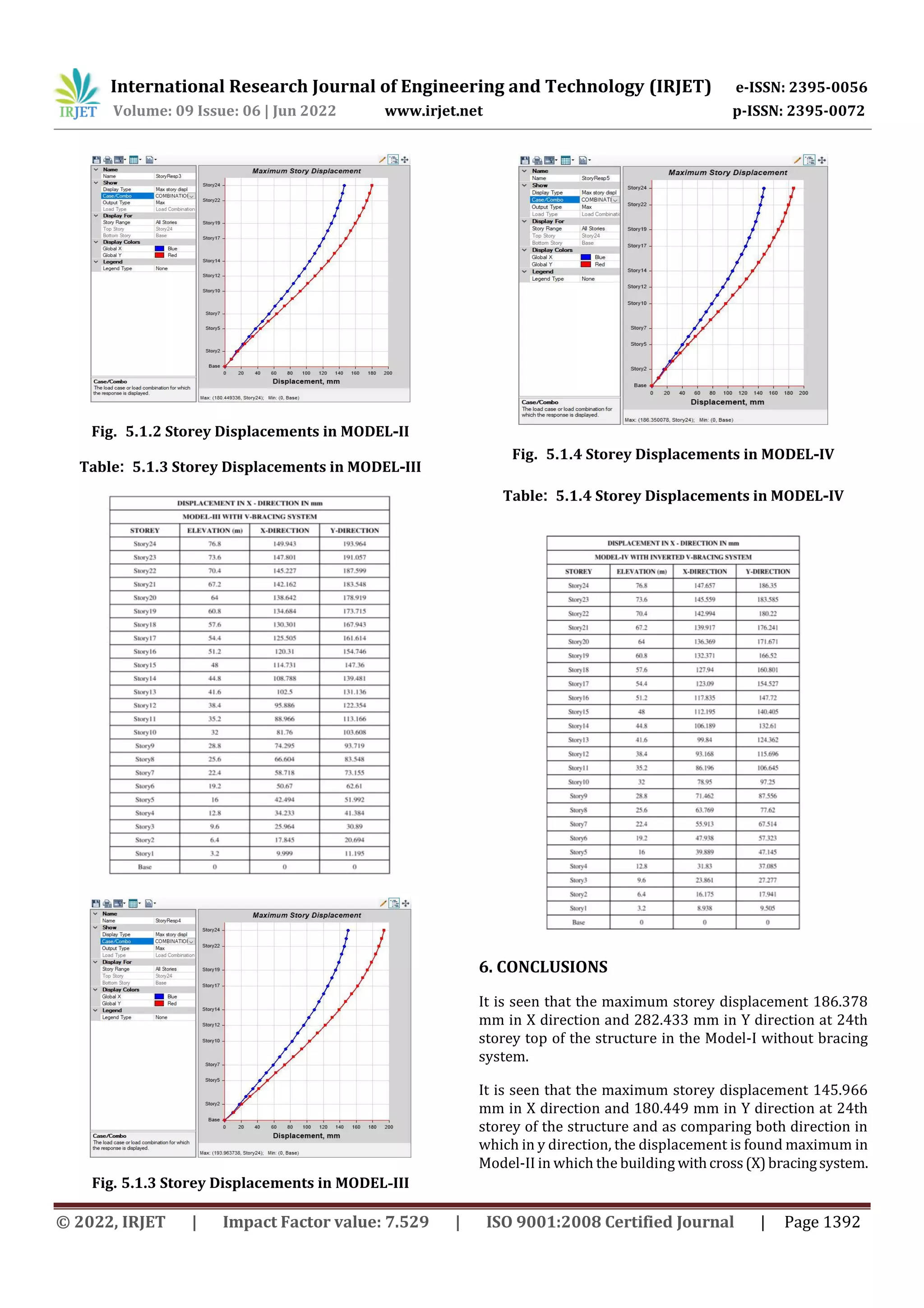
It is found that the maximum storey displacement 149.943
mm in X direction and 193.964 mm in Y direction at top of
the structure in Model-III with V bracing system.
It is seen that the maximum storey displacement 147.657
mm in X direction and 186.350 mm in Y direction at top of
the structure in model-IV with inverted V bracing system.
REFERENCES
[1] Viswanath K.G, Prakash K.B., Anant Desai, “Seismic
Analysis of Steel Braced Reinforced Concrete Frames”
International Journal ofCivil andStructural Engineering,
Volume 1, No 1, 2010
[2] Venkatesh S.V., H. Sharada Bai., Divya S.P., “Response of
a 3-Dimensional 2 X 3 Bays Ten Storey RC Frame with
Steel Bracings as Lateral Load Resisting Systems
Subjected To Seismic Load” International Journal of
Scientific & Engineering Research Volume 4, Issue 5,
May-2013.
[3] Yogendra Singh, “Lateral Load Resisting Systems for
MultiStorey Buildings” 4] M.D. Kevadkar, P.B. Kodag,
“Lateral Load Analysis of R.C.C Building”, International
Journal of Modern Engineering Research (IJMER),Vol.3,
Issue.3, May-June. 2013
[4] Dr. Vinod Hosur, “Earthquake-Resistant Design of
Building Structures”, Wiley India Pvt. Ltd, New Delhi,
India.
[5] S.K.Duggal, “Earthquake ResistantDesignofStructures”,
Oxford University Press.
[6] IS 1893 (Part 1): 2002, “Criteria for Earthquake
Resistant Design of Structures”, Bureau of Indian
Standards, New Delhi.](https://image.slidesharecdn.com/irjet-v9i6245-221013064507-947ffb8b/75/Analysis-of-Seismic-Behaviors-of-RC-Frame-Structure-With-Bracing-System-and-Without-Bracing-System-5-2048.jpg)

This document analyzes the seismic behavior of reinforced concrete frame structures with and without steel bracing systems. A G+23 square building is modeled in Etabs with beam and column dimensions of 300mm x 400mm and 300mm x 500mm respectively. The building is analyzed using response spectrum analysis as per Indian codes for different bracing configurations including no bracing, X bracing, V bracing, inverted V bracing, and eccentric bracing. Results show that maximum storey displacements are lowest for structures with inverted V and V bracing systems, followed by X bracing. The non-braced structure experiences the highest displacements, confirming that bracing systems effectively reduce seismic responses of RC frames.