Downloaded 15 times

![SINGLE CELL BRACED AT A TIME
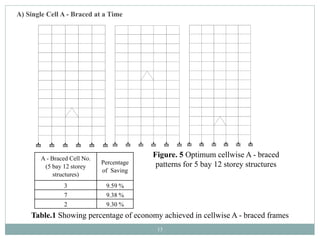
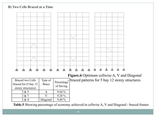
Initially it is tried with single cells braced at a time and later on few
cases tried with two cells and three cells braced at a time in order to
check economy to be procured with lesser or more braces.
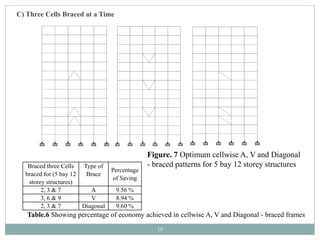
It is wise to localize our view over such cellwise braced frames which
offers more economy.
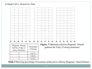
It is seen that A braced frames offer more economy as compared to V
and Diagonal braced frames which is 9.59 %.
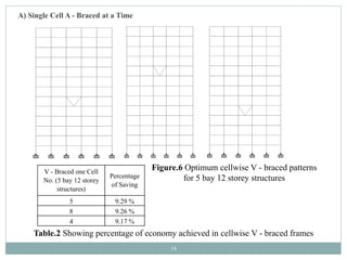
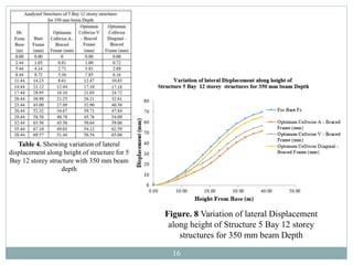
It is also seen that as the bracing location moves away from the base
ultimately the economy is getting reduced nominally owing to the
lateral displacements.
The lateral displacements are found to be more in case of cells braced
away from the base of the structure but within prescribed limits [12].
17](https://image.slidesharecdn.com/presentationcellwisebracedframes150317-170404130522/85/Presentation_on_Cellwise_Braced_frames-17-320.jpg)


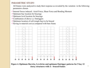
This presentation discusses the seismic response of cellwise concentrically braced frames. It introduces cellwise braced frames as a structural system that provides lateral stability through bracing elements arranged in cells within each bay. The document describes a study that analyzed 5 bay, 12 story reinforced concrete frames with different bracing configurations, including single-cell, two-cell, and three-cell arrangements. The study found that single-cell A-braced frames provided the highest material cost savings of up to 9.59% compared to bare frames. Two-cell and three-cell configurations further improved cost savings but required additional bracing. Overall, the study shows that optimally arranged cellwise braced frames produce a stiff, strong and econom