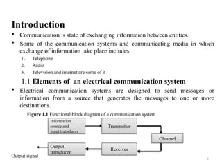
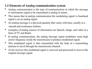
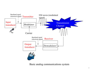
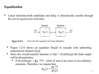
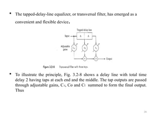
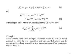
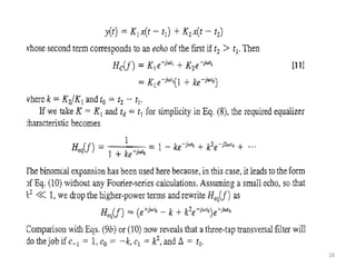
The document provides an introduction to communication systems, detailing the essential elements such as sources, transmitters, channels, and receivers, as well as differentiating between broadcasting and point-to-point communications. It covers analog communication systems, discussing the modulation of analog signals and the nature of information-bearing signals. Additionally, it delves into frequency domain analysis, signal distortion types, and companding techniques to mitigate distortion during transmission.
![29
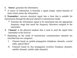
2. Nonlinear Distortion and Companding
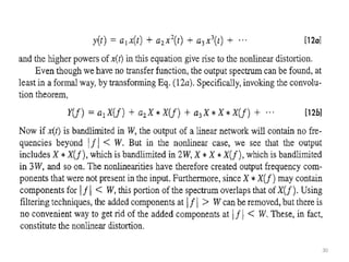
sine wave components of the signal are bent (sharply curved or an angle )
that the distortion is called nonlinear distortion.
The instantaneous values of input and output are related by a curve or
function y(t) = T[x(t)], commonly called the transfer characteristic.](https://image.slidesharecdn.com/introductiontocommunicationsystemchapter1-240825132328-03ea57d5/85/Introduction-to-communication-system-chapter-1-pptx-29-320.jpg)
![31
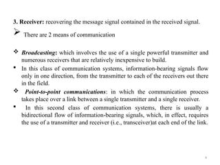
Companding
The joint use of compressing and expanding is called companding.
High amplitude analog signals are compressed prior to transmission and
then expanded in the receiver.
A compressor has greater amplification at low signal levels than at high
signal levels, similar to Fig. 3.2-9, and thereby compresses the range of the
input signal. If the compressed signal falls within the linear range of the
channel, the signal at the channel output is proportional to Tcomp[x(t)]
which is distorted by the compressor but not the channel. Ideally, then, the
expander has a characteristic that perfectly complements the compressor so
the expanded output is proportional to Texp{Tcomp[x(t)]} = x(t), as
desired.](https://image.slidesharecdn.com/introductiontocommunicationsystemchapter1-240825132328-03ea57d5/85/Introduction-to-communication-system-chapter-1-pptx-31-320.jpg)