This document summarizes the implementation of a digital current sharing controller for multiple power modules using a PIC16F876A microcontroller. The digital controller provides accurate current sharing of less than 1% error using a software-based automatic master-slave architecture. It offers advantages over analog controllers like easy implementation of complex algorithms, soft-starting, and fault protection through software updates instead of hardware changes. An experimental setup evaluated the digital controller alongside an analog UCC29002 controller, demonstrating balanced current sharing between two DC-DC converter modules.
These slides presents an overall discussion on fault location techniques generally used in present power transmission and distribution system. Later of the class we will discuss about the implementation principles and mathematical formulations.
DETECTING POWER GRID SYNCHRONISATION FAILURE ON SENSING BAD VOLTAGE OR FREQUENCYPradeep Avanigadda
This paper presents the development of a microcontroller based islanding detection for grid connected inverter with very simple under/over voltage and under/over frequency islanding detection algorithms.
The microcontroller monitors the under/over voltage and under/over frequency from utility grid and the processed value of voltage and frequency for turning ON/OFF the relay between a grid connected inverter and the utility grid.
The project would alternatively use a variable frequency generator using 555timer for changing the frequency while a standard variac shall be used to vary the input voltage for achieving the test conditions as stated above.
The Arab Gulf Cooperation Council (GCC) countries namely the United Arab Emirates, Bahrain,
Saudi Arabia, Oman, Qatar, and Kuwait have embraced changes to their power sectors with more
private sectors participation as a result of increasing demands for power due to rapid population,
commercial and industrial growth in their respective countries. Realizing the need for more reliable
GCC power grids with power exchange possibilities, the Governments of the GCC countries have
established the GCC Interconnection Authority to construct and operate a 400 kV interconnection
backbone grid between the six Member States (MS).
The GCC Interconnection network phase 1 was completed and successfully commissioned during the
first quarter of the year 2009. Phase 1 network consists of seven 400 kV substations interconnecting
the independent Member States’ Power Systems (MSPS): Kuwait, Saudi Arabia, Bahrain and Qatar
through a 900 km 400 kV overhead lines and a 51 km 400 KV submarine and land cables. This GCC
Interconnection phase I combines long distance high voltage overhead lines, high voltage cables and a
HVDC back-to-back substation. The HVDC connects the 50 Hz interconnected networks of the power
systems in Kuwait, Bahrain, Qatar, UAE and Oman with the 60 Hz system in Saudi Arabia.
The GCC Interconnection network phase 3 successfully completed when UAE 400 kV network was
connected to the GCC Interconnection network Phase 1 through double circuits 400 kV overhead
lines, and synchronised for the first time with Phase I network on April 2011 and Oman grid was
connected to UAE grid through double circuits 220 kV overhead lines on October 2011.
In order to prepare for the safe, secure and stable operation of the combined GCC interconnection
including UAE and Oman, a number of detailed operational studies were performed including system
studies, electromagnetic transients, protection studies, frequency control studies, and more. The paper
presents the results of these operational studies and the approach the operations issues arising from the
results of the studies were addressed
SRF THEORY BASED STATCOM FOR COMPENSATION OF REACTIVE POWER AND HARMONICSIAEME Publication
The power electronic devices like converters and inverters inject harmonic currents into AC
system due to their non linear characteristics. These devices draw high amount of reactive power
from source. The commencement of Nonlinear Load into the ac power system will have the effect of
harmonics. The presence of harmonics in system it will effected with power quality problems. Due
to this high amount of power losses and disoperation of power electronics devices is caused, along
with this Harmonics have a number of undesirable effects like Voltage disturbances. These
harmonics are needed to mitigate for Power Quality Enhancement in distributed system. Here the
device called STATCOM is one of the FACTS Devices which can be used to mitigate the harmonics
and reactive power compensation. The voltage source converter is core of the STATCOM and the
hysteresis current control is indirect method of controlling of VSC. In this paper we implement with
SRF based STATCOM control. SRF theory is implemented for the generation of controlling
reference current signals for controller of STATCOM. The Matlab\Simulink based model is
developed and simulation results are showed for linear and nonlinear load conditions.
A brief report on internship at PGCIL Hassan. This gives a brief information reguarding equipments which are used in a power grid. Classified information.
Automatic load sharing of transformer using microcontrollerPrakhar Anand
1. ABSTRACT:-
The transformer is a static device, which converts power from one level to another level.
The main aim is to protect the transformer under overload condition by load sharing.
Due to overload on transformer, the efficiency drops and windings get overheated and may get burnt.
Thus by sharing load on transformer, the transformer is protected. This will be done by connecting another transformer in parallel through a micro-controller.
The micro controller compares the load on the first transformer with a reference value. When the load exceeds the reference value, the second transformer will share the extra load.
Therefore, the two transformer work efficiently and damage is prevented. Main modules used here are sensing unit, control unit and micro-control.
A GSM modem is also used to inform the control station about switching.
The advantages of the project are transformer protection, uninterrupted power supply, and short circuit protection.
2. OBJECTIVE:-
To design & fabrication of a hardware which will monitor the performance of the load sharing process by taking power consumed by the load into consideration.
3. INTRODUCTION:-
Transformer is the vital component in the electric power transmission and distribution system.
The problems of overloading, voltage variation and heating effects are very common. It takes a lot of time for its repair and also involves lot of expenditure.
This work is all about protecting the transformer under overload condition. Due to overload the efficiency drops and the secondary winding gets overheated or it may be burnt.
So, by reducing the extra load, the transformer can be protected. This can be done by operating another transformer in parallel with main transformer through microcontroller and change over relay.
The microcontroller compares the load on the first transformer with a reference value. When the load exceeds the reference value, the slave transformer will automatically be connected in parallel with first transformer and share the extra load.
Therefore, a number of transformers work efficiently under overload condition and the damage can be prevented.
In this work, the slave transformers share the load of master transformer in the case of over load and over temperature conditions.
A sensor circuit containing microcontroller, current transformer etc. is designed to log the data from master transformer and if it is found to be in overload condition, immediately the slave transformer will be connected in the parallel to the master transformer and the load is shared.
Detecting Power Grid Synchronization Failure on Sensing Frequency or Voltage ...Edgefxkits & Solutions
Synchronization means the minimization of difference in voltage, frequency and phase angle between the corresponding phases of the generator output and grid supply. An alternating current generator must be synchronized with the grid prior to connection. It can’t deliver the power unless it is running at same frequency as the network.
Project Report on “WORKING MODEL OF POWER GRID/SMART GRIDPrasant Kumar
Over a century of years ago, the power system has been developed into one of the predominantly complicated network viewed in human history. Due to the mounting of consumption demand, the modern electrical power grids are now increasing into a huge structure with various interconnected regional grids, owned and operated by Power Corporation at every height and hierarchy.
Due to dense attention, management and operation among various power companies periodically complex the cross-region transmission work and more time results in poor coordination and inefficient power delivery. So the conventional power grid in today’s world is facing some upcoming challenges.
As the demand and category of consumption increases, various types of modern technologies are introduced in power system, like the electric component charging system, distributed renewable energy generation, smart meters etc, that all work towards the complication of modern power delivery.
The day to day increasing dependence on electricity and growing need for power quality have been regularly asking for better power delivery, faster power restoration and more flexible pricing among others.
An electrical grid is an interconnected network for delivering electricity from suppliers to consumers. It consists of three main components power generation transmission and distribution.
Meet this week’s trio, Helen, Felix and Girl! Helen is a mostly blind and completely deaf dapple mix. Her parents were ill-equipped to give Helen the care that she needed, and she became an owner surrender. Felix is a small, long haired Dachshund. Felix had once been physically abused, including being thrown against a wall. Daisy (Girl), is a wire-haired dachshund mix, with a very sweet personality. She caught the eye of her foster mom in the shelter kennel, right next to Felix. Felix, Girl and Helen are now waiting for their forever homes at Denver Dachshunds Rescue in Colorado.
Dogs can be strangers to each other just like people.
Meet Zephyr and Sabre! A few weeks ago, these two had no idea about each other. They were brought to Orange County Animal Control in Orange, California. Zephyr and Sabre were terrified while they were living in the shelter. As each day passed, they were shaking in fear, terrified for their lives.
During her 20-year career in finance and insurance, Dawn Johnson of San Antonio, Texas, supported a variety of community programs. Following her career at USAA, Dawn Johnson continues to be an avid philanthropist supporting the Leukemia and Lymphoma Society.
Suggested Readings for Children and Teenssuzi smith
Preschool/Elementary
Brown, Laurie and Marc. When Dinasours Die. Little, Brown Books for Young Readers. April 1988. Simple language, explains feelings people may have regarding the death of someone they love, discusses ways to honor the memory of someone who dies.
Burleigh, Robert. Goodbye Sheepie. Marshall Cavendish Corp. Tarrytown, NY 2010. A dad helps his son deal with the death of his pet dog.
Buscaglia, Leo. The Fall of Freddie the Leaf. Charles B. Slack Co. 1982. Uses the life of a leaf to talk about death as part of the life cycle.
Fitzgerald, Helen. The Grieving Child. A Parents Guide. Simon and Schuster, NY. 1992. A guide for parents seeking to explain death to a child. Suggestions given to deal with emotional responses and helping a child’s adjustment to a new life.
Hazen, Barbara Shook. Why Did Grandpa Die? A Book about Death. Golden Book, NY 1985. Death and loss in a family setting, Deals with the suddenness of death and a girl’s anger, covers stages and the process of grieving.
How Advanced Simulation will Impact the Offshore Industry both Now and in the...Altair
The easy days of Oil and gas extraction is over, and the ability to extract Oil and Gas from harsh enviornments is very dependent on the ability to overcome technical challenges through the use of advanced numerical analysis and simulation. Technical challalenges currently faced in the industry include High Pressure High Temperature (HPHT), Utra Deep Water (UDW) with water depths greater than 10,000 ft, and the Arctic with potentially 20% untapped hydro carbon reserves. These technical challenges are overcome through more use of advanced analysis and simulation, and this allows cost effective solutions to be obtained.
Also the Industry is currently being challenged by a low oil price, and lots of companies are forced to look at cost and schedule. This as a result, allows the opportunity for the use of advanced analysis to help solve Engineering challanges in an efficient manner and save potentially millions of dollars in the Engineering. The ways that this is undertaken is presented and discussed.
There are different types of Analysis simulation used in the Offshore Industry, for example FEA, CFD, Coupled Analysis etc. Also computer power is ever increasing in compuational efficiencies, and novel methods, such as the use of Cloud computing, has had a big impact on the way that analysis is undertaken. These different methods of software and hardware are discussed in relation to the Offshore Industry, and an indication is given in to how these methods will affect the Industry in the future.
International Journal of Engineering Research and DevelopmentIJERD Editor
Electrical, Electronics and Computer Engineering,
Information Engineering and Technology,
Mechanical, Industrial and Manufacturing Engineering,
Automation and Mechatronics Engineering,
Material and Chemical Engineering,
Civil and Architecture Engineering,
Biotechnology and Bio Engineering,
Environmental Engineering,
Petroleum and Mining Engineering,
Marine and Agriculture engineering,
Aerospace Engineering.
This project is used to control electrical appliances or loads through a personal computer (PC) like theatre lighting can be centrally controlled from a PC.
International Journal of Engineering Research and Applications (IJERA) is an open access online peer reviewed international journal that publishes research and review articles in the fields of Computer Science, Neural Networks, Electrical Engineering, Software Engineering, Information Technology, Mechanical Engineering, Chemical Engineering, Plastic Engineering, Food Technology, Textile Engineering, Nano Technology & science, Power Electronics, Electronics & Communication Engineering, Computational mathematics, Image processing, Civil Engineering, Structural Engineering, Environmental Engineering, VLSI Testing & Low Power VLSI Design etc.
Efficient bridgeless SEPIC converter fed PMBLDC motor using artificial neural...IJECEIAES
In this paper, a new design of Bridgeless SEPIC (Single Ended Primary Inductance converter) with Artificial neural network (ANN) fed PMBLDC Motor drive is proposed to improve Power Factor. The proposed converter has single switching device of MOSFET, so the switching losses is reduced.ANN is used to achieve the higher power factor and fixed dc link voltage. Also the ANN methodology the time taken for computation is less since there is no mathematical model. The output voltage depends on the switching frequency of the MOSFET. The BLSEPIC act as a buck operation in continuous conduction mode. Detailed converter analysis, equivalent circuit and closed-loop analysis are presented for 36V, 120W, 1500rpm BLDC Motor drive. This proposed converter produces low conduction loss, low total harmonic reduction, low settling time and high power factor reaching near-unity. All the simulation work is verified with MATLAB – Simulink.
This paper describes digital pulse width modulation (DPWM) controller technique for implementing low-power buck converters. The converter is operated at Discontinuous conduction mode to reduce the losses during switching. A DPWM controller is developed to achieve the best possible transient performance under load current change. Simulation of the converter is carried out using MATLAB/SIMULINK and the results indicate that it has good dynamic performance under load change.
Design and Simulation of Efficient DC-DC Converter Topology for a Solar PV Mo...Sajin Ismail
Modulated Integrated Converter systems are considered to be the new and global turning point in the field of
Solar PV systems. These converters are highly recognised for its modular size and compact nature and they are supposed to
be attached directly with each PV module and since one PV module is having the power rating of a few watts ranging from
0-500Ws, the design rating would be in the same range and thus the most vital condition in such a design is efficiency
under these relatively low loads. In this paper an isolated interleaved boost converter topology is considered in the DC-DC
section and which is designed and simulated for a specific power rating (250W) and the efficiency is analysed with varying
load conditions and compared with the target efficiency of the system.
Wireless monitoring and control for smart grid and home appliancesUmayal Saravana Selvan
Secure and efficient communication between human being and managed devices are critical for smart grid and smart home. The power monitoring and controlling is playing a significant role in this project. In this project we proposes a new idea. The power consumption and their tariff amount will be automatically shown in the LCD display. This information will be automatically received to electricity board by using the Zigbee modem. From home we will pay the amount by using smart card system. If the amount is not paid within
the dead time the proposed system will automatically trip power supply from the EB station itself. When the amount is paid electricity board will enable the power supply again automatically.
Design and simulation of Arduino Nano controlled DC-DC converters for low and...IJECEIAES
This paper mainly focuses on the controller of portable direct current to direct current (DC-DC) converter which may be simple, low cost and efficient. Nowadays, proportional integral (PI) controller and opto-isolator based circuits are used for switching control. The switching control through the controller makes the DC-DC converter into larger circuit and less efficient. This problem will be rectified using the Arduino Nano controller which is small and low cost-effective controller. It is useful for low and medium power applications like residential solar power system, electronic gadgets, and academic laboratories. Arduino Nano-based DC chopper has been developed, and the Proteus software used for simulation. The different topologies of DC choppers like buck, boost, and buck-boost converter have been designed with mathematical calculations and simulated.
Design consideration of an mmc hvdc system based on 4500 v:4000a emitter turn...Ghazal Falahi
Excessive power loss is a major concern in high voltage and high power applications and is considered one of the main drawbacks of VSC-HVDC system when compared with traditional HVDC system based on thyristor technology. This is primarily caused by high switching loss associated with switching devices used in the VSC-HVDC. This issue can be largely addressed by using the emerging MMC-HVDC topology, which requires much lower switching frequency than traditional VSC-HVDC. Emitter turn-off thyristor (ETO) is one of the best high power switching devices packed with many advanced features. ETO thyristor based MMC-HVDC system is therefore an extremely attractive choice for ultra-high voltage and high power HVDCs. This paper discusses the operation principle of ETO based MMC-HVDC as well as its design and loss comparison with other solutions.
IRJET- Design and Implementation of Solar Charge Controller
Digital Implementation of Paralleling DC_DC conv
1. DA148 1
Abstract— This paper describes implementation of
digitally controlled current sharing in multiple power modules to
be used in high current requirement applications. This leads to
better system performance and system cost reduction.
The Digital Load share controller is developed using low cost
PIC16F876A µC with appropriate analog interface. The
performance of the Digital Load share controller is presented in
this paper along with Analog Load share controller UCC29002.
Index Terms— Analog Load Share Controller, Digital Load share
controller, Isolated buck DC-DC converter, paralleled power
modules.
I. INTRODUCTION
wide range of mission critical applications such as
Satellites, telecommunication, servers, etc., requires
either or both (n+1) redundancy and high load current
requirement. In order to satisfy the above needs we need to
provide Multiple Paralleled Power modules. But whenever the
converter modules are in parallel, one power module will take
the full load and the other module becomes idle. In order to
overcome this problem the only solution is current sharing
among the parallel power modules.
The current sharing equalizes the load current and thermal
stresses among paralleled power modules which lead to
improvement in overall system performance. The current
sharing also provides an improvement in terms of electrical
component reliability; for example, Mean Time between
Failure (MTBF) roughly doubles with every 10°C decrease in
operating temperature. Enforcing proper load sharing can also
result in using power supplies with lower nominal ratings
because of the reduced current in each. This technique, in turn,
can translate into an overall lower system cost.
There are several typical Current sharing methods, such as -
Automatic Master/ Slave Architecture
Droop Architecture
Democratic Architecture
Current mode control
Master/ slave Architecture
Dhananjay P, M.TECH – Power Electronics, 4th Semester, The Oxford
College of Engineering, Bangalore, dhananjay474@gmail.com, Phone no:
9480011359.
Jayakumar, M.TECH, Assistant Professor, EEE Dept, The Oxford College
of Engineering, Bangalore, njktry@yahoo.co.in.
Among various methods specified Automatic Master/
Slave architecture is more efficient and hence implemented in
this work.
II. WORKING OF PIC16F876A BASED DIGITAL LOAD SHARE
CONTROLLER:
The basic working of Digital Load share control card is
based on Automatic master/ slave architecture. Where the
power module carrying highest current will be the master and
the remaining modules becomes the slave. The slave power
module adjusts its regulated output voltage in terms of mV
according to command received from master module until
balanced current sharing occurs.
The Fig 2.1 shows the block diagram of two paralleled
24V/15A DC-DC converter along with two PIC16F876A µC
based Digital Load share controller connected at the load side.
For reasons of simplicity, only two converters are paralleled in
this work. The functional blocks of PIC16F876A µC based
Digital load share control
Fig 2.1 Digital load share control card connected to
multiple 24V/15A DC – DC converters
card is shown in the Fig 2.2 and its working are as follows:
A. Current Sense resistor (Rsense):
The Current sense resistor connected in positive output
rail of the DC/DC converter is of value 2mΩ. Rsense resistor
provides a maximum of 30mV, as an input to the Differential
Current sense amplifier at full load of 15A. The advantage of
Rsense resistor is, power dissipation is very less of 0.45W at
full load.
Digital Implementation of Current Sharing in
Multiple Power Modules
A. Dhananjay P and B. Jayakumar
A
2. DA148 2
B. Differential Current Sense Amplifier:
Its used to measure voltage across current sense resistor
(Rsense) which will be in terms of mV. The gain of the
Differential currrent sense amplifier is 100. Hence, the output
of the differential amplifier will be,
Vcso = Gain × (Vin+ - Vin-) 2.1
The maximum output of current sense amplifier is 3V at full
load of 15A. The current sense amplifiers Noise roll off is
designed for 3.5Hz.
Fig 2.2 Functional Blocks of Digital Load Share
Control Card.
C. Load Share Unity Gain Amplifier:
It’s a unity gain buffer amplifier to provide isolation
between the Load share bus voltage and the output of Current
sense amplifier. The amplifiers feedback consists of diode
which is used to select the particular power module as ‘master’
and remaining modules as ‘slave’.
D. Buffer:
It’s a unity gain buffer, which is used to ensure that the
Load Share bus is not loaded by the internal impedance of the
Digital control card and to provide the Load Share bus voltage
to one of the analog pin of µC.
E. Load Share Bus:
The Load share bus is used to carry the Master modules
current sense voltage (Vcso) to the Buffer of the slave Power
modules digital control card.
F. Programmable Current Sink:
The output voltage of the R-C filter is used to adjust the
output voltage of the slave power module to balance the load
current. This is done by the adjust amplifier and its companion
NPN transistor. The adjust amplifier provides signal
conditioning for the error signal and its output drives an NPN
transistor which is configured as a programmable current sink.
A resistor from its emitter to ground and the error voltage
defines the current, IADJ, which flows through the ADJ pin of
the digital Load–share controller and the positive output
terminal. The IADJ current causes a voltage drop across the
resistor which requires the power supply to increase its output
voltage. The resulting higher power supply output voltage
increases the output current of that particular module until the
output current levels equal out among the units. At that point
load sharing has been established.
G. Algorithm:
The following operations have been performed in the program
for current sharing in multiple power modules.
1. The analog signal of the differential current sense
amplifier output and Load share bus voltage has been
converted to digital form using the inbuilt “Analog to digital
converter”
2. Comparison of the “Load share bus digital value” and
“Current sense amplifier digital value” is done. Here, the
Output may be…
(I) If “Load share bus digital value” is greater than the
“Current sense amplifier digital value” by 100mV, the µC
increments the error voltage from zero.
(II) If the “current sense amplifier digital value” becomes
greater than or equal to “Load share bus digital value” by
100mV, the adjust voltage stops incrementing and retains the
previous value. Hence during this condition balanced current
sharing is achieved.
(III)If the “Load share bus digital value” becomes less
than or equal to the “Current sense amplifier digital value” by
10mV then the error voltage starts decreasing and continues to
decrease until the above condition becomes false or error
voltage reaches to zero. This condition occurs during false
operation of the system i.e. when the load share bus shorts with
the ground or supply or when the other Power module Turn –
off.
In order to provide the stability to the digital controller
we have provided a “Hysteresis gap” of 90mV between the
increment and decrement conditions. After performing one of
the above three conditions, the samples of Current sense
amplifier output value and the Load share bus value are again
obtained and checked for any of the three conditions discussed
above.
The detailed working of the µC is shown in the fig
2.3.The averages of 16 samples of individual current sense
amplifier value and load share bus value are calculated
separately and further used for computation purposes. This is
to eliminate the effect of noise on the analog input or wrong
conversion.
In order to convert the Digital adjust voltage value to
DC form, we use the combination of PWM generator and RC
filter instead of DAC, mainly to reduce the system cost.
System configuration required in order to use the Digital
Load share control card is – “Power module should have
Remote sense capability or the Power module should have
adjust input or both”.
III. BRIEF REVIEW OF CONVENTIONAL ANALOG LOAD SHARE
CONTROLLER:
3. DA148 3
Among various available Analog Load share control IC’s
in market we have chosen UCC29002 IC made by Texas
instrument. The Analog control cards are designed using large
number of on-chip op-amp’s and transistors to establish
Automatic Master/Slave architecture as shown in Fig 3.1. Here
the UCC29002 is capable of current sharing with 1% current
share error. It is also capable of current sharing only for range
of output voltage 4.5V to 35V. The IC is capable of fault
analysis and protection i.e. when the load share bus is shorted
to ground or supply. The UCC29002 load share control IC
requires minimum external components as shown in fig 3.2.
IV. ADVANTAGES OF DIGITAL LOAD SHARE CONTROL CARD:
A complex control algorithm is difficult to implement with
analog hardware components but can be easily implemental
in firmware.
Soft starting, slope compensation, interleaving, and fault
protection can also be easily implemented without any
external components.
Modifying the control methodology for different field
applications requires only software revision, and does not
require hardware modification.
The fan out can be increased.
Accurate current sharing of less than 1% current share error
at full load may be achieved.
V. EXPERIMENTAL SETUP:
The specifications of the Isolated buck DC – DC converters
used in this prototype are shown in Table 5.1. The Digital load
share controller designed is evaluated by placing Digital
control card in one power module and the UCC29002 based
Analog control card in another power module as shown in the
Fig5.1. Before evaluating the performance of the Digital Load
share control card, we set one power module as the Master and
the other as the slave. In the Fig5.2 the power module on the
right side is the master, taking the full load and the power
module on the left side is the slave, taking no load. The master
module Output voltage is greater than the slave power module
by 0.1V. When the digital control card power supply of +12V,
±5V is made on, the current sharing take place and finally the
balanced current sharing is achieved as shown in Fig 5.3.
Fig2.3: Flow Chart of working of PIC16F876A in Digital Load Share control Card.
Since Load share bus voltage is greater than the current sense
amplifier output voltage in the slave module. The
microcontroller makes error voltage to increase in terms of
20mV. Hence there will be a voltage drop at the resistor
4. DA148 4
present at the emitter side of the programmable current sink
which makes the output voltage of the slave module to rise by
driving the current.
Fig 3.1: Functional Blocks of UCC29002 Analog Load share control IC
Fig 3.2: Typical UCC29002 Load share controller connection in between the
power supply and the common power bus.
Fig 5.1: Proposed Parallel DC – DC converter with Digital Load share control
card.
Table 5.1: Specifications of Isolated DC-DC converter.
The output current of the slave module increases until uniform
current sharing occurs in both the module. When the balanced
current sharing occurs the Load share bus amplifier output
voltage will be almost equal to current sense amplifier output
and under this condition output voltage on both the power
module will be of 24.2V.
Fig 5.2: The paralleled Power modules output Voltage and current display
before current sharing.
Fig 5.3: Balanced current sharing of two paralleled 24V/15A DC – DC
converters.
VI. EXPERIMENTAL RESULTS AND DISCUSSIONS:
The test results is taken for both PIC16F876A µC based and
UCC29002 based load share controller as shown in the table
6.1 and 6.2. The digital load share controller exhibits efficient
operation under wide power ranges and it’s capable of
generating 5V as an
Table 6.1: Test results of UCC29002 based Load share control of two
Paralleled DC-DC converter modules
Table 6.1: Test results of PIC16F876A µC based Load share control of two
Paralleled DC-DC converter modules.
Input to the programmable current sink and in this work the
maximum voltage input given to the programmable current
sink by µC is 2V. The analog load share controller UCC29002
is capable of generating only 3V as error voltage to
programmable current sink used in the IC. When the current
sense amplifier output voltage is greater than 5V we can just
place the potential divider at the input of the µC, hence it’s
capable for higher current application greater than 50A. The
Digital current share control card is capable of adjusting the
voltage of the slave module for large voltage difference
between the slave and master module of 0.5V accurately. But
5. DA148 5
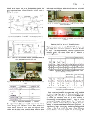
Analog current share controller UCC29002 is capable of
adjusting the voltage for small voltage difference of 0.2V
between the slave and master module.
VII. CONCLUSION:
From the above test results we can say that the low cost digital
load share control card can replace the analog load share
control card with accuracy in its current sharing and various
advantages of it compared to analog load share controller as
discussed earlier. The usage of these digital load share
controller as proven advantageous over some of the previous
Digital controller because of its parallel processing capability
and due to its hybrid quality; of using both digital and analog
components. By choosing Hybrid load share controller we
have reduced the burden on the µC and maintained sufficient
computational speed and performance without opting for High
end processors such as DSP.
VIII. ACKNOWLEDGMENT
The current work was carried out at M/S Chirra Electronics
Power labs Pvt Ltd, Bangalore. We wish to acknowledge their
support and guidance throughout the tenure of this work.
IX. REFERENCES
[1]T.S.Anandhit, S.P.Natarajan and T.Anitha, “UC3907 ASIC and
TMS320F2407A DSP based Control of Paralleled Buck DC-DC
Converters”, Indicon 2005 Conference, Chennai, India, 11- 13 Dec. 2005
[2] Siew-Chong Tan, Yuk-Ming Lai and Kevin Yan-Chun Wong, “An
Alternative configuration for Digitally controlled parallel connected DC-
DC Power Converters”, ECTI transactions on Electrical eng, electronics
and communications vol.4, no.1 February 2006
[3]Texas Instrument, “UCC29002 Load Share Controller” , 2007
[4] GUO Guoyong and SHI Bingxue, “Design of multi-phase dc-dc converter
with master-slave current sharing control”, IEEE, 2002.