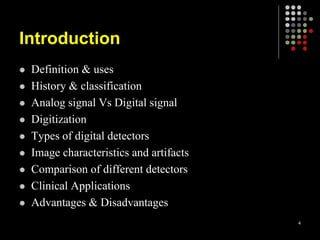
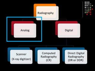
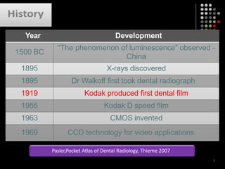
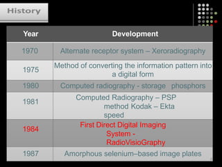
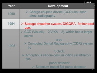
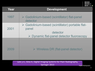
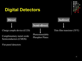
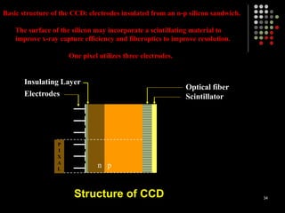
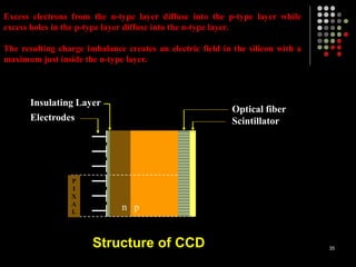
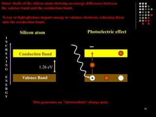
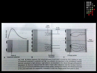
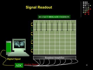
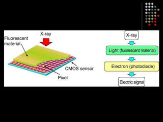
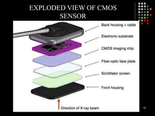
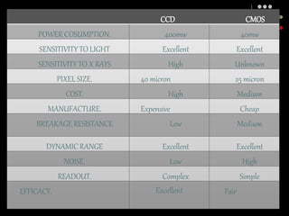
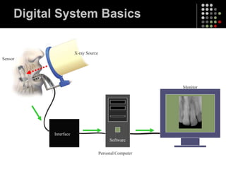
Digital IMAGING IN
DENTISTRY
1
A PICTURE IS WORTH A
THOUSAND WORDS
2
3
Introduction
 Definition & uses
 History & classification
 Analog signal Vs Digital signal
 Digitization
 Types of digital detectors
 Image characteristics and artifacts
 Comparison of different detectors
 Clinical Applications
 Advantages & Disadvantages
4
Radiography
Digital Radiography
Analog Digital
Scanner
(X-ray digitizer)
Computed
Radiography
(CR)
Direct Digital
Radiography
(DR or DDR)
5
HISTORy
6
Year Development
1500 BC
“The phenomenon of luminescence” observed -
China
1895 X-rays discovered
1895 Dr Walkoff first took dental radiograph
1919 Kodak produced first dental film
1955 Kodak D speed film
1963 CMOS invented
1969 CCD technology for video applications
Pasler,Pocket Atlas of Dental Radiology, Thieme 2007
7
Year Development
1970 Alternate receptor system – Xeroradiography
1975
Method of converting the information pattern into
a digital form
1980 Computed radiography - storage phosphors
1981
Computed Radiography – PSP
method Kodak – Ekta
speed
1984
First Direct Digital Imaging
System -
RadioVisioGraphy
1987 Amorphous selenium–based image plates
8
Year Development
1990
 Charge-coupled device (CCD) slot-scan
direct radiography
1994  Storage phosphor system, DIGORA for intraoral
use.
1995
 CCD (Visualix – 2/VIXA – 2), which had a larger
active
area
 Computed Dental Radiography (CDR) system
by
Schick.
 Amorphous silicon–cesium iodide (scintillator)
flat-
panel detector
 Selenium-based flat-panel detector
9
Year Development
1997  Gadolinium-based (scintillator) flat-panel
detector
2001
 Gadolinium-based (scintillator) portable flat-
panel
detector
 Dynamic flat-panel detector fluoroscopy
2009  Wireless DR (flat-panel detector)
Lanc¸a L, Silva A, Digital Imaging Systems for Plain Radiography,
Springer 2013 Digital Radiography
10
11
Francis Mouyen invented the
first intra-oral digital detector
Definition
 It is a method of capturing image using a
sensor, breaking it into electronic pixels,
presenting and storing the image using a
computer.
12
DIGITAL IMAGING
 Digital imaging are acquired either
 DIRECTLY – using a sensor or imaging plate
replacing conventional film
 INDIRECTLY – by scanning and digitizing a film-
captured image.
 Direct digital imaging systems are divided into
two types :
- Real time or CORDED
- Photostimulable phophor storage
plate or CORDLESS 13
Classification
Direct
Indirect
The image is acquired in a digital format
CCD, CMOS.
Analog image is digitized
e.g. scanning of radiographs /
photograph of a radiograph
Semi-direct Involves 2 steps in film acquisition.
Photostimulable phosphor plates (PSP)
14
ANALOG vs DIGITAL
What is Analog?
&
What is Digital?
15
16
HOW THE DETECTOR CREATES AN IMAGE
The Original Image
1
1
1
1
1
1
1
1
1
1
1
1
1
1
1
1
1
1
1
1
1
1
1
1
1
1
1
1
1
1
1
1
1
1
1
1
1
1
2
2
2
2
1
1
1
1
1
1
1
1
1
1
2
2
2
2
1
1
1
1
1
1
1
2
2
2
2
1
1
1
1
1
1
2
4
6
5
4
6
2
1
1
1
1
1
2
1
1
7
4
5
2
1
1
1
1
2
6
2
1
1
1
1
2
3
6
2
1
1
1
1
2
6
9
5
4
2
1
1
1
1
1
2
4
5
1
2
1
1
1
1
1
1
2
2
2
2
1
1
1
1
1
1
1
1
2
2
2
1
1
1
1
1
1
1
1
1
1
2
2
2
2
1
1
1
1
1
1
1
1
1
1
1
1
1
1
1
1
1
1
1
1
1
1
1
1
1
1
1
1
1
1
1
1
1
1
1
1
1
1
3
8
3
3
3
3
3
3
3
3 3
3
3
3
3
3
3
3
3
8
3
3
3
3
3 3 3
3
3 3
3
3
3
3
3
3
3
3
3
3
3
3
3 3
3 3 3 3
3 3 3 3
3
3
3
3 3
It converts that picture into a
number.
For purposes of this example we’ll
use the numbers from 1 to 9.
HOW THE DETECTOR CREATES AN IMAGE
1
1
1
1
1
1
1
1
1
1
1
1
1
1
1
1
1
1
1
1
1
1
1
1
1
1
1
1
1
1
1
1
1
1
1
1
1
1
2
2
2
2
1
1
1
1
1
1
1
1
1
1
2
2
2
2
1
1
1
1
1
1
1
2
2
2
2
1
1
1
1
1
1
2
4
6
5
4
6
2
1
1
1
1
1
2
1
7
4
5
2
1
1
1
1
2
6
2
1
1
1
1
2
3
6
2
1
1
1
1
2
6
9
5
4
2
1
1
1
1
1
2
4
5
1
2
1
1
1
1
1
1
2
2
2
2
1
1
1
1
1
1
1
1
2
2
2
1
1
1
1
1
1
1
1
1
1
2
2
2
2
1
1
1
1
1
1
1
1
1
1
1
1
1
1
1
1
1
1
1
1
1
1
1
1
1
1
1
1
1
1
1
1
1
1
1
1
1
1
3
8
3
3
3
3
3
3
3
3 3
3
3
3
3
3
3
3
3
8
3
3
3
3
3 3 3
3
3 3
3
3
3
3
3
3
3
3
3
3
3
3
3 3
3 3 3 3
3 3 3 3
3
3
3
3 3
Here is the pixel value
map without the
original image.
Each of the pixel
values is then sent to
the computer.
Since the computer
‘knows’ the location of
each pixel…
HOW THE DETECTOR CREATES AN IMAGE
It is a simple matter to
reconstruct the pixel
value data into a similar
size grid.
The jagged effect is
caused when the pixel lies
along a transition in
density. This effect is
called ‘pixelization’
This image may not
look very good, but you
have to consider the
scale involved…
HOW THE DETECTOR CREATES AN IMAGE
The Original Image
Digitization
Involves a process called analog to digital conversion (ADC)
1. Sampling
2. Quantization
22
Sampling
 Small range of voltage are grouped together as a single
specific value.
 For example, we take the same 70 kVp signal.
0 – 10  1
11 – 20  2
21 – 30  3
31 – 40  4
and so on…..
23
Analog Signal
0 kVp
24
Analog Signal
SAMPLED with a range of 10 kVp
25
Analog Signal
SAMPLED with a range of 5 kVp
26
“ Narrower the sampling the better the output
signal mimics the original signal.”
27
Quantization
 Once sampled, the signal is quantized
 Every sampled signal is assigned a value, which
is stored in computer and represents the image.
 Quantizing the sampled image involves
assigning the color of each pixel to discrete and
precise value.
 Pixel organized in proper location is given a
shade of gray, that corresponds to the number
assigned in quantization. 28
ADC
Analog Signal
Digital Signal
Processing Unit
Display Unit
29
Drawback
 Both by increasing the sampling and increasing
quantization we are increasing the memory load on
the computer.
 File size
30
Digital Detectors
Direct Indirect
Semi-direct
Charge couple device (CCD)
Complimentary metal oxide
Semiconductors (CMOS)
Flat panel detectors
Thin film transistor (TFT)
Photostimulable
Phosphor Plates
31
SOLID STATE DETECTORS
 They collect the charge generated by x-rays
in a solid semiconducting material.
 The key clinical feature of these detectors is
the rapid availability of the image after
exposure.
 Sensor bulk
32
Charge coupled device
 In 1969 Bell Laboratories invented the first CCD in
an effort to create new storage system for computers.
 Their use as photo-detectors was recognized because
of sensitivity to visible light.
 Incorporated, in 1987, as the first direct digital image
receptor for intra oral use.
33
Structure of CCD
P
I
X
A
L
Electrodes
Insulating Layer
n p
Optical fiber
Scintillator
34
Basic structure of the CCD: electrodes insulated from an n-p silicon sandwich.
The surface of the silicon may incorporate a scintillating material to
improve x-ray capture efficiency and fiberoptics to improve resolution.
One pixel utilizes three electrodes.
Structure of CCD
P
I
X
A
L
Electrodes
Insulating Layer
n p
Optical fiber
Scintillator
35
Excess electrons from the n-type layer diffuse into the p-type layer while
excess holes in the p-type layer diffuse into the n-type layer.
The resulting charge imbalance creates an electric field in the silicon with a
maximum just inside the n-type layer.
Valence Band
Conduction Band
1.26 eV
I
N
C
R
E
A
I
N
G
E
N
E
R
G
Y
+
Photoelectric effect
Silicon atom
36
Outer shells of the silicon atom showing an energy difference between
the valence band and the conduction band.
X-ray or light photons impart energy to valence electrons, releasing them
into the conduction band.
This generates an "electronhole“ charge pair.
37
Signal Readout
Readout Amplifier
ADC
BUCKET BRIGADE FASHION
Analog Signal
Digital Signal
38
 CMOS technology is basis for typical consumer-grade video cameras.
 These detectors are also silicon based semiconductors but are
fundamentally different from CCD in the way that pixel charges are
used.
 The pixel is isolated from its neighboring pixels and is directly
connected to the transistor.
 Like in the CCD the electron –hole pairs are generated within the pixel
in proportion to the amount of x-ray energy absorbed.
39
Complementary metal oxide
semiconductors (cmos)
 This charge is transferred to the transistor can be read separately by a
frame grabber, and then stored and displayed as a digital gray value.
 This technology is commonly used in digital cameras and has been
recently incorporated as a sensor in dental digital radiography.
 It is believed to give 25% more resolution and the chip is less
expensive and offers greater durability than the CCD.
40
Complementary metal oxide
semiconductors (cmos)
Complementary metal oxide
semiconductors
Each pixel is isolated from its neighboring
pixels and connected to transistor
Electron hole pair generated within pixel
Charge tranfer to transistor in form of
voltage
Each transistor voltage is read out
separately by frame grabber
Stored and displayed as digital gray value
Whaites E, Essentials of Dental Radiography and Radiology, 4th edition, 2007
ADC
• These sensors do not require charge transfer,
resulting in increased sensor reliability and
lifespan.
• Require less system power to operate and are
less expensive to manufacture
• Low cost
• Fixed pattern of noise
• Smaller active area
Digital Radiography
92
45
RVG SENSOR
46
EXPLODED VIEW OF CMOS
SENSOR
CCD CMOS
POWER COSUMPTION. 400mw 40mw
SENSITIVITY TOLIGHT Excellent Excellent
SENSITIVITY TO X RAYS High Unknown
PIXEL SIZE. 40 micron 25 micron
COST. High Medium
MANUFACTURE. Expensive Cheap
BREAKAGE RESISTANCE Low Medium
DYNAMICRANGE Excellent Excellent
NOISE. Low High
READOUT. Complex Simple
EFFICACY. Excellent Fair
 These are being used for medical imaging but have also been used in
several extraoral imaging devices.
 These provide a relatively large matrix areas with pixel sizes less than
100 microns.
 This allows direct digital imaging of larger areas of the body, including
the head.
48
Flat panel detectors
 These are of two types :
 INDIRECT DETECTORS that are sensitive to visible light, and an
intensifying screen is used to convert x-rays photons to light.
 DIRECT DETECTORS which used a photoconductor material
(selenium) with properties similar to silicon and a higher atomic
number that permits more efficient absorption of x-rays.
 Currently, flat panel detectors are expensive and likely to be limited to
specialized task such as CONE BEAM IMAGING. 49
Flat panel detectors
Photostimulable phosphor
plate (PSP)
 Photostimulable phosphor plates (PSP) absorb and store
energy from x rays and then release this energy as light
(phosphorescence) when stimulated by another light of an
appropriate wavelength.
50
Photostimulable phosphor
plate (PSP)
 The photostimulable phosphor material used for
radiographic imaging is "Europium-doped" barium
fluorohalide.
 Barium in combination with iodine, chlorine, or bromine
forms a crystal lattice.
51
Photostimulable phosphor plate
(PSP)
Valence band
Conduction band
e-
e-
Plate Prepared Plate Exposed Plate Processed
Scanning
laser
F centre
600 nm
300-500 nm
52
Eu+2
Eu+2 Eu+3
Eu+2 Eu+3
 The photomultiplier tube converts light into electrical energy.
 A red filter at the photomultiplier tube selectively removes the
stimulating light, and the remaining green light is detected
and converted to a varying voltage.
 The voltage signal is quantified by an analog-to-digital
converter and stored and displayed as a digital image
53
PSP plate loaded Readout for the PSP plate
54
 Before exposure, PSP plates must be erased to elIminate
"ghost images" from prior exposures.
55
Scanning Delay
 Plates are sensitive to light and can be erased by subjecting
to high intensity light.
 1- 2 minute exposure over the view box
 The plates should be processed immediately after exposure.
56
 Phosphor plates lose their 23% of electrons in 30 minutes
and 30 % in an hour.
 Degradation of PSP which are adequately exposed is
comparatively low within 24 hours as compared to
inadequately exposed films.
S C White, M.J. Pharoah, Oral Radiology; Principles and Interpretation
57
 In the case of intraoral plates, sealable polyvinyl envelopes
that are impervious to oral fluids and light are used for
packaging.
 For large format plates, conventional cassettes (without
intensifying screens) are used. Following exposure, plates
should be processed as soon as possible.
 Trapped electrons are spontaneously released overtime. The
rate of loss of electrons is greatest shortly after exposure.
The rate varies depending on the composition of the storage
phosphor and environmental temperature. 58
 A semidark environment is recommended for plate handling.
 The more intense the background light and the longer the
exposure of the plate to this light, the greater is the loss of
trapped electrons.
 Red safelights found in most darkrooms are not safe for
exposed PSP plates, which are most sensitive to the red light
spectrum.
59
INTRAORAL PSP SCANNER
60
 Advantage over CCD sensors
 Flexible
 Wider latitude
61
DIGITAL SYSTEM BASICS
 Every Digital Radiography System Consists
of these 6 components:
 X-ray Source
 Sensor
 Interface
 Computer
 Monitor
 Software
Digital System Basics
Interface
Monitor
Personal Computer
Software
X-ray Source
Sensor
Image Characteristics
 Contrast Resolution
 Spatial Resolution
 Detector Latitude
 Detector Sensitivity
 Signal to noise ratio
64
Contrast Resolution
 Contrast resolution is the ability to distinguish different densities in the radiographic
image.
o Current digital detectors capture data at 8-, 10-, 12-, or 16-bit depths.
o The bit depth is a power of 2.
65
 It is the ability of an imaging system to distinguish between
multiple densities in the radiographic image.
 In the case of digital imaging, it depends on the bit-depth of
the system.
 As noted earlier, an 8-bit system can show only 256 gray
values as opposed to a 12-bit system, which shows 4096
gray values.
 The 8-bit system shows less gray values and is a high
contrast system than the 12-bit system that shows more
gray values and is a low contrast system.
 However, if the 12-bit-system can clearly show two near-by
gray value intensities, the system will have a high contrast
resolution 66
CONTRAST RESOLUTION
67
Comparison of 2 systems. In each rectangle, there is a
square that has a grey value close to the grey value of the
rectangle.
A has a low contrast resolution.
B has a high contrast resolution
68
Spatial Resolution
 Spatial resolution is the capacity for distinguishing fine detail.
 The theoretical limit of resolution is a function of picture element (pixel) size for digital
imaging systems.
69
70
1. Spatial resolution in radiology refers to the
ability of an imaging system to
differentiate between two near-by objects.
2. In digital imaging, it depends on the size
of the pixel used.
3. A large pixel size will be unable to resolve
two near-by structures as compared to a
small pixel size.
4. Spatial resolution is measured in line-pairs
per millimeters
SPATIAL RESOLUTION
71
Comparison of 2 systems: A has a low spatial
resolution and B has a high spatial resolution
 Film based IOPA – 20 lp /
mm.
 Digital receptors 7 lp / mm.
Test Object
Film > CCD > PSP
S.C White, M.J Pharoah
Oral Radiology; Principles and Interpretation
72
 It is the ability of the image receptor to capture a range of x-
ray exposures as different densities.
Detector Latitude
Characteristic Curve
Log relative exposure
Optical Density
0.5 1.0 1.5 2.0 2.5 3.0 3.5
3.0
2.5
2.0
1.5
1.0
0.5
73
Detector Latitude
 The latitude ofCCD and CMOS detectors is similar to film
 Photostimulable phosphor receptors have larger latitudes and have a linear response
to five orders of magnitude of x-ray exposure.
74
Detector Sensitivity
 Sensitivity of a detector is its ability to respond to small amounts of radiation.
Intraoral film sensitivity is classified according to speed.
 High resolution CCD and CMOS systems achieve less dose reduction than lower
resolution PSP systems. CCD and PSP systems or extraoral imaging require
exposures similar to those needed for 200-speed screen-film systems.
75
Clinical Applications
 Image Restoration
 Image Enhancement
 Image Analysis
 DICOM system
76
Digital subtraction radiography
 Subtraction in digital radiology is another image enhancement method with purpose
to produce two radiographs of the same area in the mouth at the different time
intervals.
 The first image can be subtracted from the second one to identify changes that may
have occurred during a certain time period. Minimal changes in loss or gain of hard
tissue can be detected using this technique, otherwise undetectable by visual
examination and traditional radiography.
77
78
digital subtraction radiography (DSR). Areas of loss and gain are represented as either
dark or light shades of grey against the neutral background.
(a) Root canal cavity is prepared.
(b) Root canal therapy is accomplished, healing is observed at the root apex.
(c) Subtraction is performed; root filling and healing zone are emphasized in light
shades of grey by DSR.
79
80
DICOM System
 Digital Imaging and Communications in Medicine (DICOM) is a standard for handling,
storing, printing, and transmitting information in medical imaging.
 It includes a file format definition and a network communications protocol.
 DICOM files can be exchanged between two entities that are capable of receiving image
and patient data in DICOM format.
 DICOM enables the integration of scanners, servers, workstations, printers, and network
hardware from multiple manufacturers into a picture archiving and communication
system (PACS).
81
ADVANTAGES & DISADVANTAGES
OF DIGITAL IMAGING
Advantages
 Dose reductions up to 90 % have been reported in diagnosing
caries using digital radiography.
 Image modulation.
 Time consumption is markedly reduced as no processing is
required.
 No environmental pollutants in the form of processing
solutions.
 Storage and reproducibility of images.
 Teleradiology (DICOM)
82
Disadvantages
 Cost
 Sensitive to manipulation.
 Sensor dimensions.
 Cross-infection control.
83
Conclusion
 “Digitization results in reduced patient exposure”, needs
consideration because as we can now get radiographs
immediately, a natural tendency for repeating the
radiographs is quite inherent.
 More research is required for selecting type of sensors for
specific diagnostic tasks.
84
85
THANK YOU

Dentistry Digital imaging enhancing .ppt

  • 1.
  • 2.
    A PICTURE ISWORTH A THOUSAND WORDS 2
  • 3.
  • 4.
    Introduction  Definition &uses  History & classification  Analog signal Vs Digital signal  Digitization  Types of digital detectors  Image characteristics and artifacts  Comparison of different detectors  Clinical Applications  Advantages & Disadvantages 4
  • 5.
    Radiography Digital Radiography Analog Digital Scanner (X-raydigitizer) Computed Radiography (CR) Direct Digital Radiography (DR or DDR) 5
  • 6.
  • 7.
    Year Development 1500 BC “Thephenomenon of luminescence” observed - China 1895 X-rays discovered 1895 Dr Walkoff first took dental radiograph 1919 Kodak produced first dental film 1955 Kodak D speed film 1963 CMOS invented 1969 CCD technology for video applications Pasler,Pocket Atlas of Dental Radiology, Thieme 2007 7
  • 8.
    Year Development 1970 Alternatereceptor system – Xeroradiography 1975 Method of converting the information pattern into a digital form 1980 Computed radiography - storage phosphors 1981 Computed Radiography – PSP method Kodak – Ekta speed 1984 First Direct Digital Imaging System - RadioVisioGraphy 1987 Amorphous selenium–based image plates 8
  • 9.
    Year Development 1990  Charge-coupleddevice (CCD) slot-scan direct radiography 1994  Storage phosphor system, DIGORA for intraoral use. 1995  CCD (Visualix – 2/VIXA – 2), which had a larger active area  Computed Dental Radiography (CDR) system by Schick.  Amorphous silicon–cesium iodide (scintillator) flat- panel detector  Selenium-based flat-panel detector 9
  • 10.
    Year Development 1997 Gadolinium-based (scintillator) flat-panel detector 2001  Gadolinium-based (scintillator) portable flat- panel detector  Dynamic flat-panel detector fluoroscopy 2009  Wireless DR (flat-panel detector) Lanc¸a L, Silva A, Digital Imaging Systems for Plain Radiography, Springer 2013 Digital Radiography 10
  • 11.
    11 Francis Mouyen inventedthe first intra-oral digital detector
  • 12.
    Definition  It isa method of capturing image using a sensor, breaking it into electronic pixels, presenting and storing the image using a computer. 12
  • 13.
    DIGITAL IMAGING  Digitalimaging are acquired either  DIRECTLY – using a sensor or imaging plate replacing conventional film  INDIRECTLY – by scanning and digitizing a film- captured image.  Direct digital imaging systems are divided into two types : - Real time or CORDED - Photostimulable phophor storage plate or CORDLESS 13
  • 14.
    Classification Direct Indirect The image isacquired in a digital format CCD, CMOS. Analog image is digitized e.g. scanning of radiographs / photograph of a radiograph Semi-direct Involves 2 steps in film acquisition. Photostimulable phosphor plates (PSP) 14
  • 15.
    ANALOG vs DIGITAL Whatis Analog? & What is Digital? 15
  • 16.
  • 17.
    HOW THE DETECTORCREATES AN IMAGE The Original Image
  • 18.
  • 19.
  • 20.
    It is asimple matter to reconstruct the pixel value data into a similar size grid. The jagged effect is caused when the pixel lies along a transition in density. This effect is called ‘pixelization’ This image may not look very good, but you have to consider the scale involved… HOW THE DETECTOR CREATES AN IMAGE
  • 21.
  • 22.
    Digitization Involves a processcalled analog to digital conversion (ADC) 1. Sampling 2. Quantization 22
  • 23.
    Sampling  Small rangeof voltage are grouped together as a single specific value.  For example, we take the same 70 kVp signal. 0 – 10  1 11 – 20  2 21 – 30  3 31 – 40  4 and so on….. 23
  • 24.
  • 25.
    Analog Signal SAMPLED witha range of 10 kVp 25
  • 26.
    Analog Signal SAMPLED witha range of 5 kVp 26
  • 27.
    “ Narrower thesampling the better the output signal mimics the original signal.” 27
  • 28.
    Quantization  Once sampled,the signal is quantized  Every sampled signal is assigned a value, which is stored in computer and represents the image.  Quantizing the sampled image involves assigning the color of each pixel to discrete and precise value.  Pixel organized in proper location is given a shade of gray, that corresponds to the number assigned in quantization. 28
  • 29.
  • 30.
    Drawback  Both byincreasing the sampling and increasing quantization we are increasing the memory load on the computer.  File size 30
  • 31.
    Digital Detectors Direct Indirect Semi-direct Chargecouple device (CCD) Complimentary metal oxide Semiconductors (CMOS) Flat panel detectors Thin film transistor (TFT) Photostimulable Phosphor Plates 31
  • 32.
    SOLID STATE DETECTORS They collect the charge generated by x-rays in a solid semiconducting material.  The key clinical feature of these detectors is the rapid availability of the image after exposure.  Sensor bulk 32
  • 33.
    Charge coupled device In 1969 Bell Laboratories invented the first CCD in an effort to create new storage system for computers.  Their use as photo-detectors was recognized because of sensitivity to visible light.  Incorporated, in 1987, as the first direct digital image receptor for intra oral use. 33
  • 34.
    Structure of CCD P I X A L Electrodes InsulatingLayer n p Optical fiber Scintillator 34 Basic structure of the CCD: electrodes insulated from an n-p silicon sandwich. The surface of the silicon may incorporate a scintillating material to improve x-ray capture efficiency and fiberoptics to improve resolution. One pixel utilizes three electrodes.
  • 35.
    Structure of CCD P I X A L Electrodes InsulatingLayer n p Optical fiber Scintillator 35 Excess electrons from the n-type layer diffuse into the p-type layer while excess holes in the p-type layer diffuse into the n-type layer. The resulting charge imbalance creates an electric field in the silicon with a maximum just inside the n-type layer.
  • 36.
    Valence Band Conduction Band 1.26eV I N C R E A I N G E N E R G Y + Photoelectric effect Silicon atom 36 Outer shells of the silicon atom showing an energy difference between the valence band and the conduction band. X-ray or light photons impart energy to valence electrons, releasing them into the conduction band. This generates an "electronhole“ charge pair.
  • 37.
  • 38.
    Signal Readout Readout Amplifier ADC BUCKETBRIGADE FASHION Analog Signal Digital Signal 38
  • 39.
     CMOS technologyis basis for typical consumer-grade video cameras.  These detectors are also silicon based semiconductors but are fundamentally different from CCD in the way that pixel charges are used.  The pixel is isolated from its neighboring pixels and is directly connected to the transistor.  Like in the CCD the electron –hole pairs are generated within the pixel in proportion to the amount of x-ray energy absorbed. 39 Complementary metal oxide semiconductors (cmos)
  • 40.
     This chargeis transferred to the transistor can be read separately by a frame grabber, and then stored and displayed as a digital gray value.  This technology is commonly used in digital cameras and has been recently incorporated as a sensor in dental digital radiography.  It is believed to give 25% more resolution and the chip is less expensive and offers greater durability than the CCD. 40 Complementary metal oxide semiconductors (cmos)
  • 41.
    Complementary metal oxide semiconductors Eachpixel is isolated from its neighboring pixels and connected to transistor Electron hole pair generated within pixel Charge tranfer to transistor in form of voltage Each transistor voltage is read out separately by frame grabber Stored and displayed as digital gray value Whaites E, Essentials of Dental Radiography and Radiology, 4th edition, 2007
  • 42.
  • 44.
    • These sensorsdo not require charge transfer, resulting in increased sensor reliability and lifespan. • Require less system power to operate and are less expensive to manufacture • Low cost • Fixed pattern of noise • Smaller active area Digital Radiography 92
  • 45.
  • 46.
  • 47.
    CCD CMOS POWER COSUMPTION.400mw 40mw SENSITIVITY TOLIGHT Excellent Excellent SENSITIVITY TO X RAYS High Unknown PIXEL SIZE. 40 micron 25 micron COST. High Medium MANUFACTURE. Expensive Cheap BREAKAGE RESISTANCE Low Medium DYNAMICRANGE Excellent Excellent NOISE. Low High READOUT. Complex Simple EFFICACY. Excellent Fair
  • 48.
     These arebeing used for medical imaging but have also been used in several extraoral imaging devices.  These provide a relatively large matrix areas with pixel sizes less than 100 microns.  This allows direct digital imaging of larger areas of the body, including the head. 48 Flat panel detectors
  • 49.
     These areof two types :  INDIRECT DETECTORS that are sensitive to visible light, and an intensifying screen is used to convert x-rays photons to light.  DIRECT DETECTORS which used a photoconductor material (selenium) with properties similar to silicon and a higher atomic number that permits more efficient absorption of x-rays.  Currently, flat panel detectors are expensive and likely to be limited to specialized task such as CONE BEAM IMAGING. 49 Flat panel detectors
  • 50.
    Photostimulable phosphor plate (PSP) Photostimulable phosphor plates (PSP) absorb and store energy from x rays and then release this energy as light (phosphorescence) when stimulated by another light of an appropriate wavelength. 50
  • 51.
    Photostimulable phosphor plate (PSP) The photostimulable phosphor material used for radiographic imaging is "Europium-doped" barium fluorohalide.  Barium in combination with iodine, chlorine, or bromine forms a crystal lattice. 51
  • 52.
    Photostimulable phosphor plate (PSP) Valenceband Conduction band e- e- Plate Prepared Plate Exposed Plate Processed Scanning laser F centre 600 nm 300-500 nm 52 Eu+2 Eu+2 Eu+3 Eu+2 Eu+3
  • 53.
     The photomultipliertube converts light into electrical energy.  A red filter at the photomultiplier tube selectively removes the stimulating light, and the remaining green light is detected and converted to a varying voltage.  The voltage signal is quantified by an analog-to-digital converter and stored and displayed as a digital image 53
  • 54.
    PSP plate loadedReadout for the PSP plate 54
  • 55.
     Before exposure,PSP plates must be erased to elIminate "ghost images" from prior exposures. 55
  • 56.
    Scanning Delay  Platesare sensitive to light and can be erased by subjecting to high intensity light.  1- 2 minute exposure over the view box  The plates should be processed immediately after exposure. 56
  • 57.
     Phosphor plateslose their 23% of electrons in 30 minutes and 30 % in an hour.  Degradation of PSP which are adequately exposed is comparatively low within 24 hours as compared to inadequately exposed films. S C White, M.J. Pharoah, Oral Radiology; Principles and Interpretation 57
  • 58.
     In thecase of intraoral plates, sealable polyvinyl envelopes that are impervious to oral fluids and light are used for packaging.  For large format plates, conventional cassettes (without intensifying screens) are used. Following exposure, plates should be processed as soon as possible.  Trapped electrons are spontaneously released overtime. The rate of loss of electrons is greatest shortly after exposure. The rate varies depending on the composition of the storage phosphor and environmental temperature. 58
  • 59.
     A semidarkenvironment is recommended for plate handling.  The more intense the background light and the longer the exposure of the plate to this light, the greater is the loss of trapped electrons.  Red safelights found in most darkrooms are not safe for exposed PSP plates, which are most sensitive to the red light spectrum. 59
  • 60.
  • 61.
     Advantage overCCD sensors  Flexible  Wider latitude 61
  • 62.
    DIGITAL SYSTEM BASICS Every Digital Radiography System Consists of these 6 components:  X-ray Source  Sensor  Interface  Computer  Monitor  Software
  • 63.
    Digital System Basics Interface Monitor PersonalComputer Software X-ray Source Sensor
  • 64.
    Image Characteristics  ContrastResolution  Spatial Resolution  Detector Latitude  Detector Sensitivity  Signal to noise ratio 64
  • 65.
    Contrast Resolution  Contrastresolution is the ability to distinguish different densities in the radiographic image. o Current digital detectors capture data at 8-, 10-, 12-, or 16-bit depths. o The bit depth is a power of 2. 65
  • 66.
     It isthe ability of an imaging system to distinguish between multiple densities in the radiographic image.  In the case of digital imaging, it depends on the bit-depth of the system.  As noted earlier, an 8-bit system can show only 256 gray values as opposed to a 12-bit system, which shows 4096 gray values.  The 8-bit system shows less gray values and is a high contrast system than the 12-bit system that shows more gray values and is a low contrast system.  However, if the 12-bit-system can clearly show two near-by gray value intensities, the system will have a high contrast resolution 66 CONTRAST RESOLUTION
  • 67.
    67 Comparison of 2systems. In each rectangle, there is a square that has a grey value close to the grey value of the rectangle. A has a low contrast resolution. B has a high contrast resolution
  • 68.
  • 69.
    Spatial Resolution  Spatialresolution is the capacity for distinguishing fine detail.  The theoretical limit of resolution is a function of picture element (pixel) size for digital imaging systems. 69
  • 70.
    70 1. Spatial resolutionin radiology refers to the ability of an imaging system to differentiate between two near-by objects. 2. In digital imaging, it depends on the size of the pixel used. 3. A large pixel size will be unable to resolve two near-by structures as compared to a small pixel size. 4. Spatial resolution is measured in line-pairs per millimeters SPATIAL RESOLUTION
  • 71.
    71 Comparison of 2systems: A has a low spatial resolution and B has a high spatial resolution
  • 72.
     Film basedIOPA – 20 lp / mm.  Digital receptors 7 lp / mm. Test Object Film > CCD > PSP S.C White, M.J Pharoah Oral Radiology; Principles and Interpretation 72
  • 73.
     It isthe ability of the image receptor to capture a range of x- ray exposures as different densities. Detector Latitude Characteristic Curve Log relative exposure Optical Density 0.5 1.0 1.5 2.0 2.5 3.0 3.5 3.0 2.5 2.0 1.5 1.0 0.5 73
  • 74.
    Detector Latitude  Thelatitude ofCCD and CMOS detectors is similar to film  Photostimulable phosphor receptors have larger latitudes and have a linear response to five orders of magnitude of x-ray exposure. 74
  • 75.
    Detector Sensitivity  Sensitivityof a detector is its ability to respond to small amounts of radiation. Intraoral film sensitivity is classified according to speed.  High resolution CCD and CMOS systems achieve less dose reduction than lower resolution PSP systems. CCD and PSP systems or extraoral imaging require exposures similar to those needed for 200-speed screen-film systems. 75
  • 76.
    Clinical Applications  ImageRestoration  Image Enhancement  Image Analysis  DICOM system 76
  • 77.
    Digital subtraction radiography Subtraction in digital radiology is another image enhancement method with purpose to produce two radiographs of the same area in the mouth at the different time intervals.  The first image can be subtracted from the second one to identify changes that may have occurred during a certain time period. Minimal changes in loss or gain of hard tissue can be detected using this technique, otherwise undetectable by visual examination and traditional radiography. 77
  • 78.
    78 digital subtraction radiography(DSR). Areas of loss and gain are represented as either dark or light shades of grey against the neutral background. (a) Root canal cavity is prepared. (b) Root canal therapy is accomplished, healing is observed at the root apex. (c) Subtraction is performed; root filling and healing zone are emphasized in light shades of grey by DSR.
  • 79.
  • 80.
  • 81.
    DICOM System  DigitalImaging and Communications in Medicine (DICOM) is a standard for handling, storing, printing, and transmitting information in medical imaging.  It includes a file format definition and a network communications protocol.  DICOM files can be exchanged between two entities that are capable of receiving image and patient data in DICOM format.  DICOM enables the integration of scanners, servers, workstations, printers, and network hardware from multiple manufacturers into a picture archiving and communication system (PACS). 81
  • 82.
    ADVANTAGES & DISADVANTAGES OFDIGITAL IMAGING Advantages  Dose reductions up to 90 % have been reported in diagnosing caries using digital radiography.  Image modulation.  Time consumption is markedly reduced as no processing is required.  No environmental pollutants in the form of processing solutions.  Storage and reproducibility of images.  Teleradiology (DICOM) 82
  • 83.
    Disadvantages  Cost  Sensitiveto manipulation.  Sensor dimensions.  Cross-infection control. 83
  • 84.
    Conclusion  “Digitization resultsin reduced patient exposure”, needs consideration because as we can now get radiographs immediately, a natural tendency for repeating the radiographs is quite inherent.  More research is required for selecting type of sensors for specific diagnostic tasks. 84
  • 85.