By:
• Ahmed kamel
•Samuel maged
• Ayat mohamed
• Mariam gamal
• Mai mohamed
Supervised
by:Dr.Nourhan Ali
2.
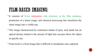
It consistsof X-ray interaction with electrons in the film emulsion,
production of a latent image, and chemical processing that transforms the
latent image into a visible one.
This image characterized by continuous shades of gray, each shade has an
optical density related to the amount of light that can pass throw the object
at specific site.
Final result is a fixed image that is difficult to manipulate once captured.
3.
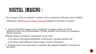
Its animage saved in computer’s memory and is composed of discrete units of digital
information called pixels or picture elements arranged in the form of a matrix.
Conventional film images can be considered an analog medium in which
differences in the size and distribution of black metallic silver result in a continuous
density spectrum.
Digital images are numeric and discrete in two ways:
(1) In terms of the spatial distribution of the picture elements (pixels) and
(2) In terms of the different shades of gray of each of the pixels.
Each pixel has a row and column coordinate that uniquely identifies its location in
the matrix.
4.
The formationof a digital image requires several steps, beginning with
analog processes. At each pixel of an electronic detector, the absorption of x
rays generates a small voltage. More x rays generate a higher voltage and
vice versa.
At each pixel, the voltage can fluctuate between a minimum and
maximum value and is therefore an analog signal.
Production of a digital image requires a process called analog-to-digital
conversion (ADC). ADC consists of two steps: sampling and
quantization.
5.
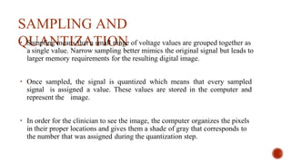
SAMPLING AND
QUANTIZATION
• Samplingmeans that a small range of voltage values are grouped together as
a single value. Narrow sampling better mimics the original signal but leads to
larger memory requirements for the resulting digital image.
• Once sampled, the signal is quantized which means that every sampled
signal is assigned a value. These values are stored in the computer and
represent the image.
• In order for the clinician to see the image, the computer organizes the pixels
in their proper locations and gives them a shade of gray that corresponds to
the number that was assigned during the quantization step.
Old classification accordingto image digitization
1. Indirect digital radiography.
2. Semi direct (PHOTO STIMULABLE PHOSPHOR
DIGITAL RADIOGRAPHIC SYSTEM (PSP)
3. Direct (Charged coupled device (CCD) and
(Complementary metal-oxide semi conductor (CMOS).
8.
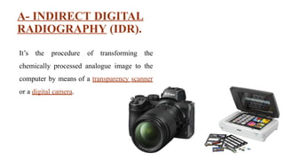
A- INDIRECT DIGITAL
RADIOGRAPHY(IDR).
It’s the procedure of transforming the
chemically processed analogue image to the
computer by means of a transparency scanner
or a digital camera.
9.
B- (SEMI DIRECT)-PHOTO
STIMULABLE PHOSPHOR DIGITAL
RADIOGRAPHIC SYSTEM (PSP)
Photostimulable phosphor plates (PSP) absorb and store energy from x rays and then release this
energy as light (phosphorescence) when stimulated by other light of an appropriate wavelength.
The photostimu1able phosphor material used for radiographic imaging is "Europium-doped"
barium fluorohalide. Barium in combination with iodine, chlorine, or bromine forms a crystal
lattice. The addition of Europium (Eu+2) creates imperfections in this lattice.
When exposed to radiation, valence electrons in Europium can absorb energy and move into the
conduction band. These electrons migrate to nearby halogen vacancies (F-centers) in the
fluorohalide lattice and may become trapped there in a metastable state.
While in this state, the number of trapped electrons is proportional to x-ray exposure and
represents a latent image.
10.
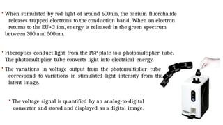
When stimulatedby red light of around 600nm, the barium fluorohalide
releases trapped electrons to the conduction band. When an electron
returns to the EU+3 ion, energy is released in the green spectrum
between 300 and 500nm.
Fiberoptics conduct light from the PSP plate to a photomultiplier tube.
The photomultiplier tube converts light into electrical energy.
The variations in voltage output from the photomultiplier tube
correspond to variations in stimulated light intensity from the
latent image.
The voltage signal is quantified by an analog-to-digital
converter and stored and displayed as a digital image.
11.
Still not solvingall the processing
problems.
Time and effort consuming.
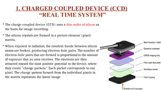
1. CHARGED COUPLEDDEVICE (CCD)
“REAL TIME SYSTEM”
The charge-coupled device (CCD) uses a thin wafer of silicon as
the basis for image recording.
The silicon crystals are formed in a picture element (pixel)
matrix.
When exposed to radiation, the covalent bonds between silicon
atoms are broken, producing electron-hole pairs. The number of
electron-hole pairs that are formed is proportional to the amount
of exposure that an area receives. The electrons are then
attracted toward the most positive potential in the device, where
they create "charge packets." Each packet corresponds to one
pixel. The charge pattern formed from the individual pixels in
the matrix represents the latent image
14.
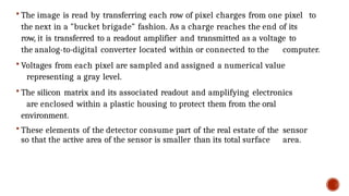
The imageis read by transferring each row of pixel charges from one pixel to
the next in a "bucket brigade" fashion. As a charge reaches the end of its
row, it is transferred to a readout amplifier and transmitted as a voltage to
the analog-to-digital converter located within or connected to the computer.
Voltages from each pixel are sampled and assigned a numerical value
representing a gray level.
The silicon matrix and its associated readout and amplifying electronics
are enclosed within a plastic housing to protect them from the oral
environment.
These elements of the detector consume part of the real estate of the sensor
so that the active area of the sensor is smaller than its total surface area.
15.
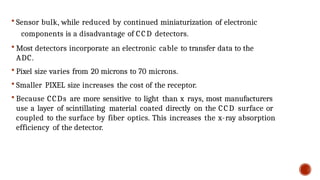
Sensor bulk,while reduced by continued miniaturization of electronic
components is a disadvantage of CCD detectors.
Most detectors incorporate an electronic cable to transfer data to the
ADC.
Pixel size varies from 20 microns to 70 microns.
Smaller PIXEL size increases the cost of the receptor.
Because CCDs are more sensitive to light than x rays, most manufacturers
use a layer of scintillating material coated directly on the CCD surface or
coupled to the surface by fiber optics. This increases the x-ray absorption
efficiency of the detector.
16.
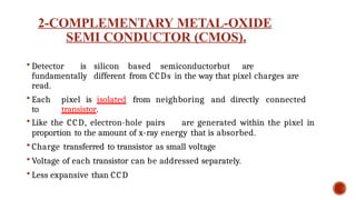
2-COMPLEMENTARY METAL-OXIDE
SEMI CONDUCTOR(CMOS).
Detector is silicon based semiconductorbut are
fundamentally different from CCDs in the way that pixel charges are
read.
Each pixel is isolated from neighboring and directly connected
to transistor.
Like the CCD, electron-hole pairs are generated within the pixel in
proportion to the amount of x-ray energy that is absorbed.
Charge transferred to transistor as small voltage
Voltage of each transistor can be addressed separately.
Less expansive than CCD
17.
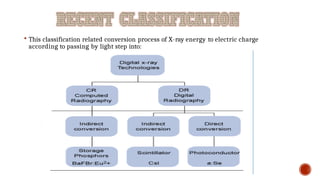
This classificationrelated conversion process of X-ray energy to electric charge
according to passing by light step into:
In-Direct
Computed
radiography
(CR)
18.
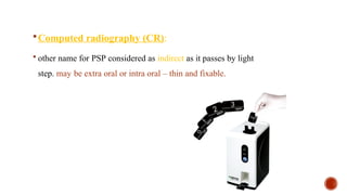
Computed radiography(CR):
other name for PSP considered as indirect as it passes by light
step. may be extra oral or intra oral – thin and fixable.
19.
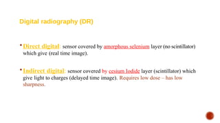
Direct digital:sensor covered by amorphous selenium layer (no scintillator)
which give (real time image).
Indirect digital: sensor covered by cesium Iodide layer (scintillator) which
give light to charges (delayed time image). Requires low dose – has low
sharpness.
Digital radiography (DR)
20.
DIGIT
AL DETECT
OR CHARACTERISTICS
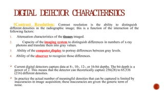
1ContrastResolution: Contrast resolution is the ability to distinguish
different densities in the radiographic image; this is a function of the interaction of the
following factors:
1. Attenuation characteristics of the tissues imaged.
2. Capacity of the imaging system to distinguish differences in numbers of x-ray
photons and translate them into gray values.
3. Ability of the computer display to portray differences between gray levels.
4. Ability of the observer to recognize those differences.
Current digital detectors capture data at 8-, 10-, 12-, or 16-bit depths. The bit depth is a
power of 2. This means that the detector can theoretically capture 256(28) to 65,536
(216) different densities.
In practice the actual number of meaningful densities that can be captured is limited by
inaccuracies in image acquisition; these inaccuracies are given the generic term of
noise.
21.
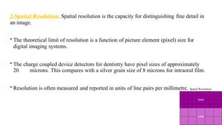
2-Spatial Resolution: Spatialresolution is the capacity for distinguishing fine detail in
an image.
The theoretical limit of resolution is a function of picture element (pixel) size for
digital imaging systems.
The charge coupled device detectors for dentistry have pixel sizes of approximately
20 microns. This compares with a silver grain size of 8 microns for intraoral film.
Resolution is often measured and reported in units of line pairs per millimetre.
22.
Test objectsconsisting of sets of very fine radiopaque lines separated from
each other by spaces equal to the width of a line are constructed with a variety
of line widths . A line and its associated space are called a line pair (lp).
Intraoral film is capable of providing more than 20 lp/mm of resolution.
Unless a film image is magnified, the observer is unable to appreciate the
extent of the
detail in the image.
Current digital systems are capable of providing more than 7lp/mm of
resolution. Software displays of digital images permit magnification of
images.
23.
3-Detector Latitude: Theability of an image receptor to capture a range of x-
ray exposures is termed latitude.
A desirable quality in intraoral image receptors is the ability to record the
full range of tissue densities, from gingiva to enamel.
The latitude of CCD and CMOS detectors is similar to film and can be
extended with digital enhancement of contrast and brightness.
Photostimulable phosphor receptors enjoy larger latitudes and have a linear
response to five orders of magnitude of x-ray exposure.
24.
4-Detector Sensitivity: Thesensitivity, or speed, of a detector is its ability
to respond to small amounts of radiation.
Sensitivity of digital radiography exaggerates the performance that can
actually be achieved in routine practice. Useful sensitivity of digital receptors
is affected by a number of factors including detector efficiency, pixel size, and
system noise.
Current PSP systems for intraoral imaging allow dose reductions of about
50% in comparison with F-speed film.
High resolution CCD and CMOS systems achieve less dose reduction than
lower resolution PSPs systems.
25.
5-Sharpening and Smoothing
The purpose of sharpening and smoothing filters is to improve image quality by
removing blur or noise.
Noise is often categorized as high-frequency noise (speckling) or low-frequency
noise (gradual intensity changes).
Filters that smooth images are sometimes called despeckling filters because they
remove high-frequency noise.
Filters that sharpen an image either remove low-frequency noise or enhance
boundaries between regions with different intensities (edge enhancement).
26.
1. Time saving:
Thedigital image is displayed on the computer monitor either immediately
after exposure (CCD based system) or there is a lag period of 20 to 40
seconds may be needed (PSP based systems).
27.
2. Dose reduction:
Inintra-oral radiography, DDR needs an exposure dose which is 80-90%
less than conventional analogue.
3. Eliminates the possible chemical processing
errors.
4. Space saving.
5. Saving digital image instead of hard one.
6. No need for a dark room or processing chemicals.
28.
5. Image enhancementand manipulation.
1. Image sharpening and edge enhancement.
2. Contrast and brightness enhancement.
3. Zooming
4. Color coding that facilitates interpretation.
5. Black and white (-ve) conversion
6. Highlighting areas of interest.
29.
6. Archiving andrecall of information
7.Better case presentation ,
demonstration and education
8.Electronic exchange of information
and online consultation
9.Possible network building in offices
with multiple operating rooms
11. Standardization andreproducibility in
research work
12. Environmentally friendly ( no lead or
silver )
13. Effective patient education tool
32.
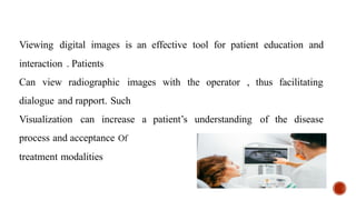
Viewing digital imagesis an effective tool for patient education and
interaction . Patients
Can view radiographic images with the operator , thus facilitating
dialogue and rapport. Such
Visualization can increase a patient’s understanding of the disease
process and acceptance Of
treatment modalities
33.
structures that havenot changed between
This feature permits the operator to remove all anatomic
radiographic
examinations for easy identification of any changes in diagnostic
information. E.g. any changes in bone density or bone
dimensions that may occur during follow up of periodontal
treatment
14. Digital subtraction radiography
(DSR)
34.
Two or morereproducible digital images are similarly ( same
geometric parameters ) made for the patient , the first image is called
initial base-line image that is made before the dental therapy begins ,
while the second image is taken after certain period of time from the
beginning of the dental therapy and is called follow up image .
Method of DSR
35.
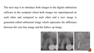
The next stepis to introduce both images to the digital subtraction
software in the computer where both images are superimposed on
each other and compared to each other and a new image is
generated called subtracted image which represents the difference
between the vase line image and the follow up image
36.
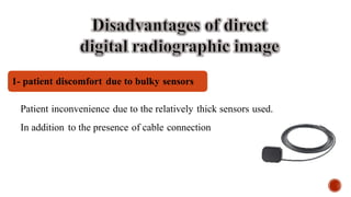
Patient inconvenience dueto the relatively thick sensors used.
In addition to the presence of cable connection
1- patient discomfort due to bulky sensors
37.
2- active arealimitation in certain CCD systems
3inaccessibility to some areas due to the
sensor thickness and cord connection
4 high initial cost
38.
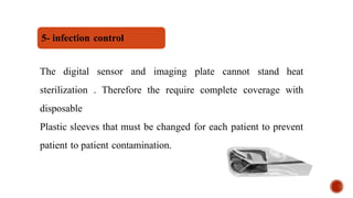
The digital sensorand imaging plate cannot stand heat
sterilization . Therefore the require complete coverage with
disposable
Plastic sleeves that must be changed for each patient to prevent
patient to patient contamination.
5- infection control
39.
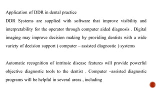
Application of DDRin dental practice
DDR Systems are supplied with software that improve visibility and
interpretability for the operator through computer aided diagnosis . Digital
imaging may improve decision making by providing dentists with a wide
variety of decision support ( computer – assisted diagnostic ) systems
Automatic recognition of intrinsic disease features will provide powerful
objective diagnostic tools to the dentist . Computer –assisted diagnostic
programs will be helpful in several areas , including
41.
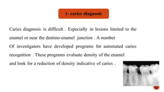
Caries diagnosis isdifficult . Especially in lesions limited to the
enamel or near the dentino-enamel junction . A number
Of investigators have developed programs for automated caries
recognition . These programs evaluate density of the enamel
and look for a reduction of density indicative of caries .
1- caries diagnosis
42.
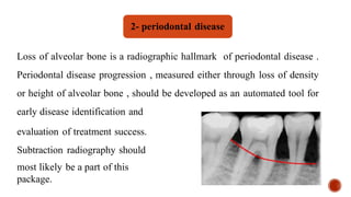
Loss of alveolarbone is a radiographic hallmark of periodontal disease .
Periodontal disease progression , measured either through loss of density
or height of alveolar bone , should be developed as an automated tool for
early disease identification and
evaluation of treatment success.
Subtraction radiography should
most likely be a part of this
package.
2- periodontal disease
43.
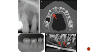
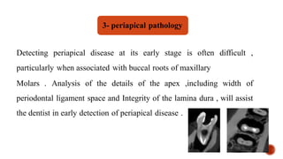
Detecting periapical diseaseat its early stage is often difficult ,
particularly when associated with buccal roots of maxillary
Molars . Analysis of the details of the apex ,including width of
periodontal ligament space and Integrity of the lamina dura , will assist
the dentist in early detection of periapical disease .
3- periapical pathology
44.
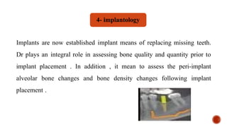
Implants are nowestablished implant means of replacing missing teeth.
Dr plays an integral role in assessing bone quality and quantity prior to
implant placement . In addition , it mean to assess the peri-implant
alveolar bone changes and bone density changes following implant
placement .
4- implantology
45.
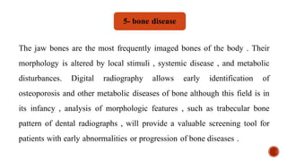
The jaw bonesare the most frequently imaged bones of the body . Their
morphology is altered by local stimuli , systemic disease , and metabolic
disturbances. Digital radiography allows early identification of
osteoporosis and other metabolic diseases of bone although this field is in
its infancy , analysis of morphologic features , such as trabecular bone
pattern of dental radiographs , will provide a valuable screening tool for
patients with early abnormalities or progression of bone diseases .
5- bone disease


![CystS in oral pathology dental edu[1].pptx](https://cdn.slidesharecdn.com/ss_thumbnails/cysts1-250430234019-1ab3f067-thumbnail.jpg?width=640&height=640&fit=bounds)


