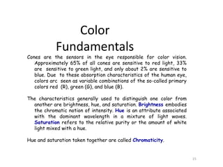
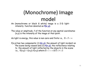
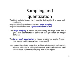
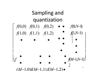
The document covers digital image processing topics such as visual perception, image sensing, and acquisition, including human eye anatomy and the way it perceives color and brightness. It explains concepts like brightness adaptation, color models (RGB and HSI), and the principles of video cameras and charge-coupled devices (CCDs). It further discusses image sampling, quantization, and the implications of spatial and gray-level resolution on digital images.
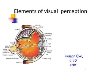
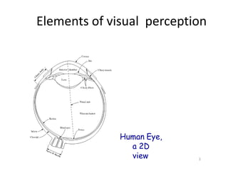

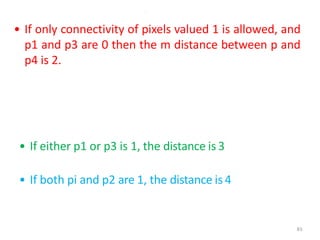
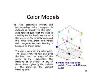
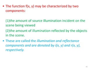
![A color model (also called color space or color system) is a
specification of a coordinate system and a subspace within that
system where each color is represented by a single point.
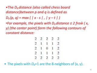
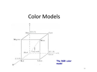
The RGB color model: In the RGB model, each color appears in its
primary spectral components of red, green, and blue. This model
is based on a Cartesian coordinate system. The color subspace
is the cube in which RGB values are at three corners; cyan,
magenta, and yellow are at three other corners; black is at the
origin; and white is at the corner farthest from the origin.
The gray scale (points of equal RGB values) extends from black to
white along the diagonal line joining these two points.
The different colors are points on or inside the cube, and are
defined by vectors extending from the origin.
All values of R, G. and B are assumed to be in the range [0, 1].
17
Color Models](https://image.slidesharecdn.com/day2-visualperception-200627104208/85/DIGITAL-IMAGE-PROCESSING-Visual-perception-DAY-2-17-320.jpg)


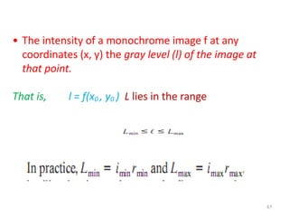
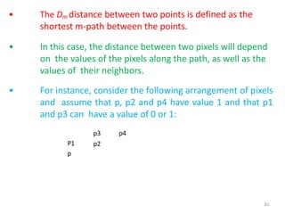
![68
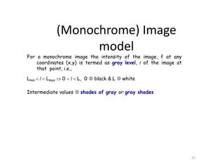
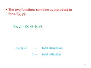
GRAY SCALE
• The interval [Lmin , Lmax ] is called thegray scale.
• Common practice is to shift this interval numerically to
the interval [0, L-1],
• where L = 0 is considered black and
L = L-1 is considered white on the gray scale.
All intermediate values are shades of gray varying from
black to white.](https://image.slidesharecdn.com/day2-visualperception-200627104208/85/DIGITAL-IMAGE-PROCESSING-Visual-perception-DAY-2-68-320.jpg)