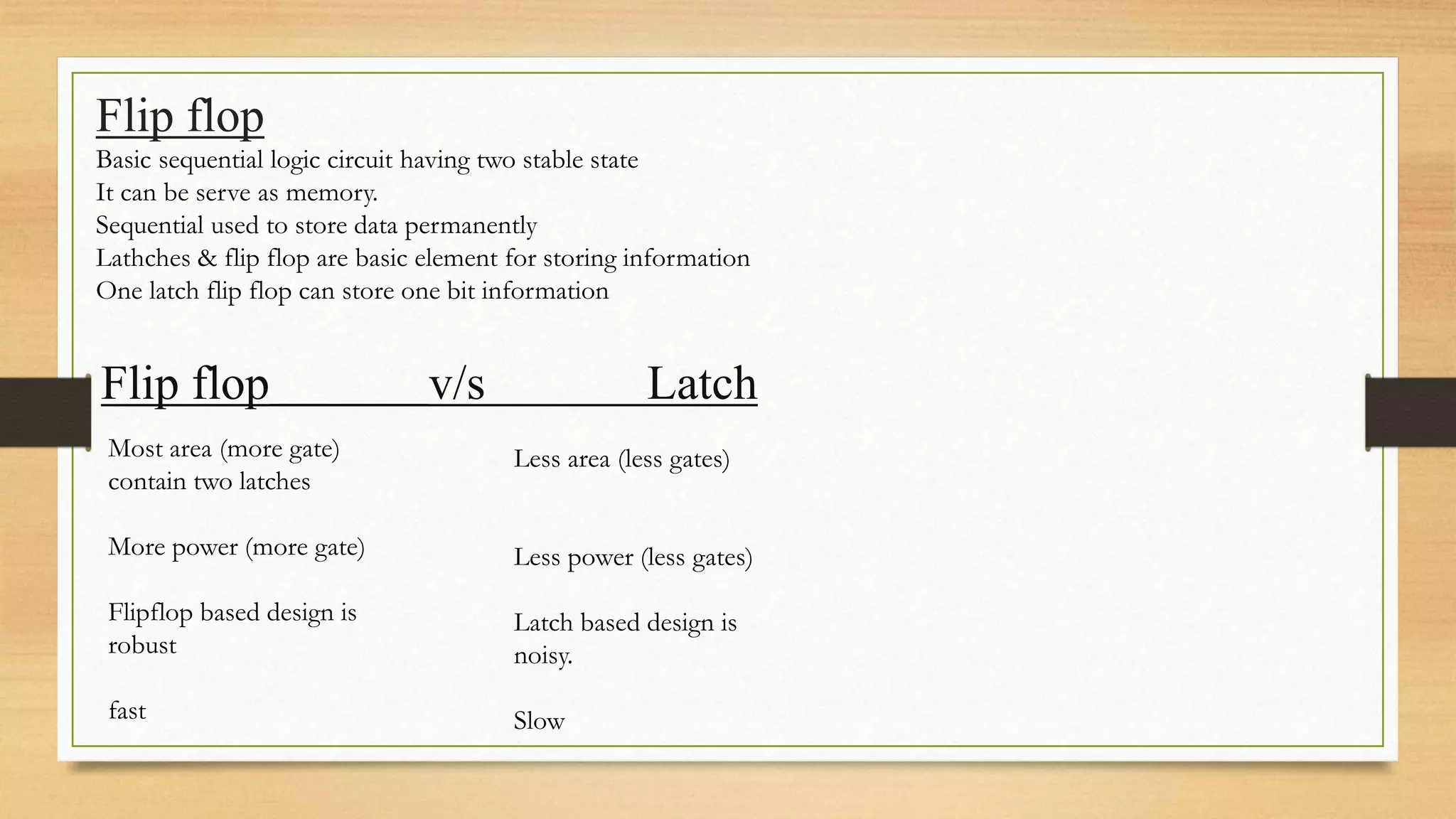
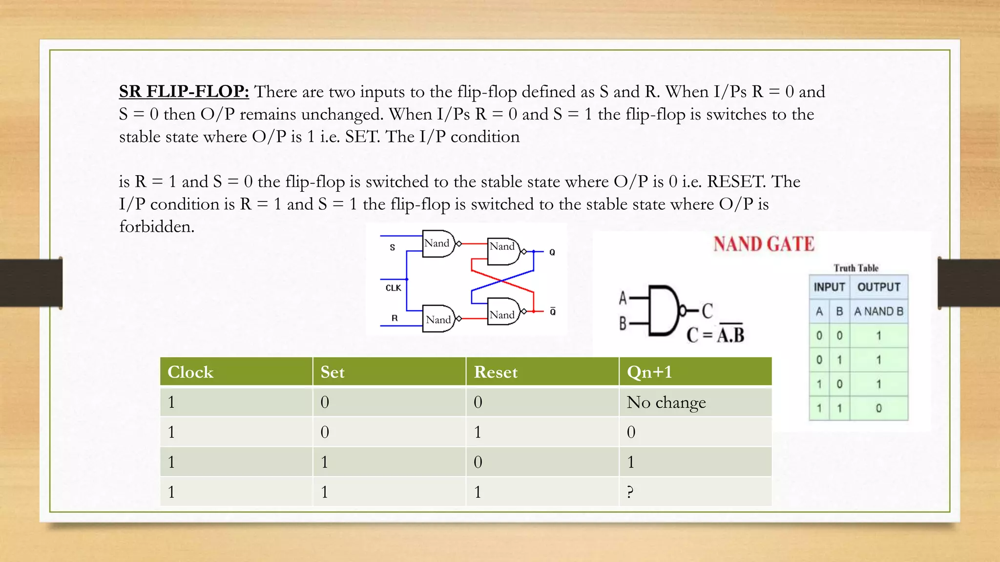
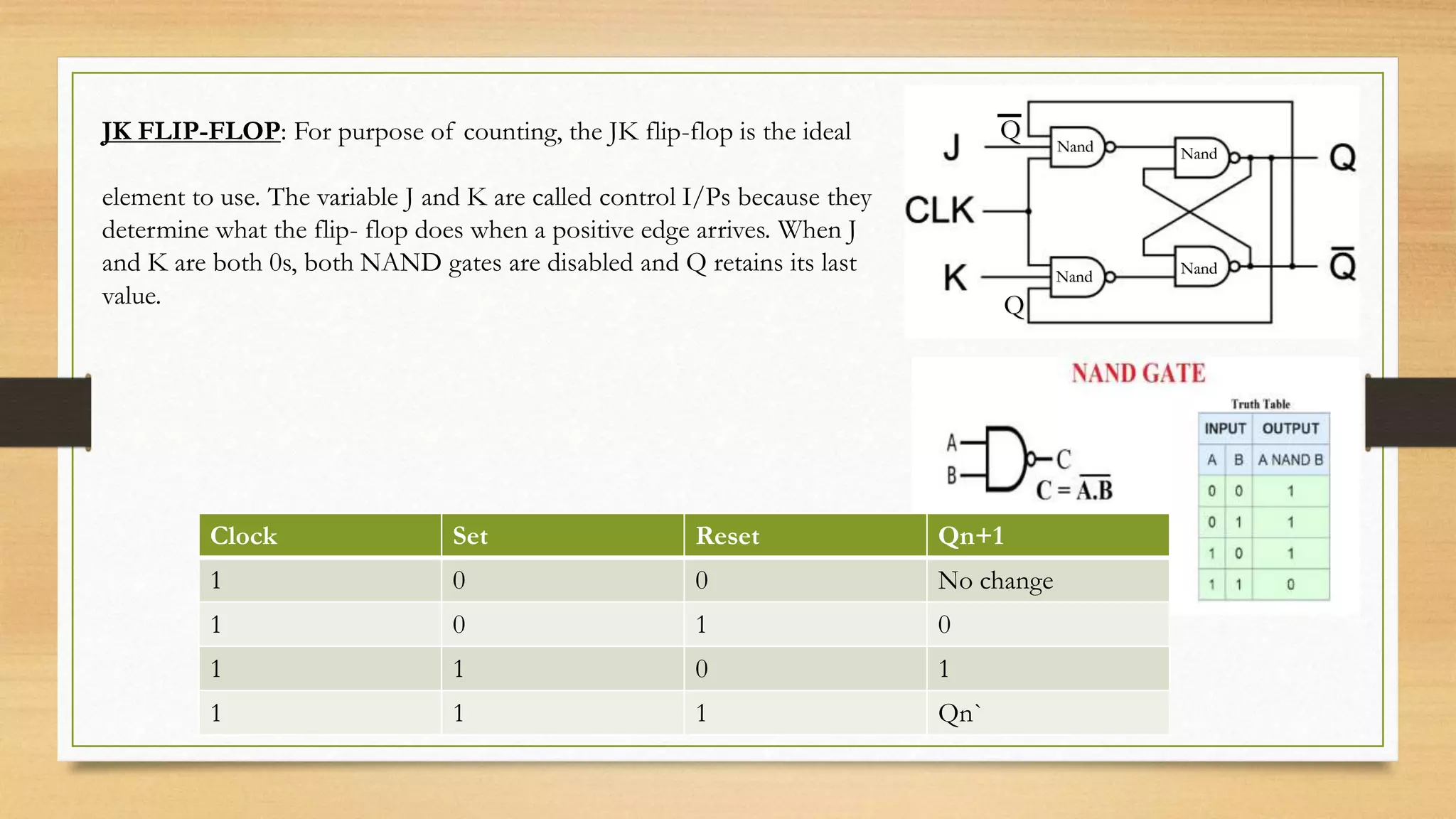
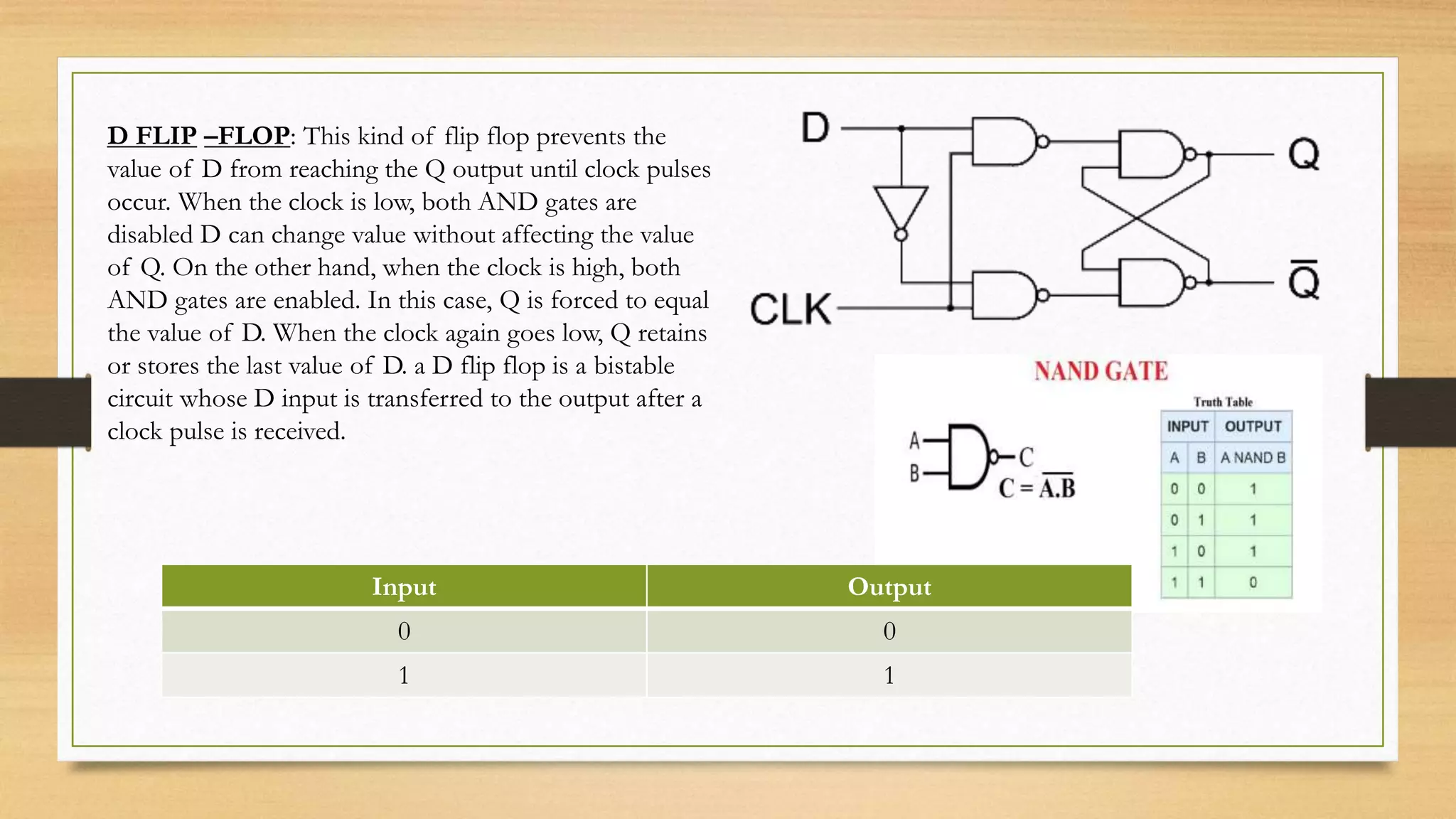
Topic
Flip flop
Group members
Muhammad Areeb
Muhaammad Anus
Hamza Akhter 3rd semester
Zeeshan feroz
Flip flop
Basic sequential logic circuit having two stable state
It can be serve as memory.
Sequential used to store data permanently
Lathches & flip flop are basic element for storing information
One latch flip flop can store one bit information
Flip flop v/s Latch
Most area (more gate)
contain two latches
More power (more gate)
Flipflop based design is
robust
fast
Less area (less gates)
Less power (less gates)
Latch based design is
noisy.
Slow
SR FLIP-FLOP: There are two inputs to the flip-flop defined as S and R. When I/Ps R = 0 and
S = 0 then O/P remains unchanged. When I/Ps R = 0 and S = 1 the flip-flop is switches to the
stable state where O/P is 1 i.e. SET. The I/P condition
is R = 1 and S = 0 the flip-flop is switched to the stable state where O/P is 0 i.e. RESET. The
I/P condition is R = 1 and S = 1 the flip-flop is switched to the stable state where O/P is
forbidden.
Nand
Nand
Nand
Nand
Clock Set Reset Qn+1
1 0 0 No change
1 0 1 0
1 1 0 1
1 1 1 ?
JK FLIP-FLOP: For purpose of counting, the JK flip-flop is the ideal
element to use. The variable J and K are called control I/Ps because they
determine what the flip- flop does when a positive edge arrives. When J
and K are both 0s, both NAND gates are disabled and Q retains its last
value.
Nand
Nand Nand
Nand
Clock Set Reset Qn+1
1 0 0 No change
1 0 1 0
1 1 0 1
1 1 1 Qn`
Q
Q
D FLIP –FLOP: This kind of flip flop prevents the
value of D from reaching the Q output until clock pulses
occur. When the clock is low, both AND gates are
disabled D can change value without affecting the value
of Q. On the other hand, when the clock is high, both
AND gates are enabled. In this case, Q is forced to equal
the value of D. When the clock again goes low, Q retains
or stores the last value of D. a D flip flop is a bistable
circuit whose D input is transferred to the output after a
clock pulse is received.
Input Output
0 0
1 1
T FLIP-FLOP: The T or "toggle" flip-flop changes its
output on each clock edge, giving an output which is half
the frequency of the signal to the T input. It is useful for
constructing binary counters, frequency dividers, and
general binary addition devices. It can be made from a J-
K flip-flop by tying both of its inputs high.
Clock Set Reset Qn+1
1 0 1 Nochange
1 1 0 Qn’

Digital electronics Flip Flop

  • 1.
    Topic Flip flop Group members MuhammadAreeb Muhaammad Anus Hamza Akhter 3rd semester Zeeshan feroz
  • 2.
    Flip flop Basic sequentiallogic circuit having two stable state It can be serve as memory. Sequential used to store data permanently Lathches & flip flop are basic element for storing information One latch flip flop can store one bit information Flip flop v/s Latch Most area (more gate) contain two latches More power (more gate) Flipflop based design is robust fast Less area (less gates) Less power (less gates) Latch based design is noisy. Slow
  • 3.
    SR FLIP-FLOP: Thereare two inputs to the flip-flop defined as S and R. When I/Ps R = 0 and S = 0 then O/P remains unchanged. When I/Ps R = 0 and S = 1 the flip-flop is switches to the stable state where O/P is 1 i.e. SET. The I/P condition is R = 1 and S = 0 the flip-flop is switched to the stable state where O/P is 0 i.e. RESET. The I/P condition is R = 1 and S = 1 the flip-flop is switched to the stable state where O/P is forbidden. Nand Nand Nand Nand Clock Set Reset Qn+1 1 0 0 No change 1 0 1 0 1 1 0 1 1 1 1 ?
  • 4.
    JK FLIP-FLOP: Forpurpose of counting, the JK flip-flop is the ideal element to use. The variable J and K are called control I/Ps because they determine what the flip- flop does when a positive edge arrives. When J and K are both 0s, both NAND gates are disabled and Q retains its last value. Nand Nand Nand Nand Clock Set Reset Qn+1 1 0 0 No change 1 0 1 0 1 1 0 1 1 1 1 Qn` Q Q
  • 5.
    D FLIP –FLOP:This kind of flip flop prevents the value of D from reaching the Q output until clock pulses occur. When the clock is low, both AND gates are disabled D can change value without affecting the value of Q. On the other hand, when the clock is high, both AND gates are enabled. In this case, Q is forced to equal the value of D. When the clock again goes low, Q retains or stores the last value of D. a D flip flop is a bistable circuit whose D input is transferred to the output after a clock pulse is received. Input Output 0 0 1 1
  • 6.
    T FLIP-FLOP: TheT or "toggle" flip-flop changes its output on each clock edge, giving an output which is half the frequency of the signal to the T input. It is useful for constructing binary counters, frequency dividers, and general binary addition devices. It can be made from a J- K flip-flop by tying both of its inputs high. Clock Set Reset Qn+1 1 0 1 Nochange 1 1 0 Qn’