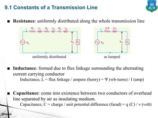
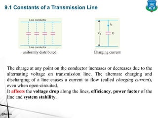
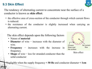
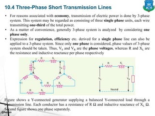
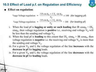
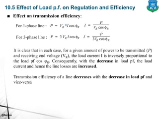
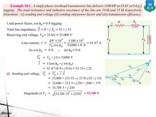
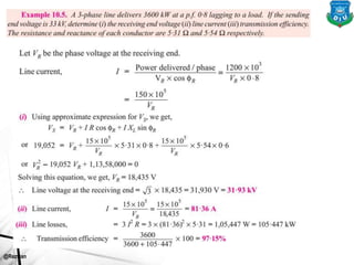
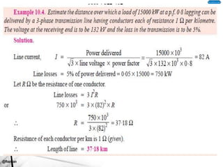
EEE 441
Transmission & Distribution of Electrical Power
Transmission Line & Skin Effect
 Constants of Transmission Lines
 Skin Effect
 Classification of Overhead Transmission Lines
 Performance of Single Phase Short Transmission Lines
 Three-Phase Short Transmission Lines
 Effect of Load p.f. on Regulation and Efficiency
 Medium Transmission Lines and solution methods
 End Condenser Method to solve Medium transmission
line
Lecture Contents
Learning Outcomes
• The students will be able to
 develop formulas by which we can calculate voltage regulation,
line losses and efficiency of transmission lines
 understand the effects of the parameters of the line on bus
voltages and the flow of power
 realize overall understanding of what is occurring on electric
power system
 apply different methods for solving short, medium and long
transmission lines
Introduction
• The important considerations in the design and operation of a
transmission line are the determination of voltage drop, line
losses and efficiency of transmission. These values are greatly
influenced by the line constants R, L and C of the transmission
line. For instance, the voltage drop in the line depends upon the
values of above three line constants. Similarly, the resistance of
transmission line conductors is the most important cause of
power loss in the line and determines the transmission
efficiency. Through out this module, we will develop and apply
formulas by which we can calculate voltage regulation, line
losses and efficiency of transmission lines.
@Rezwan
9.1 Constants of a Transmission Line
■ Inductance: formed due to flux linkage surrounding the alternating
current carrying conductor
Inductance, L = flux linkage / ampere (henry) = Ψ (wb-turns) / I (amp)
■ Resistance: uniformly distributed along the whole transmission line
uniformly distributed as lumped
■ Capacitance: come into existence between two conductors of overhead
line separated by air as insulating medium.
Capacitance, C = charge / unit potential difference (farad) = q (C) / v (volt)
@Rezwan
9.1 Constants of a Transmission Line
The charge at any point on the conductor increases or decreases due to the
alternating voltage on transmission line. The alternate charging and
discharging of a line causes a current to flow (called charging current),
even when open-circuited.
It affects the voltage drop along the lines, efficiency, power factor of the
line and system stability.
uniformly distributed Charging current
@Rezwan
9.3 Skin Effect
The tendency of alternating current to concentrate near the surface of a
conductor is known as skin effect.
Skin effect
• the effective area of cross-section of the conductor through which current flows
is reduced.
• the resistance of the conductor is slightly increased when carrying an
alternating current.
The skin effect depends upon the following factors
• Nature of material
• Diameter of wire − increases with the diameter of
wire.
• Frequency − increases with the increase in
frequency.
• Shape of wire − less for stranded conductor than the
solid conductor
Negligible when the supply frequency < 50 Hz and conductor diameter < 1cm
@Rezwan
10.1 Classification of Overhead Transmission Lines
A transmission line has three constants R-L (series impedance) and C
(shunt path) distributed uniformly along the whole length of the line.
Depending on handling of capacitance (complications in TL calculations) -
■ Short TL: overhead TL is upto about 50 km and line voltage is
comparatively low (<20 kV). Due to smaller length and lower voltage,
capacitance effects are small and can be neglected.
■ Medium TL: overhead TL is about 50-150 km and line voltage is
moderately high (>20 kV, <100 kV). Due to sufficient length and line
voltage, capacitance effects have to be considered. Calculations –
distributed capacitance is divided and lumped in the form of
condensers shunted across the line at one or more points.
■ Long TL: overhead TL is >150 km and line voltage is very high (>100
kV). Calculation - line constants are considered uniformly distributed
over the whole length of the line and rigorous methods are employed
for solution.
@Rezwan
10.2 Important Terms
■ Voltage regulation: The difference in voltage at the receiving end of a
transmission line between conditions of no load and full load is called
voltage regulation and is expressed as a percentage of the receiving end
voltage.
■ Transmission efficiency : The ratio of receiving end power to the
sending end power of a transmission line is known as the transmission
efficiency of the line
@Rezwan
10.3 Performance of Short Transmission Lines
Effects of capacitance are neglected, only resistance and inductance are
considered.
lagging load power factor
From the right angled triangle ODC, we get
@Rezwan
10.3 Performance of Short Transmission Lines
Approximate expression of Vs
Draw perpendicular from B and C on OA produced. Then
OC is nearly equal to OF.
@Rezwan
10.3 Performance of Short Transmission Lines
Complex Notation
@Rezwan
10.4 Three-Phase Short Transmission Lines
Figure shows a Y-connected generator supplying a balanced Y-connected load through a
transmission line. Each conductor has a resistance of R Ω and inductive reactance of XL Ω.
Second figure shows one phase separately.
• For reasons associated with economy, transmission of electric power is done by 3-phase
system. This system may be regarded as consisting of three single phase units, each wire
transmitting one-third of the total power.
• As a matter of convenience, generally 3-phase system is analyzed by considering one
phase only.
• Expression for regulation, efficiency etc. derived for a single phase line can also be
applied to a 3-phase system. Since only one phase is considered, phase values of 3-phase
system should be taken. Thus, VS and VR are the phase voltages, whereas R and XL are
the resistance and inductive reactance per phase respectively
@Rezwan
10.5 Effect of Load p.f. on Regulation and Efficiency
■ Effect on regulation:
(for lagging pf)
(for leading pf)
i. When the load pf is lagging or unity or such leading that IR cosφR > IXL
sinφR, then voltage regulation is positive i.e., receiving end voltage VR will
be less than the sending end voltage VS.
ii. When the load pf is leading to this extent that IXL sinφR > IR cosφR, then
voltage regulation is negative i.e. the receiving end voltage VR is more than
the sending end voltage VS.
iii. For a given VR and I, the voltage regulation of the line increases with the
decrease in pf for lagging loads.
iv. For a given VR and I, the voltage regulation of the line decreases with the
decrease in pf for leading loads.
@Rezwan
10.5 Effect of Load p.f. on Regulation and Efficiency
■ Effect on transmission efficiency:
For 1-phase line :
For 3-phase line :
It is clear that in each case, for a given amount of power to be transmitted (P)
and receiving end voltage (VR), the load current I is inversely proportional to
the load pf cos φR. Consequently, with the decrease in load pf, the load
current and hence the line losses are increased.
Transmission efficiency of a line decreases with the decrease in load pf and
vice-versa
@Rezwan
@Rezwan
@Rezwan
@Rezwan
@Rezwan
@Rezwan
@Rezwan

Module-2 Short Line and Problems (1) - Copy.pptx

  • 1.
    EEE 441 Transmission &Distribution of Electrical Power Transmission Line & Skin Effect
  • 2.
     Constants ofTransmission Lines  Skin Effect  Classification of Overhead Transmission Lines  Performance of Single Phase Short Transmission Lines  Three-Phase Short Transmission Lines  Effect of Load p.f. on Regulation and Efficiency  Medium Transmission Lines and solution methods  End Condenser Method to solve Medium transmission line Lecture Contents
  • 3.
    Learning Outcomes • Thestudents will be able to  develop formulas by which we can calculate voltage regulation, line losses and efficiency of transmission lines  understand the effects of the parameters of the line on bus voltages and the flow of power  realize overall understanding of what is occurring on electric power system  apply different methods for solving short, medium and long transmission lines
  • 4.
    Introduction • The importantconsiderations in the design and operation of a transmission line are the determination of voltage drop, line losses and efficiency of transmission. These values are greatly influenced by the line constants R, L and C of the transmission line. For instance, the voltage drop in the line depends upon the values of above three line constants. Similarly, the resistance of transmission line conductors is the most important cause of power loss in the line and determines the transmission efficiency. Through out this module, we will develop and apply formulas by which we can calculate voltage regulation, line losses and efficiency of transmission lines.
  • 5.
    @Rezwan 9.1 Constants ofa Transmission Line ■ Inductance: formed due to flux linkage surrounding the alternating current carrying conductor Inductance, L = flux linkage / ampere (henry) = Ψ (wb-turns) / I (amp) ■ Resistance: uniformly distributed along the whole transmission line uniformly distributed as lumped ■ Capacitance: come into existence between two conductors of overhead line separated by air as insulating medium. Capacitance, C = charge / unit potential difference (farad) = q (C) / v (volt)
  • 6.
    @Rezwan 9.1 Constants ofa Transmission Line The charge at any point on the conductor increases or decreases due to the alternating voltage on transmission line. The alternate charging and discharging of a line causes a current to flow (called charging current), even when open-circuited. It affects the voltage drop along the lines, efficiency, power factor of the line and system stability. uniformly distributed Charging current
  • 7.
    @Rezwan 9.3 Skin Effect Thetendency of alternating current to concentrate near the surface of a conductor is known as skin effect. Skin effect • the effective area of cross-section of the conductor through which current flows is reduced. • the resistance of the conductor is slightly increased when carrying an alternating current. The skin effect depends upon the following factors • Nature of material • Diameter of wire − increases with the diameter of wire. • Frequency − increases with the increase in frequency. • Shape of wire − less for stranded conductor than the solid conductor Negligible when the supply frequency < 50 Hz and conductor diameter < 1cm
  • 8.
    @Rezwan 10.1 Classification ofOverhead Transmission Lines A transmission line has three constants R-L (series impedance) and C (shunt path) distributed uniformly along the whole length of the line. Depending on handling of capacitance (complications in TL calculations) - ■ Short TL: overhead TL is upto about 50 km and line voltage is comparatively low (<20 kV). Due to smaller length and lower voltage, capacitance effects are small and can be neglected. ■ Medium TL: overhead TL is about 50-150 km and line voltage is moderately high (>20 kV, <100 kV). Due to sufficient length and line voltage, capacitance effects have to be considered. Calculations – distributed capacitance is divided and lumped in the form of condensers shunted across the line at one or more points. ■ Long TL: overhead TL is >150 km and line voltage is very high (>100 kV). Calculation - line constants are considered uniformly distributed over the whole length of the line and rigorous methods are employed for solution.
  • 9.
    @Rezwan 10.2 Important Terms ■Voltage regulation: The difference in voltage at the receiving end of a transmission line between conditions of no load and full load is called voltage regulation and is expressed as a percentage of the receiving end voltage. ■ Transmission efficiency : The ratio of receiving end power to the sending end power of a transmission line is known as the transmission efficiency of the line
  • 10.
    @Rezwan 10.3 Performance ofShort Transmission Lines Effects of capacitance are neglected, only resistance and inductance are considered. lagging load power factor From the right angled triangle ODC, we get
  • 11.
    @Rezwan 10.3 Performance ofShort Transmission Lines Approximate expression of Vs Draw perpendicular from B and C on OA produced. Then OC is nearly equal to OF.
  • 12.
    @Rezwan 10.3 Performance ofShort Transmission Lines Complex Notation
  • 13.
    @Rezwan 10.4 Three-Phase ShortTransmission Lines Figure shows a Y-connected generator supplying a balanced Y-connected load through a transmission line. Each conductor has a resistance of R Ω and inductive reactance of XL Ω. Second figure shows one phase separately. • For reasons associated with economy, transmission of electric power is done by 3-phase system. This system may be regarded as consisting of three single phase units, each wire transmitting one-third of the total power. • As a matter of convenience, generally 3-phase system is analyzed by considering one phase only. • Expression for regulation, efficiency etc. derived for a single phase line can also be applied to a 3-phase system. Since only one phase is considered, phase values of 3-phase system should be taken. Thus, VS and VR are the phase voltages, whereas R and XL are the resistance and inductive reactance per phase respectively
  • 14.
    @Rezwan 10.5 Effect ofLoad p.f. on Regulation and Efficiency ■ Effect on regulation: (for lagging pf) (for leading pf) i. When the load pf is lagging or unity or such leading that IR cosφR > IXL sinφR, then voltage regulation is positive i.e., receiving end voltage VR will be less than the sending end voltage VS. ii. When the load pf is leading to this extent that IXL sinφR > IR cosφR, then voltage regulation is negative i.e. the receiving end voltage VR is more than the sending end voltage VS. iii. For a given VR and I, the voltage regulation of the line increases with the decrease in pf for lagging loads. iv. For a given VR and I, the voltage regulation of the line decreases with the decrease in pf for leading loads.
  • 15.
    @Rezwan 10.5 Effect ofLoad p.f. on Regulation and Efficiency ■ Effect on transmission efficiency: For 1-phase line : For 3-phase line : It is clear that in each case, for a given amount of power to be transmitted (P) and receiving end voltage (VR), the load current I is inversely proportional to the load pf cos φR. Consequently, with the decrease in load pf, the load current and hence the line losses are increased. Transmission efficiency of a line decreases with the decrease in load pf and vice-versa
  • 16.
  • 17.
  • 18.
  • 19.
  • 20.
  • 21.
  • 22.