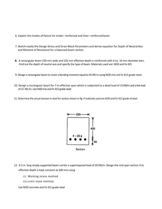
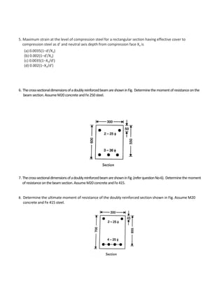
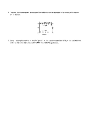
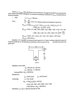
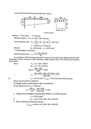
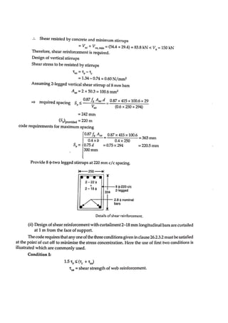
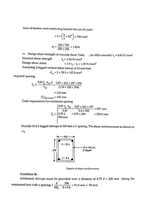
Design Of concrete Structure – I
1. To determine the modulus of rupture, the size of test specimen used is
a) 150 x150 x500 mm
b) 100 x100 x700 mm
c) 150 x150 x700 mm
d) 100 x100 x500 mm
2.The property of fresh concrete, in which the water in the mix tends to rise to the surface while placing
and compacting is called
a) segregation
b) bleeding
c) bulking
d) creep
3. Select the incorrect statement
a) Lean mixes bleed more as compared to rich ones.
b) Bleeding can be minimized by adding pozzuolana finer aggregate.
c) Bleeding can be increased by addition ‘of calcium chloride.
d) none of the above
4. The property of the ingredients to separate from each other while placing the concrete is called
a) segregation
b) compaction
c) shrinkage
d) bulking
5. The factor of safety for
a) steel and concrete are same
b) steel is lower than that for concrete
c) steel is higher than that for concrete
d) none of the above
6. Examine the following statements :
i) Factor of safety for steel should be based on its yield stress,
ii) Factor of safety for steel should be based on its ultimate stress,
iii) Factor of safety for concrete should be based on its yield stress,
iv) Factor of safety for concrete should be based on its ultimate stress.
INTRODUCTION
The correct statements are
a) (i) and (iii)
b) (i)and(iv)
c) (ii) and (iii)
d) (ii) and (iv)
7. Explain Working stress method and Limit state method of structural DesignPhilosophy
8. Define (i) Limit State (ii) Characteristic strength (iii) Partial Safety Factor
9. Write Advantages and Disadvantages of R.C.C. Structures.
10. Discuss different kinds of loads to be taken into account for the design
1. If the depth of actual neutral axis in a beam is more than the depth of critical neutral axis, then the beam
is called
a) balanced beam
b) under-reinforced beam
c) over-reinforced beam
d) none of the above
2 Maximum quantity of water needed per 50 kg of cement for M 15 grade of concrete is
a) 28 liters
b) 30 liters
c) 32 liters
d) 34 liters
3. Minimum grade of concrete to be used in reinforced concrete as per IS: 456-1978 is
a) M15
b) M20
c) M10
d) M25
4. Modulus of elasticity of steel as per IS : 456-2000 shall be takenas
a) 20 kN/cm2
b) 200 kN/cm2
c) 200kN/mm2
d) 2xl06
N/cm2
5.For a simply supported beam of span 15m, the minimum effective depth to satisfy the vertical deflection
limits should be
a) 600 mm
b) 750 mm
c) 900 mm
d) more than 1 m
DESIGN OF BEAMS : SINGLY REINFORCED BEAM
6. Explain the modes of failure for Under- reinforced and Over- reinforced beam
7. Sketch neatly the Design Stress and Strain Block Parameters and derive equation for Depth of NeutralAxis
and Moment of Resistance for a balanced beam section
8. A rectangular beam 230 mm wide and 520 mm effective depth is reinforced with 4 no. 16 mm diameter bars.
Find out the depth of neutral axis and specify the type of beam. Materials used are: M20 and Fe 425
9. Design a rectangular beam to resist a bending moment equal to 45 KN-m using M20 mix and Fe 415 grade steel.
10. Design a rectangular beam for 7 m effective span which is subjected to a dead load of 15KN/mandaliveload
of12 KN/m.UseM20mixandFe415gradesteel
11.Determinetheactualstressesinsteelforsectionshowninfig.ifmaterialsusedareM20andFe415gradeofsteel.
12. A 5 m long simply supported beam carries a superimposed load of 20 KN/m. Design the mid span section if its
effective depth is kept constant at 500 mm using
(i) Working stress method
(ii) Limit state method.
Use M20 concrete and Fe 415 grade steel
13. A reinforced concrete beam has width equal to 300 nun and total depth equal to 800 mm with a cover
of 40 mm to the Centre of reinforcement. Design the beam if it is subjected to a total bending
moment of 140 KN-m. Use M20 concrete and Fe 415 grade steel. Compare the design with that obtained
by working stress method.
1. If the depth of actual neutral axis of a doubly reinforced beam
(a) Is greater than the depth of critical neutral axis, the concrete attains its maximum stressearlier
(b) Is less than the depth of critical neutral axis, the steel in the tensile zone attains its maximum stress
earlier
(c) Is equal to the depth of critical neutral axis; the concrete and steel attain their maximum stresses
Simultaneously
(d) All the above
2. The minimum thickness of the cover at the end of a reinforcing bar should not be less than twicethe
diameter of the bar subject to a minimum of
(a) 10 mm
(b) 15 mm
(c) 20 mm
(d) 25 mm
3. A higher modular ratio shows
(a) higher compressive strength of concrete
(b) lower compressive strength of concrete
(c) higher tensile strength of steel
(d) lower tensile strength of steel
4. According to the steel beam theory of doubly reinforced beams
(a) Tension is resisted by tension steel
(b) Compression is resisted by compression steel
(c) Stress in tension steel equals the stress in compression steel
(d) All the above
DESIGN OF BEAM : DOUBLY REINFORCED BEAM
5. Maximum strain at the level of compression steel for a rectangular section having effective cover to
compression steel as d′ and neutral axis depth from compression face Xu is
(a) 0.0035(1−d′/Xu)
(b) 0.002(1−d′/Xu)
(c) 0.0035(1−Xu/d′)
(d) 0.002(1−Xu/d′)
6. Thecross-sectionaldimensionsofadoublyreinforcedbeamareshowninFig. Determinethemomentofresistanceonthe
beamsection.AssumeM20concreteandFe250steel.
7. Thecross-sectionaldimensionsofadoublyreinforcedbeamareshowninFig.(referquestionNo-6). Determinethemoment
ofresistanceonthebeamsection.AssumeM20concreteandFe415.
8. Determine the ultimate moment of resistance of the doubly reinforced section shown in Fig. Assume M20
concrete and Fe 415 steel.
9. Determinetheultimatemomentofresistanceofthedoublyreinforcedsectionshownin Fig. Assume M20 concrete
and Fe 250 steel.
10. Design a rectangular beam for an effective span of 6 m. The superimposed load is 80 KN/m and size of beam is
limited to 300 mm x 700 mm overall. Use M20 mix and Fe 415 grade steel.
1. A T-beam behaves as a rectangular beam of a width equal to its flange if it’s neutral axis
(a) Remains within the flange
(b) Remains below the slab
(c) Coincides the geometrical centre of the beam
(d) None of these
2. For the design of a simply supported T-beam the ratio of the effective span to the overall depth of the
Beam is limited to
(a) 10
(b) 15
(c) 20
(d) 25
3. The width of the rib of a T-beam, is generally kept between
(a) 1/7 to 1/3 of rib depth
(b) 1/3 to 1/2 of rib depth
(c) 1/2 to 3/4 of rib depth
(d) 1/3 to 2/3 of rib depth
4. The neutral axis of a T-beam exists
(a) Within the flange
(b) At the bottom edge of the slab
(c ) Below the slab
(d) All the above
5. The width of the flange of a T-beam should be less than
(a) One-third of the effective span of the T-beam
(b) Distance between the centres of T-beam
(c) Breadth of the rib plus twelve times the thickness of the slab
(d) Least of the above
DESIGN OF BEAM: FLANGED – BEAM
6. The width of the flange of a L-beam, should be less than
(a) One-sixth of the effective span
(b) Breadth of the rib + four times thickness of the slab
(c) Breadth of the rib + half clear distance between ribs
(d)Least of the above
7. Findthemoment of resistance of T-beam havingfollowing data in Fig.Use M20 mixofconcreteandFe415grade steel.
8. Determine the moment of resistance of T-beam having effective depth 400 mm ,flange width 740 mm ,flange
thickness 90 mm ,web thickness 240 mm and area of tension steel is 5-20 mm dia .Use M 20 and Fe 415.
9. Calculate the moment of resistance of a T-beam as shown in Fig. assumingM20mixandFe415steel.
10. Find the moment of resistance of L.-beam having following data in Fig. UseM20 mix and Fe 415 grade steel.
11. AT-beam has bi=1200mm, btu -=275 mm, d= 600mm andDf=120 mm. Findthe reinforcement for a factored
moment of resistance of
(a) 375
(b) 625
(c) 860 kN-m.
Use M20 mixandFe415 grade steel.
12. Calculate the moment of resistance of a T-beam as shown in Fig. assuming M15 mix and Fe 415 grade steel.
13. Determine the moment of resistance of T-beam of question 12 if Ast = 6-25 mm dia. and Asc = 2-20
mm dia. bars are used.
14. CalculatetheamountofsteelrequiredinaT-beamtodevelopafactoredmomentofresistance of 450 KN-m .The
dimensions of the beam section are given in Fig. Use M20 mix and Fe 415 gradesteel.
BOND AND TORSION
1. Torsion resisting capacity of a given reinforced concrete section
(a) Decreases with decrease in stirrups spacing
(b) Decreases with increase in longitudinal bars
(c) Does not depend upon longitudinal bars and stirrups
(d) Increases with increase in longitudinal bars and stirrups spacing
2. The transverse torsional reinforcement in RCC beams can be provided as
(a) Like ties
(b) Closed loops only
(c) Open or closed loops
(d) Helical loop only.
3. Discuss the procedure for the design of beam subjected to combined bending and torsion in
concrete.
4. A simply supported beam is 260 mm by 520 mm and has 2-20 mm HYSD bars going in to the support. If the
shear force at the center of support is 115 KN at working loads, determine the anchorage length. Assume
M20 and Fe 415.
5. A continuous beam 250x 450 mm carries 3-16 mm longitudinal bars beyond the point of inflection in the lagging
moment region as shown in Fig. The shear force at the point of inflection is 110 KN at working loads. Check if the
beam is safe in bond. Use M20 and Fe 415. Fig. as shown below.
6. A rectangular beam of size 230mm x 400 mm overall depth, is reinforced with 2-10 mm bars at top and 3-16
mm at bottom being tension reinforcement. It is subjected to characteristic loads, shear force of 18 KN, a
torsional moment of 1.2 KN-M and bending moment of 18 KN-m. Check torsion reinforcement. Assume M 20
and Fe 415.
7. A beam of rectangular section is a multistory frame 250 mm x 500 mm deep. The section is subjected to
an ultimate bending moment 55 KN-m, ultimate torsional moment 30 KN-m and ultimate shear force
40 KN. Using M 20 and Fe 415.Design suitable reinforcement in section. Effective cover to steel=50 mm.
1. The maximum shear stress in concrete of are in forced cement concrete beam is
(a) Shear force/(Lever arm × Width)
(b) Lever arm/(Shear force × Width)
(c) Width /(Lever arm × shear force)
(d) None of these
2. The shear capacity of an RCC beam without shear reinforcement is
(a) 𝛕𝐜bd
(b) 𝛕𝐯bd
(c) 𝛕𝐯bd²
(d) 𝛕𝐯bd²
3. Shear reinforcement is provided in the form of :
(a) Vertical bars
(b) Inclined bars
(c) Combination of vertical and inclined bars
(d) Any one of the above
4. The minimum percentage of shear reinforcement in R.C.C beams is
(a) 𝟎.𝟖𝟓/𝐟𝐲
(b) 𝟎.𝟒
(c) 4
(d) 𝟒𝟎𝐒𝐯/𝟎.𝟖𝟕𝐟𝐲𝐝
5. For M20 grade of concrete , the maximum shear stress has not exceed
(a) 1.6𝑵/𝒎𝒎𝟐
(b)1.9𝑵/𝒎𝒎𝟐
(c) 2.8𝑵/𝒎𝒎𝟐
(d) 2.2𝑵/𝒎𝒎2
DESIGN OF SHEAR
6. Areinforcedconcretebeam230mmwideand460mmeffectivedepthissubjectedto ashearforceof60KNatsupport.
Thetensilereinforcementis0.5%.Checktheadequacyofthesheardesign,ifM20mixandFe250gradesteelareused.
7. Determine the shear reinforcement for the beam section in question 6, if shear force of the section is 90 kN.
Use M20 mix and Fe 415 grade steel.
8. The beam shown in Fig. is subjected to factored shear force of 150 KN. If 20 N/mm2
and f = 415 N/mm2
,
calculate the shear reinforcement, if bending of 1 bar of 20 mm dia. at an angle of 45°.
9. Designtheshearreinforcementinataperedcantileverbeamofconstantwidth250mmwhose section at 1 m from the
face of support as shown in Fig. It consists of 2-22 mm and 2-18 mm bars.Redesigntheshearreinforcementif2-18
mmbarsarecurtailedatthissection.Takeshearforce=100kNandbendingmomentatthissection=150kN-m.
AssumeM20mixand415gradesteelforshearstirrups.
10. Design the shear reinforcement for one way slab of effective span 4.16 m, of thickness 200 mm with cover
35 mm are subjected to a factored load 15 kN/m2
. Slab is provided with 4-10 mm bars @ 250 mm c/c at
support per meter. Assume M20 concrete and Fe 415 grade steel.
11. The beam shown in Fig. is subjected to factored shear force at support 101.25 KN and at mid span 33.75
kN. iffck ,= 20 N/mm2
and fv = 415 N/mm2
. Calculate the shear reinforcement.
1. Spacing of main bars in an RCC slab shall not exceed
(a) 3 times the effective depth
(b) 3 times then overall depth
(c) 30 times the dia. of main bar
(d) 30 cm
2. Minimum area of reinforcement in RCC slab shallbe
(a)𝟓 = 𝟎.𝟏𝟐% 𝒐𝒇 𝒕𝒐𝒕𝒂𝒍 𝒂𝒓𝒆𝒂
(b)𝑭𝒆𝟐𝟓𝟎 = 𝟎.𝟏𝟓% 𝒐𝒇 𝒕𝒐𝒕𝒂𝒍 𝒂𝒓𝒆𝒂
(c)Both a and b
(d) None
3.Maximum diameter of steel bar in RCC slab
(a)𝑻𝒉𝒊𝒄𝒌𝒏𝒆𝒔𝒔 𝒐𝒇 𝒔𝒍𝒂𝒃 𝟑
(b)𝑻𝒉𝒊𝒄𝒌𝒏𝒆𝒔𝒔 𝒐𝒇 𝒔𝒍𝒂𝒃 𝟖
(c)𝒌𝒏𝒆𝒔𝒔 𝒐𝒇 𝒔𝒍𝒂𝒃 𝟒
(d)𝑻𝒉𝒊𝒄𝒌𝒏𝒆𝒔𝒔 𝒐𝒇 𝒔𝒍𝒂𝒃 𝟔
4. Half of the main steel in a simply supported slab is bent up near the support at a distance of x from the
center of slab bearing where x is equal to
(a) 1/3
(b) 1/5
(c) 1/7
(d) 1/10
5. When shear stress exceeds the permissible limit in a slab, then it is reduced by
(a) increasing the depth
(b) providing shear reinforcement
(c) using high strength steel
(d) using thinner bars but more in number
SLAB DESIGN
6. Distinguish clearly between One way and Two way slab
7. What is meant by Aspect Ratio. State the limits of the same for One way and two way slabs. Also show the
sharing of the loads on the adjacent beams of both the slabs by sketch.
8. Design a one way slab, with a clear span of 4.0 m simply supported on 300 mm thick masonry walls, and subjected
to a live load of 5 kN/m2
and surface finish 0.6 kN/m2
. Assume that the slab is subjected to moderate exposure
conditions. Use Fe 415 grade of steel.
9. Design a continuous R.C. slab for a hall 7.5 m wide and 14.5 in long (clear span). The slab is supportedon R.C.C. beams,
each 300 mm widewhich are monolithic. The ends of theslab are supported on walls, 230 mm wide. The specified
floor loading of a live load of 3 kN/m2
and a dead load (due to floor finish, partitions etc.) of 1.5 KN/ m
2
in addition
to self-weight. Assume Fe 415 steel and M.25 concrete.
10. Design a two way slab for a residential roof with internal dimension 4.5 m x 6.0 m and 230 mm thick brick
wall all around. Assuming live load 2 kll/m2
and a finish load of I KN/m2
. Use M20 andFe425.
Edge conditions: Simply supported on all the sides of wall. Assume that the slab corners are free to lift
up and exposure conditions are mild.
11. Design a two way slab for a residential roof with internal dimension 4.5 m x 6.0 m and 230 mm thick brick
wall all around. Assuming live load 2 KN/m2
and a finish load of I KN/m2. Use M20 andFe425. Edge conditions:
Simply supported on all the sides of wall. Assume that the slab corners are prevented from lifting and
exposure conditions are mild.
1. Spacing between longitudinal bars measured along the periphery of RCC columns should not exceed
(a) 150mm
(b) 250mm
(c) 300mm
(d) 500mm
2. The diameter of transverse reinforcement of columns should be equal to one fourth of the diameter ofthe
main steel rods but not less than
(a) 4mm
(b) 5mm
(c) 6mm
(d) 7mm
3. The minimum number of longitudinal bars provided in rectangular RCC column
(a) 2
(b) 4
(c) 6
(d) 8
4. The pitch of lateral ties should not exceed
(a)The least lateral dimension
(b)16 times the diameter of longitudinal bars
(c)300mm
(d)All of these
5. The minimum number of main reinforcement bars provided in RC circular column
(a) 2
(b) 3
(c) 4
(d) 6
COLUMN DESIGN
6. The limit of percentage of longitudinal reinforcement in a column is given by
(a) 0.15 -2%
(b) 0.8 -4%
(c) 0.8 -6%
(d) 0.8 –8%
7. In limit state of collapse for direct compression, the maximum axial compressive strain in concrete is
(a) 0.002
(b) 0.003
(c) 0.0035
(d) 0.004
8 . The diameter of ties in a column should be
(a) more than or equal to one fourth of diameter of main bar
(b) more than or equal to 5 mm
(c) more than 5 mm but less than one-fourth of diameter of mainbar
(d) more than 5 mm and also more than one-fourth of diameter of mainbar
9. Enumerate the difference between short and slender columns. State the code specifications for:
(a) minimum eccentricity for design of columns
(b) longitudinal reinforcement
(c) lateral ties.
10. What is difference in behavior of short and long compressionmembers?
11. Calculate the area of steel required for a short R.C. column 400 mm x 450 mm in cross-section to carry an axial
load of 1200 KN. Assume concrete grade M 20 and Fe 415 steel grade,
12. Design the reinforcement in a column of a 450 mm x 600 mm, subject to an axial load of 200 kN under service
dead load and live loads. The column has an unsupported length of 3.0 in and is restrained in both directions. Use
M 20 concrete and Fe 415 steel.
13. Design the reinforcement in a spiral column of 450 mm diameter subjected to service load of 1200 KN. The
column has an unsupported length of 3.4 tn. Use M 25 concrete and Fe 415 steel. Assumeeffectivelengthto
beequaltounsupportedlength.
1 .As per IS 456 , the minimum nominal cover specified for footing is
(a) 25mm
(b) 40mm
(c) 50mm
(d) 75mm
2. In a combined footing for two columns carrying unequal loads, the maximum hogging bending moment
occurs at
(a) Less loaded column
(b) More loaded column
(c) A point of the maximum shear force
(d) A point of zero shear force
3. In a combined footing if shear stress exceeds 5 kg/cm2
, the nominal stirrups providedare:
(a) 6 legged
(b) 8 legged
(c) 10 legged
(d) 12 legged
4. Explain one way shear check and two way shear check for footingdesign.
5. Write the design steps for the RC combined footing.
6. Sketch reinforcement detail of a rectangular combined footing to be provided for two columns.
Draw plan, longitudinal and cross section.
7. Design a footing for an axially loaded square column of 450 mm side, transmitting a loadofP„=1000KNandsafe
bearingcapacityofsoilis300KN/m2
.UseM20gradeofconcreteandFe415.Draw sectional elevation and plan
showing reinforcement details.
FOOTING DESIGN
8. A column carries axial loadP„ 1200 KN. Design an isolated rectangular footing forthe column. Safe bearing capacity
of soil is 250 KN/m2
. The column size is 300 mm x 500 mm. Use M 20 gradeofconcreteandFe415steel.Draw
sectionalelevationandplanshowingreinforcementdetails.
9. Design a square footing for a 400 mm x 400 mm size column, carrying a direct load of 800 kN and subjected to a
moment of 70 kN-m. The safe bearing capacity of soil is 150 KN/m2
. Use M 20 grade concrete and Fe 415.
Design-Of-concrete-Structure MCQ.pdf

Design-Of-concrete-Structure MCQ.pdf

  • 1.
    Design Of concreteStructure – I
  • 2.
    1. To determinethe modulus of rupture, the size of test specimen used is a) 150 x150 x500 mm b) 100 x100 x700 mm c) 150 x150 x700 mm d) 100 x100 x500 mm 2.The property of fresh concrete, in which the water in the mix tends to rise to the surface while placing and compacting is called a) segregation b) bleeding c) bulking d) creep 3. Select the incorrect statement a) Lean mixes bleed more as compared to rich ones. b) Bleeding can be minimized by adding pozzuolana finer aggregate. c) Bleeding can be increased by addition ‘of calcium chloride. d) none of the above 4. The property of the ingredients to separate from each other while placing the concrete is called a) segregation b) compaction c) shrinkage d) bulking 5. The factor of safety for a) steel and concrete are same b) steel is lower than that for concrete c) steel is higher than that for concrete d) none of the above 6. Examine the following statements : i) Factor of safety for steel should be based on its yield stress, ii) Factor of safety for steel should be based on its ultimate stress, iii) Factor of safety for concrete should be based on its yield stress, iv) Factor of safety for concrete should be based on its ultimate stress. INTRODUCTION
  • 3.
    The correct statementsare a) (i) and (iii) b) (i)and(iv) c) (ii) and (iii) d) (ii) and (iv) 7. Explain Working stress method and Limit state method of structural DesignPhilosophy 8. Define (i) Limit State (ii) Characteristic strength (iii) Partial Safety Factor 9. Write Advantages and Disadvantages of R.C.C. Structures. 10. Discuss different kinds of loads to be taken into account for the design
  • 4.
    1. If thedepth of actual neutral axis in a beam is more than the depth of critical neutral axis, then the beam is called a) balanced beam b) under-reinforced beam c) over-reinforced beam d) none of the above 2 Maximum quantity of water needed per 50 kg of cement for M 15 grade of concrete is a) 28 liters b) 30 liters c) 32 liters d) 34 liters 3. Minimum grade of concrete to be used in reinforced concrete as per IS: 456-1978 is a) M15 b) M20 c) M10 d) M25 4. Modulus of elasticity of steel as per IS : 456-2000 shall be takenas a) 20 kN/cm2 b) 200 kN/cm2 c) 200kN/mm2 d) 2xl06 N/cm2 5.For a simply supported beam of span 15m, the minimum effective depth to satisfy the vertical deflection limits should be a) 600 mm b) 750 mm c) 900 mm d) more than 1 m DESIGN OF BEAMS : SINGLY REINFORCED BEAM
  • 5.
    6. Explain themodes of failure for Under- reinforced and Over- reinforced beam 7. Sketch neatly the Design Stress and Strain Block Parameters and derive equation for Depth of NeutralAxis and Moment of Resistance for a balanced beam section 8. A rectangular beam 230 mm wide and 520 mm effective depth is reinforced with 4 no. 16 mm diameter bars. Find out the depth of neutral axis and specify the type of beam. Materials used are: M20 and Fe 425 9. Design a rectangular beam to resist a bending moment equal to 45 KN-m using M20 mix and Fe 415 grade steel. 10. Design a rectangular beam for 7 m effective span which is subjected to a dead load of 15KN/mandaliveload of12 KN/m.UseM20mixandFe415gradesteel 11.Determinetheactualstressesinsteelforsectionshowninfig.ifmaterialsusedareM20andFe415gradeofsteel. 12. A 5 m long simply supported beam carries a superimposed load of 20 KN/m. Design the mid span section if its effective depth is kept constant at 500 mm using (i) Working stress method (ii) Limit state method. Use M20 concrete and Fe 415 grade steel
  • 6.
    13. A reinforcedconcrete beam has width equal to 300 nun and total depth equal to 800 mm with a cover of 40 mm to the Centre of reinforcement. Design the beam if it is subjected to a total bending moment of 140 KN-m. Use M20 concrete and Fe 415 grade steel. Compare the design with that obtained by working stress method.
  • 7.
    1. If thedepth of actual neutral axis of a doubly reinforced beam (a) Is greater than the depth of critical neutral axis, the concrete attains its maximum stressearlier (b) Is less than the depth of critical neutral axis, the steel in the tensile zone attains its maximum stress earlier (c) Is equal to the depth of critical neutral axis; the concrete and steel attain their maximum stresses Simultaneously (d) All the above 2. The minimum thickness of the cover at the end of a reinforcing bar should not be less than twicethe diameter of the bar subject to a minimum of (a) 10 mm (b) 15 mm (c) 20 mm (d) 25 mm 3. A higher modular ratio shows (a) higher compressive strength of concrete (b) lower compressive strength of concrete (c) higher tensile strength of steel (d) lower tensile strength of steel 4. According to the steel beam theory of doubly reinforced beams (a) Tension is resisted by tension steel (b) Compression is resisted by compression steel (c) Stress in tension steel equals the stress in compression steel (d) All the above DESIGN OF BEAM : DOUBLY REINFORCED BEAM
  • 8.
    5. Maximum strainat the level of compression steel for a rectangular section having effective cover to compression steel as d′ and neutral axis depth from compression face Xu is (a) 0.0035(1−d′/Xu) (b) 0.002(1−d′/Xu) (c) 0.0035(1−Xu/d′) (d) 0.002(1−Xu/d′) 6. Thecross-sectionaldimensionsofadoublyreinforcedbeamareshowninFig. Determinethemomentofresistanceonthe beamsection.AssumeM20concreteandFe250steel. 7. Thecross-sectionaldimensionsofadoublyreinforcedbeamareshowninFig.(referquestionNo-6). Determinethemoment ofresistanceonthebeamsection.AssumeM20concreteandFe415. 8. Determine the ultimate moment of resistance of the doubly reinforced section shown in Fig. Assume M20 concrete and Fe 415 steel.
  • 9.
    9. Determinetheultimatemomentofresistanceofthedoublyreinforcedsectionshownin Fig.Assume M20 concrete and Fe 250 steel. 10. Design a rectangular beam for an effective span of 6 m. The superimposed load is 80 KN/m and size of beam is limited to 300 mm x 700 mm overall. Use M20 mix and Fe 415 grade steel.
  • 10.
    1. A T-beambehaves as a rectangular beam of a width equal to its flange if it’s neutral axis (a) Remains within the flange (b) Remains below the slab (c) Coincides the geometrical centre of the beam (d) None of these 2. For the design of a simply supported T-beam the ratio of the effective span to the overall depth of the Beam is limited to (a) 10 (b) 15 (c) 20 (d) 25 3. The width of the rib of a T-beam, is generally kept between (a) 1/7 to 1/3 of rib depth (b) 1/3 to 1/2 of rib depth (c) 1/2 to 3/4 of rib depth (d) 1/3 to 2/3 of rib depth 4. The neutral axis of a T-beam exists (a) Within the flange (b) At the bottom edge of the slab (c ) Below the slab (d) All the above 5. The width of the flange of a T-beam should be less than (a) One-third of the effective span of the T-beam (b) Distance between the centres of T-beam (c) Breadth of the rib plus twelve times the thickness of the slab (d) Least of the above DESIGN OF BEAM: FLANGED – BEAM
  • 11.
    6. The widthof the flange of a L-beam, should be less than (a) One-sixth of the effective span (b) Breadth of the rib + four times thickness of the slab (c) Breadth of the rib + half clear distance between ribs (d)Least of the above 7. Findthemoment of resistance of T-beam havingfollowing data in Fig.Use M20 mixofconcreteandFe415grade steel. 8. Determine the moment of resistance of T-beam having effective depth 400 mm ,flange width 740 mm ,flange thickness 90 mm ,web thickness 240 mm and area of tension steel is 5-20 mm dia .Use M 20 and Fe 415. 9. Calculate the moment of resistance of a T-beam as shown in Fig. assumingM20mixandFe415steel.
  • 12.
    10. Find themoment of resistance of L.-beam having following data in Fig. UseM20 mix and Fe 415 grade steel. 11. AT-beam has bi=1200mm, btu -=275 mm, d= 600mm andDf=120 mm. Findthe reinforcement for a factored moment of resistance of (a) 375 (b) 625 (c) 860 kN-m. Use M20 mixandFe415 grade steel. 12. Calculate the moment of resistance of a T-beam as shown in Fig. assuming M15 mix and Fe 415 grade steel.
  • 13.
    13. Determine themoment of resistance of T-beam of question 12 if Ast = 6-25 mm dia. and Asc = 2-20 mm dia. bars are used. 14. CalculatetheamountofsteelrequiredinaT-beamtodevelopafactoredmomentofresistance of 450 KN-m .The dimensions of the beam section are given in Fig. Use M20 mix and Fe 415 gradesteel.
  • 14.
    BOND AND TORSION 1.Torsion resisting capacity of a given reinforced concrete section (a) Decreases with decrease in stirrups spacing (b) Decreases with increase in longitudinal bars (c) Does not depend upon longitudinal bars and stirrups (d) Increases with increase in longitudinal bars and stirrups spacing 2. The transverse torsional reinforcement in RCC beams can be provided as (a) Like ties (b) Closed loops only (c) Open or closed loops (d) Helical loop only. 3. Discuss the procedure for the design of beam subjected to combined bending and torsion in concrete. 4. A simply supported beam is 260 mm by 520 mm and has 2-20 mm HYSD bars going in to the support. If the shear force at the center of support is 115 KN at working loads, determine the anchorage length. Assume M20 and Fe 415. 5. A continuous beam 250x 450 mm carries 3-16 mm longitudinal bars beyond the point of inflection in the lagging moment region as shown in Fig. The shear force at the point of inflection is 110 KN at working loads. Check if the beam is safe in bond. Use M20 and Fe 415. Fig. as shown below.
  • 15.
    6. A rectangularbeam of size 230mm x 400 mm overall depth, is reinforced with 2-10 mm bars at top and 3-16 mm at bottom being tension reinforcement. It is subjected to characteristic loads, shear force of 18 KN, a torsional moment of 1.2 KN-M and bending moment of 18 KN-m. Check torsion reinforcement. Assume M 20 and Fe 415. 7. A beam of rectangular section is a multistory frame 250 mm x 500 mm deep. The section is subjected to an ultimate bending moment 55 KN-m, ultimate torsional moment 30 KN-m and ultimate shear force 40 KN. Using M 20 and Fe 415.Design suitable reinforcement in section. Effective cover to steel=50 mm.
  • 16.
    1. The maximumshear stress in concrete of are in forced cement concrete beam is (a) Shear force/(Lever arm × Width) (b) Lever arm/(Shear force × Width) (c) Width /(Lever arm × shear force) (d) None of these 2. The shear capacity of an RCC beam without shear reinforcement is (a) 𝛕𝐜bd (b) 𝛕𝐯bd (c) 𝛕𝐯bd² (d) 𝛕𝐯bd² 3. Shear reinforcement is provided in the form of : (a) Vertical bars (b) Inclined bars (c) Combination of vertical and inclined bars (d) Any one of the above 4. The minimum percentage of shear reinforcement in R.C.C beams is (a) 𝟎.𝟖𝟓/𝐟𝐲 (b) 𝟎.𝟒 (c) 4 (d) 𝟒𝟎𝐒𝐯/𝟎.𝟖𝟕𝐟𝐲𝐝 5. For M20 grade of concrete , the maximum shear stress has not exceed (a) 1.6𝑵/𝒎𝒎𝟐 (b)1.9𝑵/𝒎𝒎𝟐 (c) 2.8𝑵/𝒎𝒎𝟐 (d) 2.2𝑵/𝒎𝒎2 DESIGN OF SHEAR
  • 17.
    6. Areinforcedconcretebeam230mmwideand460mmeffectivedepthissubjectedto ashearforceof60KNatsupport. Thetensilereinforcementis0.5%.Checktheadequacyofthesheardesign,ifM20mixandFe250gradesteelareused. 7.Determine the shear reinforcement for the beam section in question 6, if shear force of the section is 90 kN. Use M20 mix and Fe 415 grade steel. 8. The beam shown in Fig. is subjected to factored shear force of 150 KN. If 20 N/mm2 and f = 415 N/mm2 , calculate the shear reinforcement, if bending of 1 bar of 20 mm dia. at an angle of 45°. 9. Designtheshearreinforcementinataperedcantileverbeamofconstantwidth250mmwhose section at 1 m from the face of support as shown in Fig. It consists of 2-22 mm and 2-18 mm bars.Redesigntheshearreinforcementif2-18 mmbarsarecurtailedatthissection.Takeshearforce=100kNandbendingmomentatthissection=150kN-m. AssumeM20mixand415gradesteelforshearstirrups.
  • 18.
    10. Design theshear reinforcement for one way slab of effective span 4.16 m, of thickness 200 mm with cover 35 mm are subjected to a factored load 15 kN/m2 . Slab is provided with 4-10 mm bars @ 250 mm c/c at support per meter. Assume M20 concrete and Fe 415 grade steel. 11. The beam shown in Fig. is subjected to factored shear force at support 101.25 KN and at mid span 33.75 kN. iffck ,= 20 N/mm2 and fv = 415 N/mm2 . Calculate the shear reinforcement.
  • 19.
    1. Spacing ofmain bars in an RCC slab shall not exceed (a) 3 times the effective depth (b) 3 times then overall depth (c) 30 times the dia. of main bar (d) 30 cm 2. Minimum area of reinforcement in RCC slab shallbe (a)𝟓 = 𝟎.𝟏𝟐% 𝒐𝒇 𝒕𝒐𝒕𝒂𝒍 𝒂𝒓𝒆𝒂 (b)𝑭𝒆𝟐𝟓𝟎 = 𝟎.𝟏𝟓% 𝒐𝒇 𝒕𝒐𝒕𝒂𝒍 𝒂𝒓𝒆𝒂 (c)Both a and b (d) None 3.Maximum diameter of steel bar in RCC slab (a)𝑻𝒉𝒊𝒄𝒌𝒏𝒆𝒔𝒔 𝒐𝒇 𝒔𝒍𝒂𝒃 𝟑 (b)𝑻𝒉𝒊𝒄𝒌𝒏𝒆𝒔𝒔 𝒐𝒇 𝒔𝒍𝒂𝒃 𝟖 (c)𝒌𝒏𝒆𝒔𝒔 𝒐𝒇 𝒔𝒍𝒂𝒃 𝟒 (d)𝑻𝒉𝒊𝒄𝒌𝒏𝒆𝒔𝒔 𝒐𝒇 𝒔𝒍𝒂𝒃 𝟔 4. Half of the main steel in a simply supported slab is bent up near the support at a distance of x from the center of slab bearing where x is equal to (a) 1/3 (b) 1/5 (c) 1/7 (d) 1/10 5. When shear stress exceeds the permissible limit in a slab, then it is reduced by (a) increasing the depth (b) providing shear reinforcement (c) using high strength steel (d) using thinner bars but more in number SLAB DESIGN
  • 20.
    6. Distinguish clearlybetween One way and Two way slab 7. What is meant by Aspect Ratio. State the limits of the same for One way and two way slabs. Also show the sharing of the loads on the adjacent beams of both the slabs by sketch. 8. Design a one way slab, with a clear span of 4.0 m simply supported on 300 mm thick masonry walls, and subjected to a live load of 5 kN/m2 and surface finish 0.6 kN/m2 . Assume that the slab is subjected to moderate exposure conditions. Use Fe 415 grade of steel. 9. Design a continuous R.C. slab for a hall 7.5 m wide and 14.5 in long (clear span). The slab is supportedon R.C.C. beams, each 300 mm widewhich are monolithic. The ends of theslab are supported on walls, 230 mm wide. The specified floor loading of a live load of 3 kN/m2 and a dead load (due to floor finish, partitions etc.) of 1.5 KN/ m 2 in addition to self-weight. Assume Fe 415 steel and M.25 concrete. 10. Design a two way slab for a residential roof with internal dimension 4.5 m x 6.0 m and 230 mm thick brick wall all around. Assuming live load 2 kll/m2 and a finish load of I KN/m2 . Use M20 andFe425. Edge conditions: Simply supported on all the sides of wall. Assume that the slab corners are free to lift up and exposure conditions are mild. 11. Design a two way slab for a residential roof with internal dimension 4.5 m x 6.0 m and 230 mm thick brick wall all around. Assuming live load 2 KN/m2 and a finish load of I KN/m2. Use M20 andFe425. Edge conditions: Simply supported on all the sides of wall. Assume that the slab corners are prevented from lifting and exposure conditions are mild.
  • 21.
    1. Spacing betweenlongitudinal bars measured along the periphery of RCC columns should not exceed (a) 150mm (b) 250mm (c) 300mm (d) 500mm 2. The diameter of transverse reinforcement of columns should be equal to one fourth of the diameter ofthe main steel rods but not less than (a) 4mm (b) 5mm (c) 6mm (d) 7mm 3. The minimum number of longitudinal bars provided in rectangular RCC column (a) 2 (b) 4 (c) 6 (d) 8 4. The pitch of lateral ties should not exceed (a)The least lateral dimension (b)16 times the diameter of longitudinal bars (c)300mm (d)All of these 5. The minimum number of main reinforcement bars provided in RC circular column (a) 2 (b) 3 (c) 4 (d) 6 COLUMN DESIGN
  • 22.
    6. The limitof percentage of longitudinal reinforcement in a column is given by (a) 0.15 -2% (b) 0.8 -4% (c) 0.8 -6% (d) 0.8 –8% 7. In limit state of collapse for direct compression, the maximum axial compressive strain in concrete is (a) 0.002 (b) 0.003 (c) 0.0035 (d) 0.004 8 . The diameter of ties in a column should be (a) more than or equal to one fourth of diameter of main bar (b) more than or equal to 5 mm (c) more than 5 mm but less than one-fourth of diameter of mainbar (d) more than 5 mm and also more than one-fourth of diameter of mainbar 9. Enumerate the difference between short and slender columns. State the code specifications for: (a) minimum eccentricity for design of columns (b) longitudinal reinforcement (c) lateral ties. 10. What is difference in behavior of short and long compressionmembers? 11. Calculate the area of steel required for a short R.C. column 400 mm x 450 mm in cross-section to carry an axial load of 1200 KN. Assume concrete grade M 20 and Fe 415 steel grade, 12. Design the reinforcement in a column of a 450 mm x 600 mm, subject to an axial load of 200 kN under service dead load and live loads. The column has an unsupported length of 3.0 in and is restrained in both directions. Use M 20 concrete and Fe 415 steel.
  • 23.
    13. Design thereinforcement in a spiral column of 450 mm diameter subjected to service load of 1200 KN. The column has an unsupported length of 3.4 tn. Use M 25 concrete and Fe 415 steel. Assumeeffectivelengthto beequaltounsupportedlength.
  • 24.
    1 .As perIS 456 , the minimum nominal cover specified for footing is (a) 25mm (b) 40mm (c) 50mm (d) 75mm 2. In a combined footing for two columns carrying unequal loads, the maximum hogging bending moment occurs at (a) Less loaded column (b) More loaded column (c) A point of the maximum shear force (d) A point of zero shear force 3. In a combined footing if shear stress exceeds 5 kg/cm2 , the nominal stirrups providedare: (a) 6 legged (b) 8 legged (c) 10 legged (d) 12 legged 4. Explain one way shear check and two way shear check for footingdesign. 5. Write the design steps for the RC combined footing. 6. Sketch reinforcement detail of a rectangular combined footing to be provided for two columns. Draw plan, longitudinal and cross section. 7. Design a footing for an axially loaded square column of 450 mm side, transmitting a loadofP„=1000KNandsafe bearingcapacityofsoilis300KN/m2 .UseM20gradeofconcreteandFe415.Draw sectional elevation and plan showing reinforcement details. FOOTING DESIGN
  • 25.
    8. A columncarries axial loadP„ 1200 KN. Design an isolated rectangular footing forthe column. Safe bearing capacity of soil is 250 KN/m2 . The column size is 300 mm x 500 mm. Use M 20 gradeofconcreteandFe415steel.Draw sectionalelevationandplanshowingreinforcementdetails. 9. Design a square footing for a 400 mm x 400 mm size column, carrying a direct load of 800 kN and subjected to a moment of 70 kN-m. The safe bearing capacity of soil is 150 KN/m2 . Use M 20 grade concrete and Fe 415.