In this presentation I defined the series and parallel circuit's and their behaviour how to these circuit works and their advantages and disadvantages it may be help you to understand their use.
Basic of circuit
Charge
Charge is an electrical property of the atomic particles which matter consists.
The unit of charge is the coulomb (C).
The symbol for the charge is Q (or) q.
ퟏ풄풐풖풍풐풎풃=ퟏ/(ퟏ.ퟔퟎퟐ×〖ퟏퟎ〗^(−ퟏퟗ) )=ퟔ.ퟐퟒ× 〖ퟏퟎ〗^ퟏퟖ 풆풍풆풄풕풓풐풏풔
Types of charge
Positive charge
Negative charge
A single electron has a charge of -1.602x10⁻¹⁹ c.
A single proton has a charge of +1.602x10⁻¹⁹ c.
Current
The flow of free electrons in a conductor is called electric current.
The electric current is defined as the time rate of charge.
The unit of current is the ampere (A).
The symbol for the current is I (or) i.
1ampere=1coulomb/second
Voltage
The potential difference between two points in an electric circuit called voltage.
The unit of voltage is volt.
Voltage is represented by V (or) v.
Power
The rate at which work done by electrical energy (or) energy supplied per unit time is called the power.
Power is the rate at which energy is expanded or the absorbing.
The power denoted by either P or p.
It is measured in watts (W). P = V x I
Network
Interconnection of two or more simple circuit elements is called an electric network.
Circuit
A network contains at least one closed path, it is called electrical circuit.
Active Elements
The sources of energy are called active element. They may be voltage source or current source.
Example:
Generators, Transistors, etc.
Passive Elements
These elements stores (in the form of electrostatic, electromagnetic energy) or dissipates energy (in the form of heat).
Example:
Resistance (R), Inductor (L), Capacitor (C).
Resistance
It is the property of a substance which opposes the flow of current through it.
The resistance of element is denoted by the symbol “R”.
It is measured in Ohms (Ω).
Inductor
It is the property of a substance which stores energy in the form of electromagnetic field.
The inductance of element is denoted by the symbol “L”.
It is measured in Henry (Η).
Capacitor
It is the property of a substance which stores energy in the form of electrostatic field.
The capacitance of element is denoted by the symbol “C”
It is measured in Farads (Ϝ).
insulators, conductors, transformer and ac motorsChippa Srikanth
it is basic to know of insulator conductor, transformer and ac motors. it is very useful to all electrical engineers. it is not only for engineers it is easily under standed by every one.
Similar to design of the simple electric circuit (20)
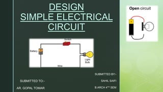
ARCHITECTURAL 4TH SEMESTER TOPIC, THATS HELPS IN UDERSTANDING OF ADHESIVES AND THERE USES, MARKET SRVEYS ARE THERE FROM INDIANMARTS THATS AVAILABLE ON INTERNET.
electrical luminaries and market surveysahil saifi
A luminaire is defined in Article 100 as “a complete lighting unit consisting of a lamp or lamps together with the parts designed to distribute the light, to position and protect the lamps and ballast (where applicable), and to connect the lamps to the power supply.” Since luminaires (lighting fixtures) were not previously defined before the 2002 NEC, this new definition is meant to cover all aspects of a lighting unit, including the lamps that actually provide the illumination, as well as internal and external parts necessary for the proper operation of the unit.
A primary school (in Ireland, the UK[1] & Australia[2]), junior school (in Australia[3][4]), elementary school or grade school (in the US & Canada) is a school for primary education of children who are four to eleven years of age (and sometimes up to thirteen years of age). It typically comes after preschool and before secondary school.
EASY TUTORIAL OF HOW TO USE CAPCUT BY: FEBLESS HERNANEFebless Hernane
CapCut is an easy-to-use video editing app perfect for beginners. To start, download and open CapCut on your phone. Tap "New Project" and select the videos or photos you want to edit. You can trim clips by dragging the edges, add text by tapping "Text," and include music by selecting "Audio." Enhance your video with filters and effects from the "Effects" menu. When you're happy with your video, tap the export button to save and share it. CapCut makes video editing simple and fun for everyone!
Explore the essential graphic design tools and software that can elevate your creative projects. Discover industry favorites and innovative solutions for stunning design results.
ARENA - Young adults in the workplace (Knight Moves).pdfKnight Moves
Presentations of Bavo Raeymaekers (Project lead youth unemployment at the City of Antwerp), Suzan Martens (Service designer at Knight Moves) and Adriaan De Keersmaeker (Community manager at Talk to C)
during the 'Arena • Young adults in the workplace' conference hosted by Knight Moves.
Technoblade The Legacy of a Minecraft Legend.Techno Merch
Technoblade, born Alex on June 1, 1999, was a legendary Minecraft YouTuber known for his sharp wit and exceptional PvP skills. Starting his channel in 2013, he gained nearly 11 million subscribers. His private battle with metastatic sarcoma ended in June 2022, but his enduring legacy continues to inspire millions.
Storytelling For The Web: Integrate Storytelling in your Design ProcessChiara Aliotta
In this slides I explain how I have used storytelling techniques to elevate websites and brands and create memorable user experiences. You can discover practical tips as I showcase the elements of good storytelling and its applied to some examples of diverse brands/projects..
PDF SubmissionDigital Marketing Institute in NoidaPoojaSaini954651
https://www.safalta.com/online-digital-marketing/advance-digital-marketing-training-in-noidaTop Digital Marketing Institute in Noida: Boost Your Career Fast
[3:29 am, 30/05/2024] +91 83818 43552: Safalta Digital Marketing Institute in Noida also provides advanced classes for individuals seeking to develop their expertise and skills in this field. These classes, led by industry experts with vast experience, focus on specific aspects of digital marketing such as advanced SEO strategies, sophisticated content creation techniques, and data-driven analytics.
2. z ELECTRICAL CIRCUITS
The electric circuits are closed-loop or path which forms
a network of electrical components, where electrons are
able to flow. This path is made using electrical wires
and is powered by a source, like a battery. The start of
the point from where the electrons start flowing is called
the source whereas the point where electrons leave the
electrical circuit is called the return
3. z
SIMPLE CIRCUIT
•Cell: It is the power source.
•Load: It is also termed as the resistor. It is a light bulb that lights when
the circuit is turned on.
•Conductors: They are made of copper wires with no insulation. One
end of the wire is connected the load to the power source and the other
end of the wire connects the power source back to the load
•Switch: It is a small gap in the circuit. There are various types of
switches. A switch can be used to open or close a circuit.
4. z
What is an electric current?
An electric current is a flow of microscopic particles called
electrons flowing through wires and components. current
flow from the Negative terminal to the Positive terminal of a
cell.
simple circuits
Here is a simple electric circuit. It has a cell, a lamp and a
switch. cell wires switch lamp To make the circuit, these
components are connected together with metal connecting
wires.
When the switch is closed, the lamp lights up. This is
because there is a continuous path of metal for the electric
current to flow around. If there were any breaks in the circuit,
the current could not flow.
6. z SIMPLE LIGHT CIRCUIT
A simple electrical circuit consists of a power source, two
conducting wires (one end of each being attached to each terminal
of the cell), and a small lamp to which the free ends of the wires
leading from the cell are attached.
SIMPLE FAN CIRCUIT
A simple electrical fan circuit consists of a power source,
two conducting wires (one end of each being attached to
each terminal of the cell), and a fan to which the free ends
of the wires leading from the cell are attached
7. z TYPES OF CIRCUIT
There are two types of electrical circuits
1. SERIES CIRCUITS
2. PARALLEL CIRCUITS
SERIES CIRCUITS
The components are connected end-to-end, one after the
other. They make a simple loop for the current to flow
round If one bulb ‘blows’ it breaks the whole circuit and all
the bulbs go out.
PARALLEL CIRCUITS
The components are connected side by side. The current
has a choice of routes. If one bulb ‘blows’ there is still be a
complete circuit to the other bulb so it stays alight.
9. z
Where we use series or parallel circuit
In a series circuit,
• every device must function for the circuit to be complete. If
one bulb burns out in a series circuit, the entire circuit is
broken. In parallel circuits, each light bulb has its
own circuit, so all but one light could be burned out, and the
last one will still function.
• All mains operated appliances have switches that are
connected to the live wire (the wire that carries current into
the appliance). When a switch is in series with a device, it
controls the device, allowing us to switch it on and off.
• For example, often lawnmowers have two switches in series
with each other so that both switches need to be pressed
before the mower will turn on.
10. z
Advantages of Series Connection
•Less size of wire cable is required in series wiring.
•We use to protect the circuit to connect fuse & circuit breakers in series
with other appliances.
•Series circuit don’t get overhead easily due to high resistance when more
load added in the circuit.
•The lifespan of battery in series circuit is more as compared to parallel.
•It is most simple method of electrical wiring and fault can be easily detect
and repair as compared to parallel or series-parallel wiring.
11. z
Parallel circuit:-
connection is very common in use. Various lamps and electrical
appliances in our homes are connected in parallel so that each
of the lamps or bobs and appliances can be operated
independently. For us to have control over the individual lamps or
loads, they have to be wired in parallel.
Advantages of Parallel Circuit
•Each connected electrical device and appliance are independent from others. This way, switching
ON / OFF a device won’t affect the other appliances and their operation.
•In case of break in the cable or removal of any lamp will not break the all circuits and connected
loads, in other words, other lights/lamps and electrical appliances will still work smoothly.
•If more lamps are added in the parallel lighting circuits, they will not be reduced in brightness (as it
happens only in series lightning circuits). Because voltage is same at each point in a parallel
circuit. In short, they get the same voltage as the source voltage.
•It is possible to add more light fixture and load points in parallel circuits according to future need
as far as the circuit is not overloaded.
•Adding additional devices and components wont increase the resistance but will decrease the
overall resistance of the circuit especially when high current rating devices are used such as air
conditioner and electric heaters.
•parallel wiring is more reliable, safe and simple to use.
12. z
Loop in system
A loop system, as the name implies, loops through the service
area and returns to the original point. The loop is usually tied into
an alternate power source. By placing switches in strategic
locations, the utility can supply power to the customer from either
direction.
13. zThe loop system provides better continuity of service than the radial
system, with only short interruptions for switching. In the event of
power failures due to faults on the line, the utility has only to find the
fault and switch around it to restore service. The fault itself can then
be repaired with a minimum of customer interruptions.
The loop system is more expensive than the radial because more
switches and conductors are required, but the resultant improved
system reliability is often worth the price.
14. z
JOINT BOX SYSTEM
An electrical junction box (also known as a ‘jbox’)
is an enclosure housing electrical
connections.[1] Junction boxes protect the electrical
connections from the weather, as well as prevent
people from accidental electric shocks.