Downloaded 27 times
![International Journal of Advances in Engineering & Technology, June, 2017.
©IJAET ISSN: 22311963
355 Vol. 10, Issue 3, pp. 354-364
II. LITERATURE REVIEW
Non-uniform Temperature Distribution in Electronic Devices Cooled by Flow in Parallel
Microchannels, was discussed by Hetsroni et al. [1]. Two-Phase Flow Patterns in Parallel
Microchannels was studied by Hetsroni et al. [2]. They analyzed the effect of geometry on flow and
heat transfer, finding that an increasingly uniform heat flux resulted in an increased irregularity of
temperature distribution on the chip surface.
Baud [3] conducted an optimization study to minimize the temperature gradient and the maximum
temperature for microchannel heat sink. It was demonstrated that further reduction in maximum
temperature and temperature gradient could be achieved by varying the cross-sectional dimensions of
the microchannel. The penalty of this method is the dramatically increased pressure drop due to the
acceleration along the flow direction.
Zhao and Lu [4] presented an analytical and numerical study on the heat transfer characteristics of
forced convection across a microchannel heat sink. Two analytical approaches are used by them: the
porous medium model and the fin approach. In the porous medium approach, the modified Darcy
equation for the fluid and the two-equation model for heat transfer between the solid and fluid phases
are employed. Firstly, the effects of channel aspect ratio and effective thermal conductivity ratio on
the overall Nusselt number of the heat sink are studied in detail. The predictions from the two
approaches both show that the overall Nusselt number increases as aspect ratio increased and
decreases with increasing thermal conductivity.
The effect of porosity on the thermal performance of the microchannel was also examined by them.
They found that, whereas the porous medium model predicts the existence of an optimal porosity for
the microchannel heat sink, the fin approach predicts that the heat transfer capability of the heat sink
increases monotonically with the porosity.
They also studied the effect of turbulent heat transfer within the microchannel, and they found that
turbulent heat transfer results in a decreased optimal porosity in comparison with that for the laminar
flow. They proposed a new concept of microchannel cooling in combination with micro heat pipes,
and the enhancement in heat transfer due to the heat pipes is estimated. Finally, they conducted two-
dimensional numerical calculations for both constant heat flux and constant wall temperature
conditions to check the accuracy of analytical solutions and to examine the effect of different
boundary conditions on the overall heat transfer.
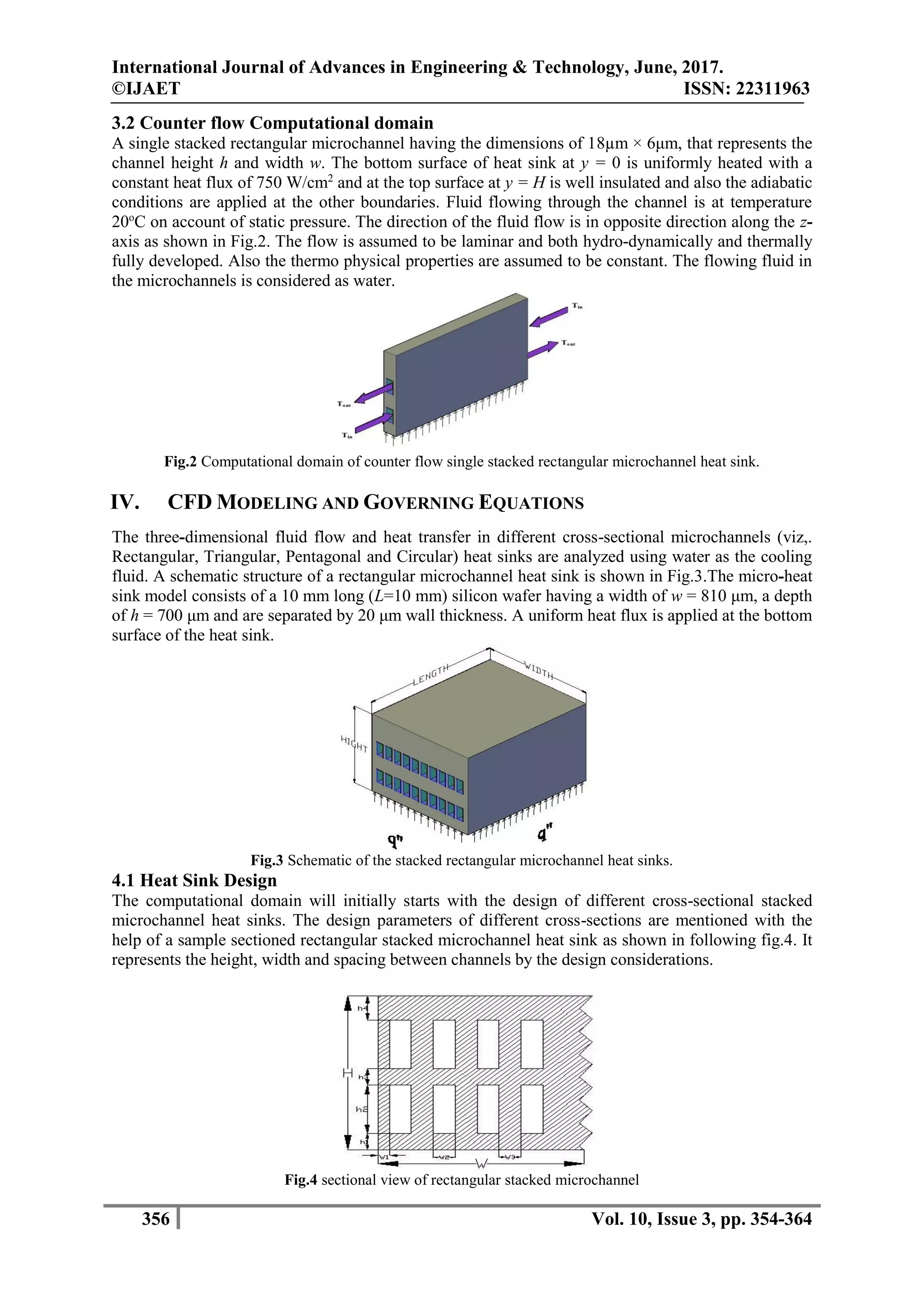
III. DESCRIPTION OF THE COMPUTATIONAL DOMAIN
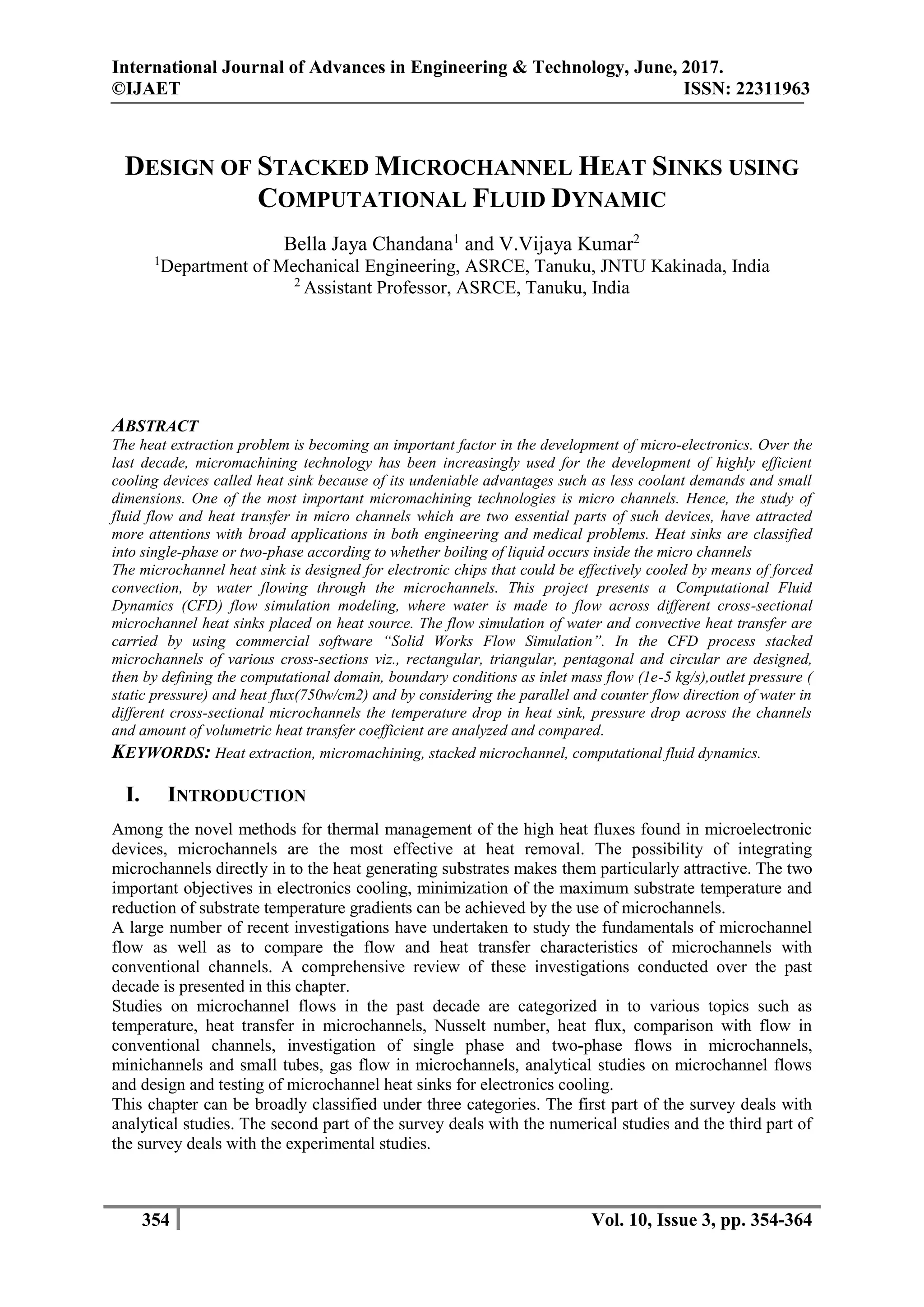
3.1 Parallel flow Computational domain
A single stacked rectangular microchannel having the dimensions of 18µm × 6μm, that represents the
channel height h and width w. The bottom surface of heat sink at y = 0 is uniformly heated with a
constant heat flux of 750 W/cm2
and at the top surface at y = H is well insulated and also the adiabatic
conditions are applied at the other boundaries. Fluid flowing through the channel is at temperature
20o
C on account of static pressure. The direction of the fluid flow is parallel to the z-axis as shown in
Fig.1. The flow is assumed to be laminar and both hydro-dynamically and thermally fully developed.
Also the thermo physical properties are assumed to be constant. The flowing fluid in the
microchannels is considered as water.
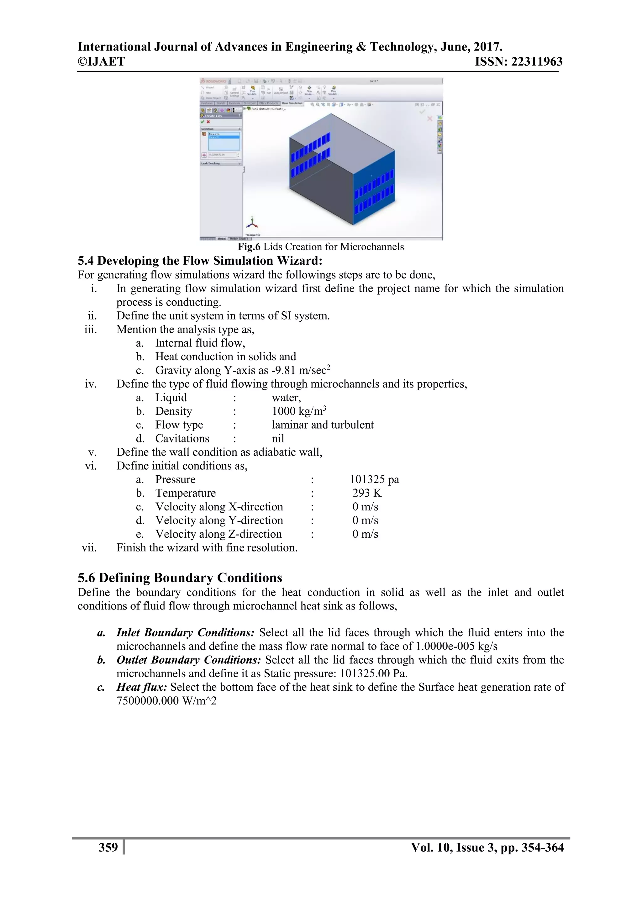
Fig.1: Computational domain of parallel flow single stacked rectangular microchannel heat sink](https://image.slidesharecdn.com/9i39-ijaet1003311-v10-i3-pp354-364-170719095937/75/DESIGN-OF-STACKED-MICROCHANNEL-HEAT-SINKS-USING-COMPUTATIONAL-FLUID-DYNAMIC-2-2048.jpg)
![International Journal of Advances in Engineering & Technology, June, 2017.
©IJAET ISSN: 22311963
363 Vol. 10, Issue 3, pp. 354-364
Table.6 Comparing Different Input Heat Flux
Design of channel Heat input (W/cm2
)
Thermal resistance
Rth Rpr
Rectangular 750 0.151 0.1413
Triangular 450 0.112 0.108
So from the above results we conclude that the results obtained from simulation are approximately
equal to theoretical results for rectangular microchannel.
VII. CONCLUSIONS
The fluid flow and heat transfer processes in a rectangular, triangular, pentagonal and circular micro-
channel heat sink with parallel and counter flow were analyzed by using “SOLID WORKS FLOW
SIMULATION” and obtained numerically base temperature of the heat sink, temperature rise in fluid,
pressure drop across micro channels and volumetric heat transfer coefficients.
Based on the analysis of the different cross-sectional stacked microchannel heat sink behaviour the
following conclusions can be drawn
From the results during the process of simulation it was observed that the base temperature of
the heat sink is having a minimum temperature of 250
C to maximum of 68.390
C for
rectangular microchannel heat sink when compared to other cross-sectional heat sinks.
From the numerical study on different micro-channel heat sinks (rectangular, triangular,
pentagonal and circular) by parallel and counter flow study we conclude that rectangular
microchannel heat sink will give better volumetric heat transfer coefficient 0.64 W/cm3
K in
counter flow when compared to other cross-sectional microchannel heat sinks.
From the results we can observe that, the temperature of fluid coming out from rectangular
microchannel in both parallel (45.60
C) and counter flows (60.610
C) are more when compared
to other cross-sectional microchannel heat sinks.
The heat transfer and fluid flow models used in the present study have been developed and
simulated using “SOLID WORKS FLOW SIMULATION” process, however to validate the
results we calculate the thermal resistances and are compared against experimental results.
ACKNOWLEDGEMENT
The author would like to thank all the persons who helped in the completion of his experimental
work. Also thanks are extended to ASR College of Engineering, Tanuku, and, INDIA for support
through the execution of the experimental work.
REFERENCES
[1]. Hetsroni, G., Mosyak, A. and Segal, Z., (2001), “Non-uniform temperature distribution in electronic
devices cooled by flow in parallel microchannels”, IEEE Transactions onComponents and Packaging
Technologies, Vol. 24, pp. 16-23.
[2]. Hetsroni, G., Mosyak, A., Segal, Z. and Pogrebnyak, E., (2003), “Two-phase flow patterns in parallel
microchannels”, International Journal of Multiphase Flow, Vol. 11, pp. 353-358.
[3]. Bau, H.H., (1998), “Optimization of conduits’ shape in micro heat exchangers”, International Journal
of Heat and Mass Transfer, Vol. 41, pp. 2717-2723.
[4]. Zhao, C.Y. and Lu, T.J., (2002), “Analysis of microchannel heat sinks for electronics cooling”,
International Journal of Heat and Mass Transfer, Vol. 45, pp. 4857-4869.
[5]. Harpole, G.M. and Eninger, J.E., (1991), “Microchannel heat exchanger optimization”, IEEE
Proceedings of the Seventh Semi-Thermo Symposium, Vol. 361, pp, 59-63.
[6]. Copeland, D., Behnia, D. and Nakayama, W., (1996), “Manifold microchannel heat sinks: Isothermal
analysis”, IEEE Proceedings of the Fifth Intersociety Conference onThermal Phenomena in Electronic
Systems, pp. 251-257.](https://image.slidesharecdn.com/9i39-ijaet1003311-v10-i3-pp354-364-170719095937/75/DESIGN-OF-STACKED-MICROCHANNEL-HEAT-SINKS-USING-COMPUTATIONAL-FLUID-DYNAMIC-10-2048.jpg)
![International Journal of Advances in Engineering & Technology, June, 2017.
©IJAET ISSN: 22311963
364 Vol. 10, Issue 3, pp. 354-364
[7]. Ng, E.Y.K. and Poh, S.T., (1999), “Investigative study of manifold microchannel heat sinks for
electronic cooling design”, Journal of Electronics Manufacturing, Vol. 9, pp. 155-166.
[8]. Hung, T.C., Wangi S.K. and Tsai, F.P., (1997), “Simulation of passively enhanced conjugate heat
transfer across an array of volumetric heat sources”, International Journalfor Numerical Methods in
Engineering, Vol. 13, pp. 855-866.
[9]. Li, J., Peterson, G.P. and Cheng, P., (2004), “Three-dimensional analysis of heat Transfer in a micro-
heat sink with single phase flow”, International Journal of Heat and MassTransfer, Vol. 47, pp. 4215-
4231.
[10]. Masud, Bebnia,,Wataru, Nakayama. and Jeffrey, Wan., (1998), “CFD simulations of heat transfer from
a heated module in an air Stream: comparison with experiments and a parametric study”, IEEE
Intersociety Conference on Thermal Phenomena, Vol. 54,pp.539-544.
[11]. Qu, W. and Mudawar, I., (2002), “Analysis of three-dimensional heat transfer in microchannel heat
sinks”, International Journal of Heat and Mass Transfer, Vol. 45, pp. 3973-3985.
[12]. Ryu, J.H., Choi, D.H. and Kim, S.J., (2003), “Three-dimensional numerical optimization of a manifold
microchannel heat sink”, International Journal of Heat and Mass Transfer, Vol. 46, pp. 1553-1562.
AUTHORS BIOGRAPHY
Bella Jaya Chandana was born in Polavaram, Andhrapradesh, India, in 1991. He receive
the bachelor‘s degree in mechanical engineering from the university of Jawaharlal Nehru
technological university, Kakinada, in 2013. He is currently pursuing the master degree in
thermal engineering from the university of Jawaharlal Nehru technological university,
Kakinada. His research interests include Design of Stacked Microchannel Heat Sinks Using
Computational Fluid Dynamic.](https://image.slidesharecdn.com/9i39-ijaet1003311-v10-i3-pp354-364-170719095937/75/DESIGN-OF-STACKED-MICROCHANNEL-HEAT-SINKS-USING-COMPUTATIONAL-FLUID-DYNAMIC-11-2048.jpg)

The document discusses the design and CFD analysis of stacked microchannel heat sinks aimed at improving cooling efficiency for microelectronic devices. It presents a study that utilizes computational fluid dynamics software to simulate fluid flow and heat transfer in various cross-section designs, including rectangular, triangular, pentagonal, and circular channels. The results indicate varying performance in temperature and pressure drops, revealing the effectiveness of microchannels in thermal management.


