Download to read offline
![International Research Journal of Engineering and Technology (IRJET) e-ISSN: 2395-0056
Volume: 06 Issue: 11 | Nov 2019 www.irjet.net p-ISSN: 2395-0072
© 2019, IRJET | Impact Factor value: 7.34 | ISO 9001:2008 Certified Journal | Page 2200
THERMAL ANALYSIS OF CORRUGATED PLATE HEAT EXCHANGER BY
USING ANSYS SOFTWARE THROUGH FEA METHOD
Moh Shahid Khan1, Animesh Singhai2
1MTech Scholar, Department of Mechanical Engineering, TITR, Bhopal, India
2Professor, Department of Mechanical Engineering, TITR, Bhopal, India
---------------------------------------------------------------------***----------------------------------------------------------------------
Abstract –The effects of nanofluid that is Al2O3 in waterin
a counter flow corrugated plate heat exchanger were
investigated through an experiment by Shive Dayal Pandey
and V. K. Nema. It had been discovered that the heat transfer
characteristics improve with the decrease in nanofluid
concentration. Power consumption and heat transfer rates
were lower for water compared to the nanofluid. For a given
heat load the nanofluid needed the lower rate of flow,
however, suffered a higher pressure drop than that for water.
For a given pumping power additional heat mightberemoved
by the nanofluids relative to water, though the most heat
transfer rate was found with very cheap concentration of
nanofluids. Correlation equations were obtained for the
Nusselt number and the Friction factor for both water andthe
nanofluid. N. Putra, W. Roetzel and S.K. Das showed that
natural convection heat transfer by applying nanofluid of
Al2O3/water and CuO/water was not up to the mark as
compared to the base fluid. Also, they found that this might
result in too many factors like the sinkingof nanoparticlesand
speed distinction between nanoparticles and base fluid.
Considering these facts, I concluded that becauseofadditional
drop-in pressure just in case of nanofluid, there is additional
pumping power needed thus in place of nanofluid solelywater
is being thought-about for experiment. There is a passive
methodology to extend the heat transfer by increasing the
amount of heat transfer thatistestedherethroughANSYSFEA
methodology. Corrugated plate heat exchanger with the
counterflow has been studied along with the arrangement of
the hot fluid (water) on either side of the cold fluid channelfor
various volume flow rates of the cold fluid (water) along with
30-degree of corrugation angle and 20-degree of corrugation
angle. The setup was run through ANSYS Fluent and the
reports were observed and compared for the optimumresults.
Key Words: Heat Exchanger, Nanofluid, Heat Transfer,
Thermal Energy, Effectiveness,PassiveMethods,Corrugated
Plate.
1. INTRODUCTION
Heat exchanger is a device which is used to transfer
heat between two fluids at different temperature either by
direct contact or indirect contact with the help of a
separating wall made up of a highly conductive material.
These are widely used in various industries, vehicles,
engines etc and domestic applications as well. Global
warming is a phenomenon which has made us realize the
need for optimum usage of everything that we have. Every
researcher is putting their efforts in the field of energy-
saving and finding some ways that we can follow to make it
reality. Utilizing thermal energy in an efficientmanneris our
prime focus here. Heat exchangers have already been one of
the most talked topics among the researchers so a lot of
work has been done in this field already and this research
work is also aimed to acknowledge their efforts in this field.
There are two ways to improve the rate of heat
transfer by active methods and passive methods. Active
methods need someenergyinputtoachievehigher efficiency
and it has limitations to do it whereas passive methods don’t
need any energy input so researchers are more concerned
about these methods. It has also many constraints but still
lots of scope to achieve higher efficiency for heat exchanging
process. Technical constraints which are responsible forthe
improvement in the rate of heat transfer are surface area
and overall heat transfer coefficient. Ourfocusistostudythe
relations and key features which can improve the rate of
heat transfer by improving the heat transfer coefficient.
2. Literature Survey
The performance of heat exchangers may be
improved by heat transfer improvement techniques for
playing a particular heat-transfer duty. Improvement of the
heat transfer allows the scale of the heat exchanger to be
considerably shrunken. Many researchers have done their
experiments and analysis over the factors which are
responsible for improvement of heat transfer rate and the
same has been discussed and reviewed here in this section.
Fluids, like water and engine oil, have poor heat
transfer performance and so, high compactness and
effectiveness of heat transfer systems are necessary to
realize the desired heat transfer. Among the efforts for
improvement of heat transfer, the applying of additives to
liquids is critical [1,2]. The word nanofluid can bedefined as
a suspension of nano-sized solid particles in typical fluids;
such fluids embrace increased heat transfer characteristics,
like convective heat transfer. This hefty increase in heat
transfer could result in remittent energy expenditure and
raw material-input, also reduces the size of the apparatus
and consequently reduces expenses and exaggeratessystem
potency.](https://image.slidesharecdn.com/irjet-v6i11261-200128062808/75/IRJET-Thermal-Analysis-of-Corrugated-Plate-Heat-Exchanger-by-using-Ansys-Software-through-FEA-Method-1-2048.jpg)
![International Research Journal of Engineering and Technology (IRJET) e-ISSN: 2395-0056
Volume: 06 Issue: 11 | Nov 2019 www.irjet.net p-ISSN: 2395-0072
© 2019, IRJET | Impact Factor value: 7.34 | ISO 9001:2008 Certified Journal | Page 2201
Primarily Choi [3] used the nanometer-sized
particles in the typical fluids and showed improvement in
heat transfer characteristics.
The majority of experimental studies on the
applying of nanofluidsatsingle-phaseforcedconvectiveheat
transfer are involved with streamline flow principally in
outwardly heated circular tubes or micro-channels. Among
the varied sorts of nanofluids used, metal oxideswithpartial
volume concentrations are the foremost common, most
likely because of their cheaper price [4].
Studies on heat transfer of suspension of metal
oxides in fluids were restricted to suspensions with
millimeter or micron-sized particles. Such giant particles
could cause severe issues in heat transfer instrumentation.
specifically, giant particles tend to quickly settle out of
suspension and thereby passing through micro channels
causes severe wearing and increase the pressure drop
significantly [5].
Experimental investigation performed on the
suspension of 4 percentage volume & 35 nm sized particles
of CuO in ethylene glycol resulted in high improvement in
the thermal physical phenomenon [6].
The investigation of 35 nm-sized Cu/deionized
water nanofluid flowing during a tube with constant wall
heat flux showed the improvement in Nusselt number
compared to pure water for identical rate of flow by
increasing the volume fractionofnanoparticlesfrom0.5% to
1.2% [7].
In another study, Al2O3/water nanofluid heat
transfer in streamline flow underneath constant wall heat
flux and reported a rise in the nanofluid heat transfer
constant with Reynold’s number and nanoparticle
concentration significantly within the entrance region in
which thermal developing length for nanofluid was larger
than in case of pure water. Wen and dingdong [8].
The numerical investigation for heat transfer of
Al2O3/ethylene glycol and Al2O3/waternanofluidsduringa
radial flow system showed improvement in heat transfer
rate. Conjointly, researchers showed that wall shear stress
improved with concentration and Reynold’s number [9].
It had been reported by Putra et al. [10], that
natural convection heat transfer by applying nanofluid of
Al2O3/water and CuO/water was not up to the mark as
compared to the base fluid and all over that this might result
in too many factors like the sinking of nanoparticles and
speed distinction between nanoparticles and base fluid.
Thermo-physical properties of CuO nanofluid were
measured and investigatedtheperformanceofnanofluid and
compared it to the base fluid (i.e., water) by Pantzali et al.
[11].
The performance of a nanofluid containing carbon
nanotubes resulted in improvement of the heat transfer
which was observed as 3.5 times higher than the base fluid,
which was studied by Ding et al. [12].
Experimentation withAl2O3 andTiO2asnanofluids
along with a shell and tube exchanging device [13] has
shown that there's anoptimumvolumeconcentrationfor the
maximum value of overall heat transfer coefficient. This
optimum value of concentration differs fluid to fluid.
Thermo-physical properties are altered by the
addition of nanoparticles, and fluid viscosity and the nature
of flow, are the crucial parameters for determining the
effectualness of nanofluid [14].
Further, the heat transfer rate and heat transfer
constant during a PHE are above those use base fluid [15].
The work on two nanofluids specifically, Al2O3/EG
and CuO/EG having concentrations 0.1, 0.5, and 1 percent
respectively [16] have shown that theheattransferconstant
or coefficient will increase with temperature and
concentration each.
Al2O3/water of 6 volume percentageconcentration
in a fluid with Reynold’s number greater than 100 but lesser
than 500, temperature greaterthan20˚Cbutlesserthan40˚C
resulted that the performance of the PHE at a given rate of
flow didn't improve with the fluid [17].
Shive Dayal Pandey,V.K. Nema[18]:Theeffectsof
nanofluid that is Al2O3 in water two, three and four vol.%
and water as coolants on heat transfer,resistancelosses,and
loss of available energy during a counter flow corrugated
plate device were by experimentation investigated. The
desired properties of the nanofluid were measured. It had
been determined that the heat transfer characteristics
improve with the increase in Reynolds- and Peclet-number
and with the decrease in nanofluid concentration. For a
given heat load, the desired pumping power exaggerated
with the increase in nanofluid concentration. Each power
consumption and heat transferrateswerelowerforwater as
compared to the nanofluid for flow rates of 2–5 LPM for hot
and cold fluids. Further, for a given heat load the nanofluid
needed a lower rate of flow however suffered a higher
pressure drop than that for water.
3. Observations
Shive Dayal Pandey andV.K. Nema improvedrateof
heat transfer by using Nano Fluid (Al2O3 in Water) but
having more pressure drop consequently more power
consumption and more wear friction factor.
N. Putra, W. and Roetzel, S.K. Das showed that
natural convection heat transfer by applying nanofluid of
Al2O3/water and CuO/water was not up to the mark as
compared to the base fluid.](https://image.slidesharecdn.com/irjet-v6i11261-200128062808/75/IRJET-Thermal-Analysis-of-Corrugated-Plate-Heat-Exchanger-by-using-Ansys-Software-through-FEA-Method-2-2048.jpg)
![International Research Journal of Engineering and Technology (IRJET) e-ISSN: 2395-0056
Volume: 06 Issue: 11 | Nov 2019 www.irjet.net p-ISSN: 2395-0072
© 2019, IRJET | Impact Factor value: 7.34 | ISO 9001:2008 Certified Journal | Page 2202
Also, this might result in too many factors like the
sinking of nanoparticles and speed distinction between
nanoparticles and base fluid.
Mainly researches on heat transfer coefficients are
found for an unvarying wall temperature or an unvarying
heat flux. The condition of constant wall temperature is
idealized in heat exchangers with natural action like
condensers. The boundary condition of constant heat flux
finds application in electricallyheatedtubesandnuclearfuel
components. However, the case of liquid-liquid heat
exchange has not been studied well. In case the use of
nanofluid for increasing the heat transfer rate by
enhancement of the thermal conductivity of fluid has given
better result, but when observed closely then found that
there is more drop in fluid pressure from the inlet to outlet
that means there is greater resistancetoflowduetoincrease
in friction which will damage thewallsoftheheatexchanger,
so in the long term it will not be good enough where we need
to keep our system wear less also. In current work fluid to
fluid heat exchange is taken into thought and analysed.
Overall heat transfer coefficient is taken into consideration
based on the ANSYS result and our calculation. ANSYS
results were used to determine effectiveness, overall heat
transfer coefficient, and also LMTD for counter flow Heat
Exchanger. Results are compared and validated by the CFD
analysis of the same with the help of ANSYS Fluent software
between nanofluid and water with the changingcorrugation
angle as 30 degrees and 20 degrees.
3. Highlights
Collected the CFD data pertaining to heat transfer
and fluid flow in a corrugated plate heat exchanger
with different corrugation angle.
Flow rate of Cold Fluid varies from 2 to 5 LPM
Constant flow rate of Hot Fluid 2 LPM
Counter Flow arrangement of fluid flow
Cold Fluid flowing through the inner channel and
Hot Fluid flowing through the annulus
Once Corrugation Angle kept 30Degreeandthen20
Degree
4. Methodology
This lesson deals with the process methodology for
calculating effectiveness, LMTD and overall heat transfer
coefficient formulas used in calculation given in this part.
Mathematical calculation and value gained for Corrugated
Steel Plate counterflow, with corrugation angle of 30 degree
and 20 degree have been discussed here in this lesson. The
present work is to identify the effect of corrugated plate in
place of simple plane steel plate forheattransfer withsimple
water, not with nanofluid which was used for heat transfer
by Shive Dayal Pandey, V.K. Nema [18] to increase thermal
conductivity. And then we will compare the results of
nanofluid and water in counter-flow heat exchanger.
Fig 4.1 Methodology Flow Chart
The complete methodologyincludessomestepswhichareas
follows.
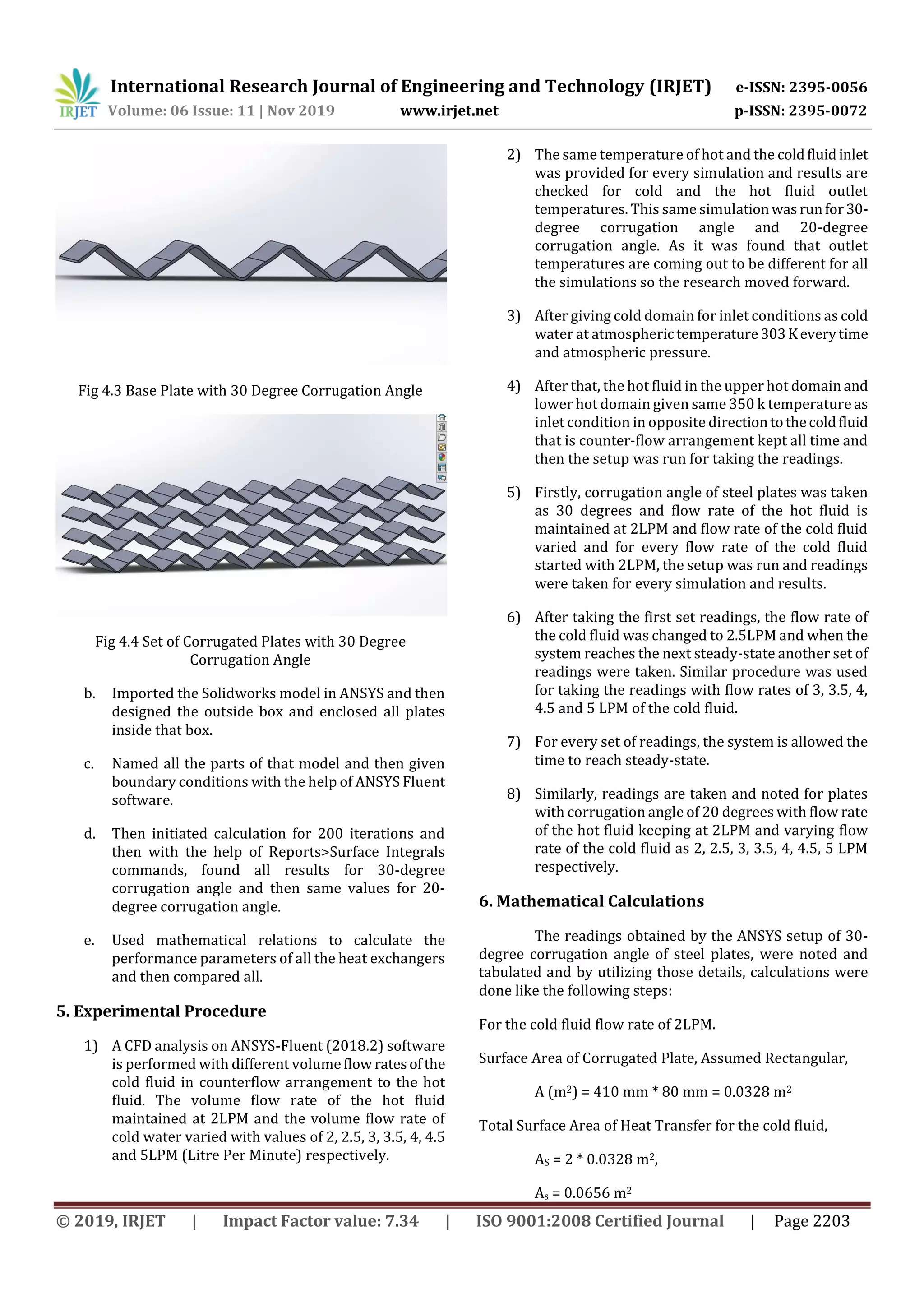
a. Designing 4 corrugated plates of 30-degree
corrugation angle and 20-degree corrugation angle
having plate thickness 1mm and 20 mm apart from
each other, with the help of Solidworks Designing
Software.
SN Parameter Value
1 Length of the test section L 350 mm
2 Width of the test section W 80 mm
3 Gap between two corrugated plates H 20 mm
4 Total height of the test section 120 mm
5 Developed length of the corrugated plate 410 mm
6 Corrugation angle 30
Table 4.1 Design Parameters of Corrugated Plate Heat Exchanger
Fig 4.2 20-Degree Corrugation Angle](https://image.slidesharecdn.com/irjet-v6i11261-200128062808/75/IRJET-Thermal-Analysis-of-Corrugated-Plate-Heat-Exchanger-by-using-Ansys-Software-through-FEA-Method-3-2048.jpg)
![International Research Journal of Engineering and Technology (IRJET) e-ISSN: 2395-0056
Volume: 06 Issue: 11 | Nov 2019 www.irjet.net p-ISSN: 2395-0072
© 2019, IRJET | Impact Factor value: 7.34 | ISO 9001:2008 Certified Journal | Page 2204
Total Heat Transfer Rate, Q(W)fromWall ColdDomainPlate
2 Shadow = Heat Flux * Area
= 8007.904 * 0.0328
= 262.6592512 W
Total Heat Transfer Rate, Q(W)fromWall ColdDomainPlate
3 Shadow = Heat Flux * Area
= 8044.5772* 0.0328
= 263.86213216 W
Total rate of heat transfer to the cold fluid,
Q = 262.6592 + 263.8621 = 526.52138336 W
Wall Temperature for Wall Cold Domain Plate 2 Shadow,
Ts = 326.31457 k
Wall Temperature for Wall Cold Domain Plate 3 Shadow,
Ts = 326.40516 k
Bulk Mean Temperature,
Tb = Average of (Temperature of the cold fluid Inlet &
Temperature of the cold fluid Outlet)
Tb = Avg (Tci, Tce) = (303 + 307.1526) ÷ 2 = 305.07633 k
Temperature Difference (dT= Ts – Tb) for Wall Cold Domain
Plate 2 Shadow = 326.31457 – 305.07633
= 21.23824 k
Similarly,
dT for Wall Cold Domain Plate 3 Shadow = 21.32883 k
∆Ti (Counter Flow) = Thi – Tce
= 350 – 307.15266
= 42.84734 k
∆Te (Counter Flow) = The – Tci
= 347.64229 – 303
= 44.64229 k
Logarithmic Mean Temperature Difference (LMTD),
θm = = 43.7386 k
Heat Capacity, for the cold fluid,
mC = 0.033333333 kg/s * 4187 j/kg.k
= 139.5666667
Heat Capacity, for the cold fluid,
mC = 0.033333333 kg/s * 4187 j/kg.k
= 139.5666667
Heat Transfer Rate (Q),
Q = mC * (Tce – Tci)
= 139.5666667 * (307.15266 – 303)
= 579.572914 W
Overall Heat Transfer Coefficient (U),
U = Q/(As*θm ) Watts/m2k
∆Tmax = Thi – Tci = 47 k
Maximum Heat Transfer Rate (Qmax),
Qmax = mCmin * ∆Tmax W
= 6559.633333 W
Effectiveness (∈),
∈ = Q/Qmax
= 0.088354468
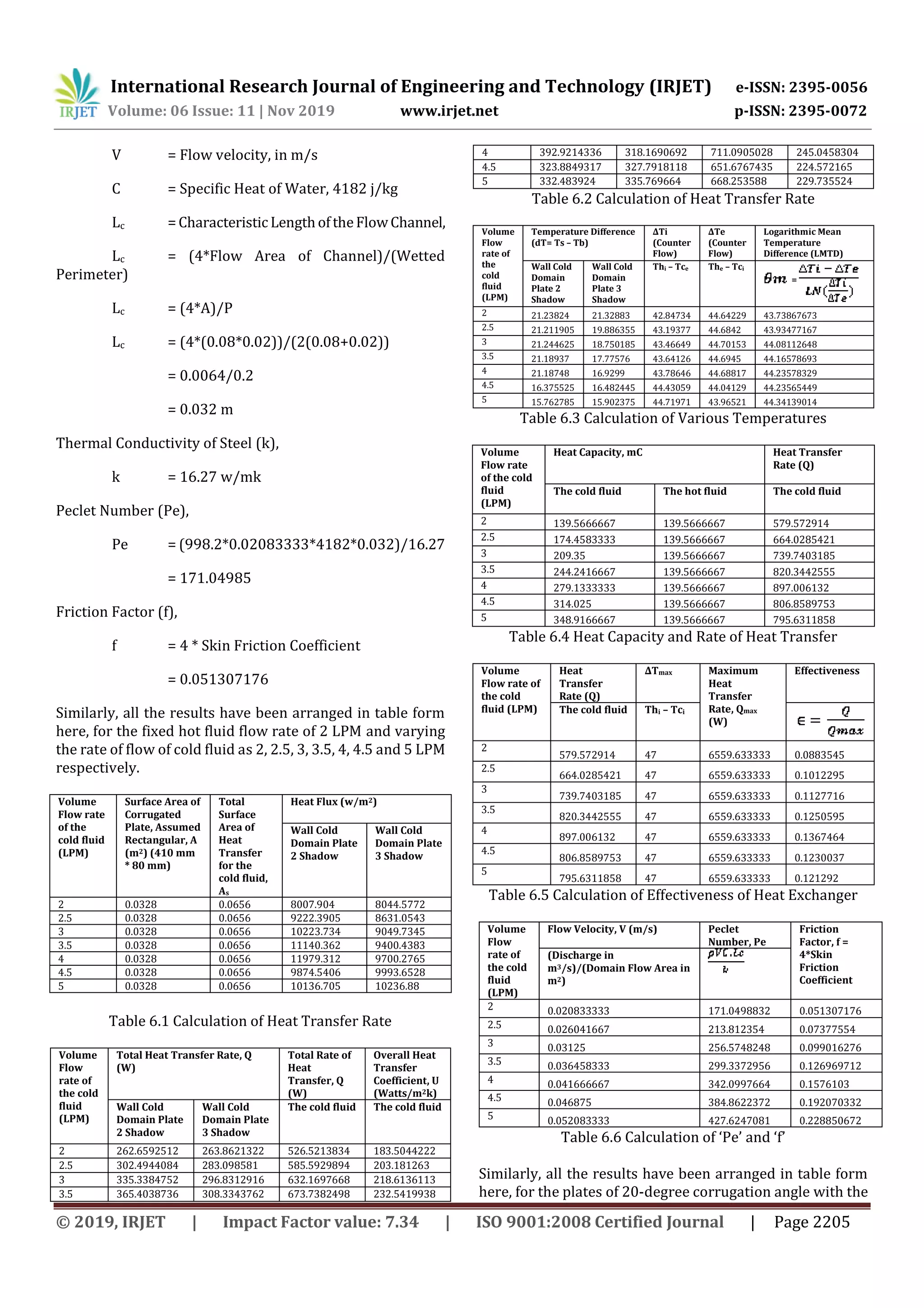
Flow Velocity (V),
V = (Discharge in m3/s)/(Domain Flow Area
in m2)
= 0.0000333333/(0.08*0.02)
= 0.020833333 m/s
Peclet Number (Pe),
Pe = Re * Pr
= [ρVLc/μ] * [μC/k]
= ρVC.Lc/k
Where,
Re = ρVLc/μ (Reynold’s Number)
Pr = μC/k (Prandtl Number)
ρ = density of water,
= 998.2 kg/m3 (from Ansys)](https://image.slidesharecdn.com/irjet-v6i11261-200128062808/75/IRJET-Thermal-Analysis-of-Corrugated-Plate-Heat-Exchanger-by-using-Ansys-Software-through-FEA-Method-5-2048.jpg)

![International Research Journal of Engineering and Technology (IRJET) e-ISSN: 2395-0056
Volume: 06 Issue: 11 | Nov 2019 www.irjet.net p-ISSN: 2395-0072
© 2019, IRJET | Impact Factor value: 7.34 | ISO 9001:2008 Certified Journal | Page 2209
Effectiveness of heat exchanger is showing growth
with 30-degree corrugation angle and highest effectiveness
at coolant flow rate of 4 LPM.
SN
Volume Flow Rate
of the cold fluid
(LPM)
LMTD for 30 Degree
Corrugation Angle
LMTD for 20 Degree
Corrugation Angle
1 2 43.73867673 43.9819338
2 2.5 43.93477167 44.18849607
3 3 44.08112648 43.92077162
4 3.5 44.16578693 44.0836771
5 4 44.23578329 44.15711377
6 4.5 44.23565449 44.21328625
7 5 44.34139014 44.40994055
Table 7.9 Variation of LMTD with Coolant Flow Rate
Fig 7.9 Variation of LMTD with Coolant Flow Rate
20-degree corrugation angle is showing zig zag
trend in LMTD (Logarithmic Mean Temperature Difference)
with coolant flow rate whereas 30-degree corrugationangle
is showing steady growth rate with a little dropat4.5LPM of
coolant flow rate. For the optimum result from 3 LPM to 4.5
LPM, 30-degree corrugation angle should be preferred
whereas for highest value of LMTD, 20-degree corrugation
angle with 5 LPM of coolant flow rate should be preferred.
8. CONCLUSIONS
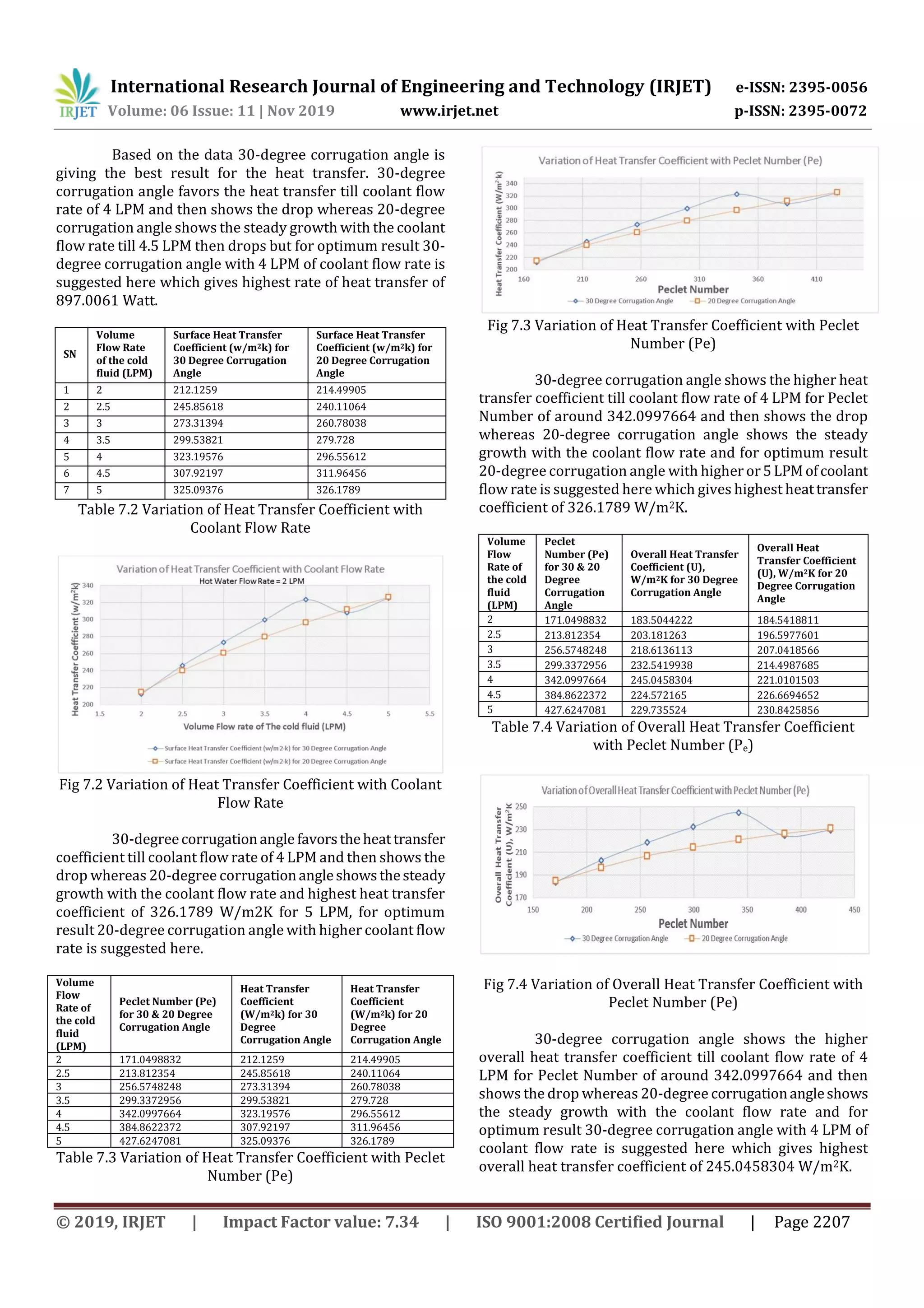
It has been observed in above study that 30-degree
corrugation angle with 4 LPM of coolant flow rate gives
highest rate of heat transfer of 897.0061 Watt, 20-degree
corrugation angle shows the steady growth with the coolant
flow rate and gives highest heat transfer coefficient of
326.1789 W/m2K for 5 LPM, and for the optimum result20-
degree corrugation angle with higher coolant flow rate is
suggested here. Where 20-degree corrugation angle with
higher or 5 LPM of coolant flow rate is suggested here which
gives highest heat transfer coefficient of 326.1789 W/m2K.
On in other hand 30-degree corrugation angle with
4 LPM of coolant flow rate is suggested here which gives
highest overall heat transfer coefficient of 245.0458304
W/m2K.
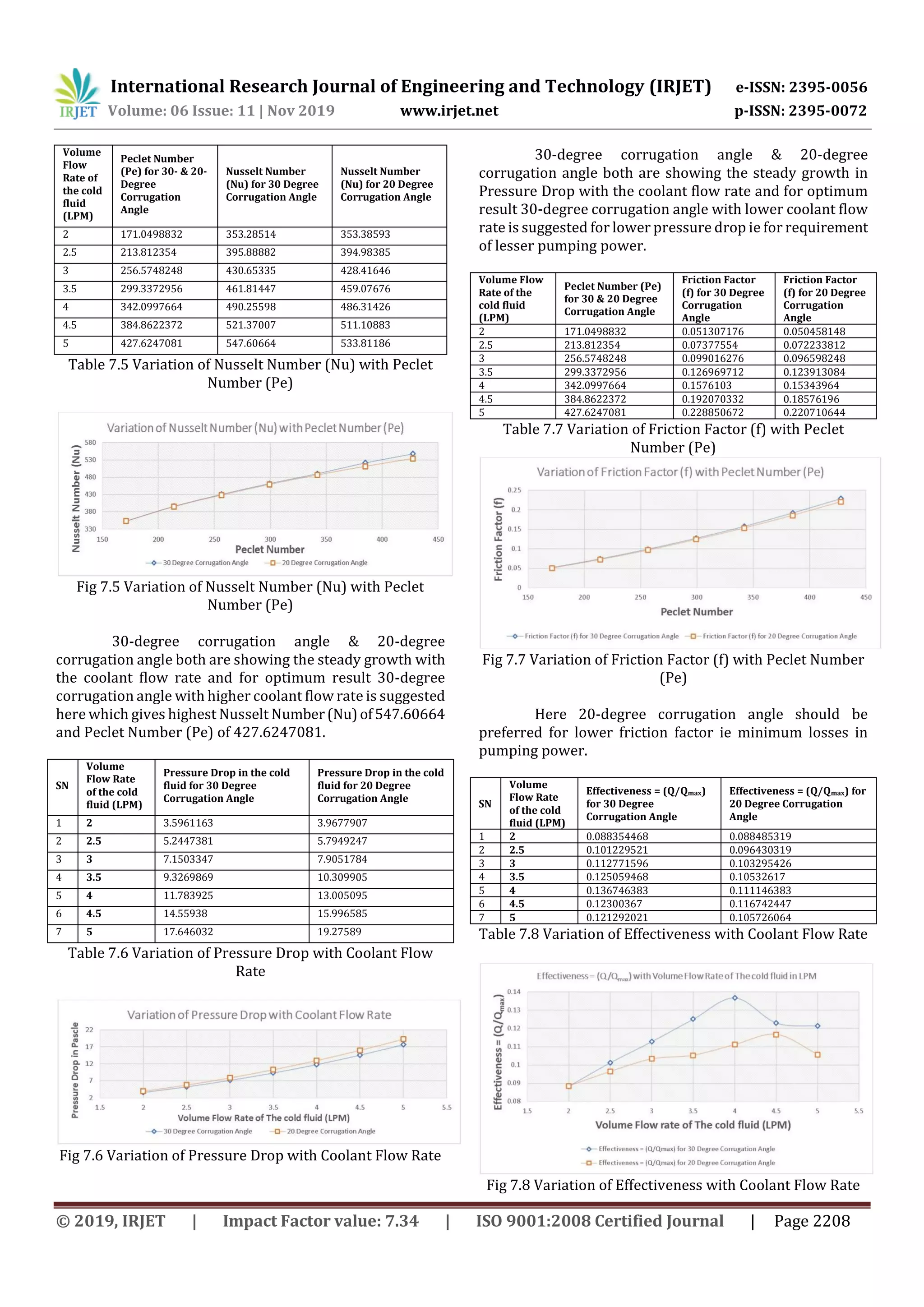
Results show that 30-degree corrugationangle with
higher coolant flow rate gives highest Nusselt Number (Nu)
of 547.60664 and Peclet Number (Pe) of 427.6247081.
Whereas 30-degree corrugation angle with lower
coolant flow rate gives lower pressure drop that is for
requirement of lesser pumping power 30-degree of
corrugation angle would be better to prefer. In another
perspective20-degreecorrugationangleshouldbepreferred
for lower friction factor that is minimum losses in pumping
power.
Effectiveness of heat exchanger is showing growth
with 30-degree corrugation angle and we get highest
effectiveness at coolant flow rate of 4 LPM. For the optimum
result of LMTD, from 3 LPM to 4.5 LPM, 30-degree
corrugation angle should be preferred whereas for the
highest value of LMTD, 20-degree corrugation angle with 5
LPM of coolant flow rate should be preferred.
Results for pressure drop were compared with the
experimental results obtained in the research work of S.D.
Pandey, V.K. Nema [18]. We found that in our research work
that pressure drop for 2 LPM volume flow rate of the cold
fluid and hot fluid was obtained as 3.59 to 3.96 Pa with the
total range of pressure drop as 3.59 Pa to 19.27 Pa whereas
in case of experiment with nanofluid[18]itsrangewas12Pa
to 160 Pa. We know that the pressure drop is responsiblefor
the consumption of power, so in place of using nanofluid,
only water could be used for better results along with the
passive way to improve the rate of heat transfer that is by
improving the area of heat transfer and changing the
corrugation angle of sheet.
8. Future Scope
It has been observed that still whole surface of corrugated
plate is not being used for the heat transfer by observing the
stream lines which are not completely in contact with
corrugated steel plates and to avoid this,onecanalsochange
angle of corrugation as 25-degree, 40-degree, 45-degree or
50-degree for corrugated plates. One can also take the
corrugation profile as pure Sine Curve and then compare
with the results of different angles. In this research work as
we have found all the results for various coolant flow rates
by keeping the the hot fluid flow rate constant as 2 LPM, so
there is scope for variation in the hot fluid flow rate for
better results. If the corrugated plate material is changed as
copper then due to more thermal conductivitythanthesteel,
there would be greater rate of heat transfer and also the
effectiveness will be higher.
REFERENCES
[1] A.E. Bergles, Recent development in convective heat
transfer augmentation, Appl. Mech.Rev.26(1973)675–682.
[2] A.S. Ahuja, Augmentation of heat transport in laminar
flow of polystyrene suspension: I. Experimental and results,
J. Appl. Phys. 46 (8) (1975) 3408– 3416.
[3] S.U.S. Choi, Developments and Application of Non-
Newtonian Flows, vol. 66, ASME FED V.231/ MD-V, New
York, 1995, pp. 99–105.](https://image.slidesharecdn.com/irjet-v6i11261-200128062808/75/IRJET-Thermal-Analysis-of-Corrugated-Plate-Heat-Exchanger-by-using-Ansys-Software-through-FEA-Method-10-2048.jpg)
![International Research Journal of Engineering and Technology (IRJET) e-ISSN: 2395-0056
Volume: 06 Issue: 11 | Nov 2019 www.irjet.net p-ISSN: 2395-0072
© 2019, IRJET | Impact Factor value: 7.34 | ISO 9001:2008 Certified Journal | Page 2210
[4] Xiang-Qi Wang, A.S. Mujumdar, Heat transfer
characteristics of nanofluids: a review, Int. J. Therm. Sci. 46
(2007) 1–19.
[5] S. Zeinali Heris, M. Nasr Esfahany, S.Gh. Etemad,
Numerical investigationofnanofluidlaminarconvectiveheat
transfer through circular tube, J. Numer. Heat Transfer, Part
A: Appl. 52 (2007) 1043–1058.
[6] S. Lee, S.U.S. Choi, S. Li, J.A. Eastman, Measuring thermal
conductivity of fluids containing oxide nanoparticles, J. Heat
Transfer 121 (1999) 280–289.
[7] Y. Xuan, Q. Li, Heat transfer enhancement of nanofluids,
Int. J. Heat Fluid Flow 21 (2000) 58–64.
[8] D. Wen, Y. Ding, Experimental investigation into
convective heat transfer of nanofluids at the entranceregion
under laminar flow conditions, Int. J. Heat Mass Transfer 47
(2004) 5181–5188.
[9] S.J. Palm, G. Roy, C.T. Nguyen, Heat transferenhancement
in a radial flow cooling system using nanofluids, in:
Proceeding of the ICHMT Inter. Symp. Advance Comp. Heat
Transfer, Norway, CHT-04-121, 2004.
[10] N. Putra, W. Roetzel, S.K. Das, Natural convection of
nanofluids, Heat Mass Transfer 39 (8) (2003) 775–784.
[11] M.N. Pantzali, A.G. Kanaris, K.D. Antoniadis, A.A. Mouza,
S.V. Paras, Effect of nanofluids on the performance of a
miniature plate heat exchanger with modulated surface, Int.
J. Heat Fluid Flow 30 (2009) 691–699.
[12] Y. Ding, H. Alias, D. Wen, R.A. Williams, Heat transfer of
aqueous suspensions of carbonnanotubes(CNTnanofluids),
Int. J. Heat Mass Transfer 49 (1–2) (2006) 240–245.
[13] B. Farajollahi, S.Gh. Etemad, M. Hojjat, Heat transfer of
nanofluids in a shell and tube heat exchanger, Int. J. Heat
Mass Transfer 53 (2010) 12–17.
[14] M.N. Pantzali, A.A. Mouza, S.V. Paras, Investigating the
efficacy of nanofluids as coolants in plate heat exchangers
(PHE), Chem. Eng. Sci. 64 (14) (2009) 3290– 3300.
[15] M.H. Fard, M.R. Talaie, S. Nasr, Numerical and
experimental investigation of heat transfer of ZnO/water
nanofluid in the concentric tube and plate heat exchangers,
Therm. Sci. 15 (1) (2011) 183–194.
[16] A. Zamzamian, S.N. Oskouie, A. Doosthoseini, A. Joneidi,
M. Pazouki, Experimental investigation of forced convective
heat transfer coefficient in nanofluids of Al(2)O(3)/EG and
CuO/EG in a double pipe and plate heat exchangers under
turbulent flow, Exp. Therm. Fluid Sci. 35 (3) (2011) 495–
502.
[17] Y.H. Kwon, D. Kim, C.G. Li, J.K. Lee, D.S. Hong, J.G. Lee,
S.H. Lee, Y.H. Cho, S.H. Kim, Heat transfer and pressure drop
characteristics of nanofluids in a plate heat exchanger, J.
Nanosci. Nanotechnol. 11 (7) (2011) 5769–5774.
[18] S.D. Pandey, V.K. Nema, Experimental analysis of heat
transfer and friction factor of nanofluid as a coolant in a
corrugated plate heat exchanger, Experimental Thermal and
Fluid Science 38 (2012) 248–256.](https://image.slidesharecdn.com/irjet-v6i11261-200128062808/75/IRJET-Thermal-Analysis-of-Corrugated-Plate-Heat-Exchanger-by-using-Ansys-Software-through-FEA-Method-11-2048.jpg)

This document discusses thermal analysis of a corrugated plate heat exchanger using ANSYS software through finite element analysis. It summarizes previous research on using nanofluids like Al2O3 in water to improve heat transfer in these types of heat exchangers. The document then outlines the methodology that will be used, which involves studying the corrugated plate heat exchanger with counterflow configuration and varying parameters like volume flow rate and corrugation angle to determine the optimal heat transfer results.


