This document discusses promising methods for laptop cooling using MEMS devices. It summarizes three primary MEMS cooling technologies: 1) Impinging jets, where micro-jets of air or fluid are used to directly cool hot surfaces through high-velocity impingement. 2) Heat exchangers and sinks, such as a closed-loop liquid cooling system with a microheat exchanger to efficiently transfer heat from circulating liquid. 3) Liquid cooling systems, though these take up more space than is suitable for laptops with current liquid cooling system designs. The document analyzes various studies on optimizing these approaches through nozzle design, array configurations, and microstructure engineering to maximize heat transfer rates while minimizing pressure drops and device sizes.
![Tyler Baker
6616
ME 141A
Promising Methods of Heat Dissipation for Laptops using MEMS Devices
Introduction
One of the biggest obstacles of designing compact electronics is dissipating the heat that
builds up within them. As laptop technologies advance, there is a growing need to for innovations in
cooling, in ways more powerful and smaller than ever before. A typical laptop processor alone is
designed to dissipate somewhere around 50 Watts of heat at maximum, and at idle it sits somewhere
around 15 Watts. On top of that, a range of 1 Watt to 5 Watts can be added to that for all of the other
components in a computer. The industry standard for laptops is to incorporate a fan into the system
that forces air onto the hot spots. The speed and effectiveness of the fan is determined by how hot
the computer gets while the body of the laptop, the material of the case, and the allowed space
allowed for airflow limit the usefulness of a fan. For a desktop computer, another solution is heat
dissipation by means of a liquid cooling system, however that is not an option for portable devices in
the way standard liquid cooling systems are now.
So we look back to the fan as a starting point. One solution takes the concept of the fan and
combines it with piezoelectrics. Wait et al. investigated a piezoelectric fan, like the one shown in fig.
1, that could double the value of the convection coefficient of a surface compared to a natural
convection condition, while still being able to fit within the case of a cell phone and laptop
computer.[11]
While the cooling characteristics of this design were impressive in terms of the heat flux
per input voltage, at just under 3 cm in length for the unit tested in a laptop, a fan of this design takes
up too much volume within a laptop to be seriously considered commercially, especially with the
popularity of the extrathin laptops known as notebooks on the rise. Any such macro designing will
encounter immediate resistance if it resembles the shape and function of a regular fan. So,
technological advancement is demanding other solutions to this problem, and the most promising
solutions come from MEMS technology. This paper investigates three primary technologies within the
MEMS field for laptop cooling that are being studied: impinging jets, heat exchangers and sinks, and
liquid cooling. It ends with some other promising cooling technologies in MEMS.
Figure 1: a schematic of a piezoelectric fan. This is not a MEMS device, but is offered
here to show an alternative to the MEMS devices to follow. This design uses a signal
generator (with an amplifier) to induce vibrations in a cantilever. The oscillations of
the cantilever tip (right side of image) cause air flow in that direction, which could be](https://image.slidesharecdn.com/fccb216b-54ee-4c74-ad12-c36190c9d358-160704204802/85/Methods-of-Heat-Dissipation-in-Laptops-Using-MEMS-1-320.jpg)
![Tyler Baker
6616
ME 141A
Promising Methods of Heat Dissipation for Laptops using MEMS Devices
Introduction
One of the biggest obstacles of designing compact electronics is dissipating the heat that
builds up within them. As laptop technologies advance, there is a growing need to for innovations in
cooling, in ways more powerful and smaller than ever before. A typical laptop processor alone is
designed to dissipate somewhere around 50 Watts of heat at maximum, and at idle it sits somewhere
around 15 Watts. On top of that, a range of 1 Watt to 5 Watts can be added to that for all of the other
components in a computer. The industry standard for laptops is to incorporate a fan into the system
that forces air onto the hot spots. The speed and effectiveness of the fan is determined by how hot
the computer gets while the body of the laptop, the material of the case, and the allowed space
allowed for airflow limit the usefulness of a fan. For a desktop computer, another solution is heat
dissipation by means of a liquid cooling system, however that is not an option for portable devices in
the way standard liquid cooling systems are now.
So we look back to the fan as a starting point. One solution takes the concept of the fan and
combines it with piezoelectrics. Wait et al. investigated a piezoelectric fan, like the one shown in fig.
1, that could double the value of the convection coefficient of a surface compared to a natural
convection condition, while still being able to fit within the case of a cell phone and laptop
computer.[11]
While the cooling characteristics of this design were impressive in terms of the heat flux
per input voltage, at just under 3 cm in length for the unit tested in a laptop, a fan of this design takes
up too much volume within a laptop to be seriously considered commercially, especially with the
popularity of the extrathin laptops known as notebooks on the rise. Any such macro designing will
encounter immediate resistance if it resembles the shape and function of a regular fan. So,
technological advancement is demanding other solutions to this problem, and the most promising
solutions come from MEMS technology. This paper investigates three primary technologies within the
MEMS field for laptop cooling that are being studied: impinging jets, heat exchangers and sinks, and
liquid cooling. It ends with some other promising cooling technologies in MEMS.
Figure 1: a schematic of a piezoelectric fan. This is not a MEMS device, but is offered
here to show an alternative to the MEMS devices to follow. This design uses a signal
generator (with an amplifier) to induce vibrations in a cantilever. The oscillations of
the cantilever tip (right side of image) cause air flow in that direction, which could be](https://image.slidesharecdn.com/fccb216b-54ee-4c74-ad12-c36190c9d358-160704204802/75/Methods-of-Heat-Dissipation-in-Laptops-Using-MEMS-1-2048.jpg)
![used to cool a heated surface. In testing, it was shown by Wait, et al. that the device’s
effect on the convection coefficient is largely dependent on orientation of the fan
(cantilever).[11]
Method 1: Impingement
Here, impingement is the idea that with microsized jets, air, or other such fluids, can be
impinged on a heated surface at high velocities to cool a surface. Instead of requiring a large area of
flow over something like a single chip, a jet’s nozzle (outlet) could be engineered to impinge on
specific areas. This is an appealing solution to the problem of heat, since heat transfer rates are
dominated by the metrics of the impinging device, which are diameter of jet, spacing of jets, and
location of jets (i.e. upon which areas are being impinged). Wang et al. scrutinized the physics of
impingement cooling on this scale, specifically evaluating the effect of the different flow regimes on
heat transfer rates. A profile view of a jet impinging on a surface is shown in fig. 2. At a height h away
from the surface, the flow will go through four regimes while on a surface: a stagnation or
impingement zone, a laminar region, a transition region, and a turbulent zone. All of these zones and
their relative locations from each other are shown in fig. 2. While all of the zones had effects on heat
transfer rates, Wang et al. concluded it was the stagnation zone that must be minimized to optimally
use impinging jets, which means packing as many arrays of jets would not be an effective means to
transfer heat.[1]
Figure 2: the different regimes of flow from a microscale impingement system in a
steady state environment. The fluid is impinged onto the hot surface by means of a
circular orifice jet. The flow cools the surface as the flow transitions from laminar to
turbulent. Different types of flow determine the effectiveness of heat transfer. Wang,
et al. developed models for 3D microjet flows and found that stagnation regions need
to be minimized to have desired convection coefficient.[1]](https://image.slidesharecdn.com/fccb216b-54ee-4c74-ad12-c36190c9d358-160704204802/85/Methods-of-Heat-Dissipation-in-Laptops-Using-MEMS-2-320.jpg)
![Amon et al. conducted further research on the subject, and investigated other parameters of
jet impingement in their embedded droplet impingement for integrated cooling of electronics
(EDIFICE), such as jet size and geometry for a heat flux range of 70100 W/cm2
for portable devices like
laptops. Amon’s group found that their EDIFICE device had consistently higher heat transfer rates for
their 2 mm diameter jet across all Reynold’s numbers tested than for their 10 mm jet, while jet
geometry effects remained secondary. Even more interesting is the largest heat transfer coefficients
occurred at the stagnation point, at odds with Wang’s group’s conclusion, but only for the 2 mm jet,
as the opposite was true for the 10 mm jet.[4]
This implies that small jet sizes are not only ideal for
space restriction reasons, but also for effectiveness. The caveat to this is that the effectiveness of
EDIFICE nozzle openings below 100 μm is dominated by the jet’s wall roughness, due to large pressure
drops.
Brunschwiler et al.’s research investigated the effects of four flow regimes with different heat
transfer rates: pinchoff, transition, impingement, and separation, each determined solely by array
height. Shown in fig. 3 are velocity field models of flow from the first three regimes, defined by the
thickness of the prominent flow on the surface in the radial direction (see black arrows at bottom of
figure). The diagram on the right has the most desirable heat transfer coefficient for an array
arrangement due to its consistency throughout the field, and Brunschwiler et al. found that this was
obtained with an array height equal to 1.2 times Din, where Din is the inlet diameter.[2]
An overarching
problem with impingement is the high pressure drops through the jets, and much like Amon’s group
before them, Brunschwiler et al. encountered issues with these pressure drops in their jets, rendering
the impingement for smaller jets hard to observe. Their solution was a bifurcation of their nozzle
array. The bifurcation design allows for a much lower ratio of pressure drop to array size, along with a
heat transfer rate of up to 420 W/cm2
. Their design is shown in fig. 4.
Figure 3: a 3D graph of three of the flow regimes investigated by Brunschwiler, et al.
in modeling the bifurcation design. The three diagrams shown are models of the fluid
flow across a heated surface, from inlet to outlet. The magnitude of the velocity is
denoted in relative terms by color (green is slow, red is fast). The difference between
the figures are the height of the array from the heated surface, which is to say, the
effectiveness of the array is directly dependant on the the distance from the heated
surface (chip) and the outlets of the jets. Each of the regimes have unique heat
transfer rates.[2]](https://image.slidesharecdn.com/fccb216b-54ee-4c74-ad12-c36190c9d358-160704204802/85/Methods-of-Heat-Dissipation-in-Laptops-Using-MEMS-3-320.jpg)
![Figure 4: Brunschwiler, et al.’s impingement design. The most disadvantageous aspect
of using jet impingement is the high pressure drop in the jet. This design employs a
bifurcation system, where the inlets and outlets branch across the heated area. The
top left figure shows a 2D side view of the bifurcated inlet and outlet jets. In the top
right figure, the light blue surface is being cooled by the impinged air from the
bifurcated inlet jet (dark blue) and at the same time, air is being removed from the
surface by the bifurcated outlet jet (red). The jets without the heated surface is shown
in an isometric view in the bottom left figure. The bottom right figure shows a
topdown diagram of the system meshed together. Using bifurcation, a much lower
pressure drop occurs across the array. The shape of the array is a compromise between
using more space to make use of bifurcation and minimizing space by slotting the inlets
and outlets together.[2]
Method 2: Heat Exchangers & Sinks
Just as heat can be transferred between fluids to remove thermal energy from a device or
passively sinked into material to increase overall convection on the macroscale, MEMS devices can
utilize similar physics to cool on the microscale. Cooligy developed a closed loop liquid cooling system,
which is made up of a counterflow heat rejector, electrokinetic (EK) pump, and a microheat
exchanger. The microheat exchanger was designed to handle heat fluxes greater than an impressive
500 W/cm2
and engineered to be mounted on the back of a processor.[7]
However, the cost of a large
heat flux is the size requirement of the rejector and the pump, making the system not much smaller
than a standard heat dissipation device.](https://image.slidesharecdn.com/fccb216b-54ee-4c74-ad12-c36190c9d358-160704204802/85/Methods-of-Heat-Dissipation-in-Laptops-Using-MEMS-4-320.jpg)
![Figure 5: a diagram the microheat exchanger in Cooligy’s closed loop Liquid Cooling
System (Datta, et al.). The cooling liquid flows in from the inlet on the housing on the
right side of the diagram before filtering into the high surface to volume ratio
microstructure (HSVRM) illustrated here in gray. The heat sinks into the HSVRM
before leaving out the outlet on the the left side of the diagram, effectively cooling
the circulating liquid. The heat exchanger is a critical component in Cooligy’s design
because it is a closedloop system. The effectiveness of the system is entirely
dependent on the HSVRM.[5]
Datta et al.’s analysis of Cooligy’s microheat exchanger (fig. 5) attributed the large heat flux to
a microheat exchanger with high surface to volume ratio microstructures (HSVRM).[5]
The HSVRM
allows the the EK pump to work optimally at a high flow rate with low current. This is a critical
functional requirement as high pressure drops in these microchannel heat exchangers are a defining
factor in terms of effectiveness.[7]
On the subject of these pumping requirements for microchannel
heat sinks, Garimella et al. published work analyzing the pumping requirements for a regime of
microchannel hydraulic diameters (318 μm to 564 μm). They found that the requirements for pressure
and flow rates were high, and developed an analytical model for minimum operating region for heat
sink pumping. This region is shown in fig. 6.[9]
Figure 6: Garimella, et al. developed a graph of the analytic model to determine the
“minimum operating limit” of a microchannel heat sink. The model could then predict
if the heat sink met the pumping requirement of the system. If the pumping pressure
or flow rate of the fluid through the heat sink were too demanding, the designers
could use this model to optimize the dimensions of the microchannels.[9]](https://image.slidesharecdn.com/fccb216b-54ee-4c74-ad12-c36190c9d358-160704204802/85/Methods-of-Heat-Dissipation-in-Laptops-Using-MEMS-5-320.jpg)
![Method 3: Liquid Cooling Using Electric Fields
There are other MEMS technologies using liquids that separate themselves by using electric
fields to move coolant. A design that Darabi’s group manufactured and tested is shown in fig. 7.
Electrodes draw the liquid (electrohydrodynamics) over the evaporated surface and forms a thin film
on the heated surface. Evaporation cools the surface and the vapor is condensed and fed back into a
reservoir. In terms of size, this device is ideal because it has a length of 10 mm with a 50 μm hydraulic
diameter, and has a selfcontained design making it attachable to the backside of an electrical
component.[3]
The device was able to reach heat transfer rates of 35 W/cm2
using HFE7100
(C4F9OCH3) as coolant.
Figure 7: This is a diagram of Darabi, et al.’s microcooling device. This device uses
electrohydrodynamics (electrodes under an electrical potential draw liquid) to pump a
thin film of liquid over a heated surface. The bottom of the figure shows the reservoir
from which the electrodes draw the liquid, forming a thin film. The purpose of this
design was for it to be attached directly onto a heated surface in a selfcontaining
way. At the top of the electrodes, vapor is condensed and fed back into the
reservoir.[3]
Employing electric fields to induce the movement of liquid comes with an added benefit of
controllability. Pamula, et al. designed a dropletbased microfluidics device for cooling integrated
circuits. The device, shown in fig. 8, uses control electrodes to not only induce, but regulate
wettability. The idea of control on this scale means more effective cooling with more efficiency.
Pamula’s group investigated three mechanisms for flow control: (1) thermal sensor feedback control
offers maximum flexibility as flow rates and pathways are dynamically adjusted based on thermal
profile, (2) flowrate feedback control gives faster and more efficient heat removal, ensuring hotter
areas get a higher number of droplets, and (3) electrothermocapillary control, which does not need
feedback, and due to thermocapillary action the droplet will move towards the hot spot; the heated
droplet is returned to the heat sink via electrowetting and the droplet is returned to a reservoir,
consuming little power. [8]](https://image.slidesharecdn.com/fccb216b-54ee-4c74-ad12-c36190c9d358-160704204802/85/Methods-of-Heat-Dissipation-in-Laptops-Using-MEMS-6-320.jpg)
![Figure 8: is a profile view of V. K. Pamula, et al.’s device. Similar in fundamental
concept shown in fig. 7, this design utilized control electrodes to control wettability.
Control electrodes on the bottomplate in conjunction with a ground electrode on the
topplate governs droplets movement hydrophobic surfaces coating both plates.
Unlike other electric fieldbased liquid movement systems, this one grants the
designer ability to implement control loops which increases the effectiveness of the
device.[8]
Other Promising MEMS Cooling Technologies
Presented in this section are two other relevant cooling technologies worth mentioning. The
first is an air propulsion system that takes points from both impingement and electric field designs.
Yang et al. investigated a corona driven air propulsion system to explore “possibility of building an
electrostatic air pump...from microelectronic devices and MEMS.”[6]
Corona driven air propulsion
works by ionizing gas molecules using a high intensity electric field creating an ion stream. As the
ionized particles flow to a collector electrode, a flow of air is formed. This effect is shown in fig. 9A.
The downside of ionizing air is the requirement of a substantial electrical potential, but if this idea
were to be used in a MEMS device, there are three advantages over other MEMS designs. The first
two advantages are a low noise dynamic airflow profiles and versatile shapes and sizes could be
made, but the third, which is particularly relevant for cooling, is that corona driven flow ensures
greater flow closer to the wall than pressuredriven flow due to the constant coulombic force applied
to the fluid (fig. 9B).[6]
(A) (B)](https://image.slidesharecdn.com/fccb216b-54ee-4c74-ad12-c36190c9d358-160704204802/85/Methods-of-Heat-Dissipation-in-Laptops-Using-MEMS-7-320.jpg)
![Figure 9: Fig. 9A illustrates the operation of the coronadriven air propulsion system.
By setting a large electrical potential to the positive corona electrode (left), positively
ionized air particles are repulsed towards a collector electrode (right) via an electric
field. The relative velocity of the particles is shown by the size of the arrows. This
stream of ions translates into airflow and the forced flow increases the convection
coefficient. Fig. 9B shows the velocity profile of the flow induced by a pressure
difference (red) compared to one induced by the coronadriven air pump (green). The
position on the yaxis is relates to position along width of channel and the vaxis
relates to the relative velocity of the flow in each case. Coronadriven flow allows
greater flow closer to the channel walls due to the constant coulombic force applied
to the air. The larger flow field closer to the wall decreases the boundary layer
thickness, increasing the convection coefficient across the wall.[6]
The second is Huang et al.’s microthermoelectric cooler (μTEC). This group researched,
constructed, and tested two μTECs: a bridgetype polysiliconbased cooler and a columntype
telluridebased cooler. Throughout their analysis and testing, the bridgetype (fig. 10A) had a far
better cooling performance over the columntype. They attributed this to the bridgetype having a
larger thermal resistance (due to its smaller area per length), a cooling performance of 136.5 K/A at
an operating current of 80 mA, and a working temperature difference of 5.6 K (fig. 10B).[10]
The benefit
of such a device comes from effective coverage area and the power needed to run.](https://image.slidesharecdn.com/fccb216b-54ee-4c74-ad12-c36190c9d358-160704204802/85/Methods-of-Heat-Dissipation-in-Laptops-Using-MEMS-8-320.jpg)
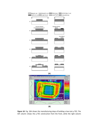
![shows a side view. A combination of eight materials was used, each shown at the top
of the figure along with its graphical representation. This bridgetype had a much
smaller area to length ratio, which increased the thermal resistance, making it the
better manufacturing choice for μTECs. Fig. 10B shows a heatmap (topdown view) of
the temperature distribution across the bridgetype polysiliconbased
microthermoelectric cooler (μTEC) Huang, et al. built. Dark blue is the coldest of
regions and the warmer regions are increasingly more red. Whereas the columntype
telluridebased μTEC achieved a 1.2K temperature difference across the heated
surface, this bridgetype achieved a 5.6K temperature difference. The μTEC works by
employing the Peltier effect, where heat is transferred between two different
materials via a DC voltage. [10]
Conclusion
Heat dissipation in laptops and other such electronics is becoming an increasingly important
issue with the advent of more and more powerful processors combined with the ubiquity of
computing. In this paper, we have identified and briefly evaluated some of the MEMS technologies
designed to cool electrical components for laptops. Impingement, heat exchangers and sinks, and
electric field based liquid cooling are presented, and the paper ends with some other promising
technologies. Impingement and heat sinks offer the highest heat transfer rates while the
controllability of liquids using electric fields has its own benefits. Although impingement and heat
sinks have the advantage of higher heat transfer rates, 420 W/cm2
with impingement bifurcation and
up to 500 W/cm2
with a closed loop microheat exchanger system, they both suffer from problems
with high pressure drops. Electrohydrodynamic cooling avoids this problem, but tend to have much
lower heat transfer rates. Some other promising technologies use high voltages to ionize air to induce
flow, while others avoid convection as the primary mode of heat dissipation using the Peltier effect
(μTECs). Further research involving the specific constraints of laptops (such as space and fluid flux)
when incorporating these systems should be done before adoption.](https://image.slidesharecdn.com/fccb216b-54ee-4c74-ad12-c36190c9d358-160704204802/85/Methods-of-Heat-Dissipation-in-Laptops-Using-MEMS-10-320.jpg)


