Download to read offline
![International Journal of Advances in Engineering & Technology, Dec., 2017.
©IJAET ISSN: 22311963
613 Vol. 10, Issue 6, pp. 613-618
ACTIVE SAFETY CONTROL TECHNIQUE TO PREVENT
VEHICLE CRASHING
Rupesh S. Bobade1
and Shrikant K. Yadav2
1,2
Department of Mechanical Engineering,
MIT College of Engineering, Pune, MH, India
ABSTRACT
Alertness during driving is a key aspect. Even a small distraction for the driver may lead to genuine mishaps.
The possible reasons can be obstacle, inadequate vehicle control system or human reflexes (e.g. shock) during
sudden distraction. Therefore "Active" and "Passive" systems for vehicle control play a significant role in
automotive safety. In this paper, we have discussed an active control technique to prevent the vehicle from
crashing. Three different cases of vehicle speed are considered. The presented technique is designed to evaluate
the possibility of collision for both front and rear side. The control action will be taken for safe and smooth
driving under different situations like parking, urban driving and highway driving.
KEYWORDS: Active, Passive, Control system, Vehicle speed
I. INTRODUCTION
Road accident is one of major issues related to public health. According to WHO, over 1.25 million
road traffic deaths occurred each year [1]. The Ministry of road transport and highways Govt. of India
published close to 5 lakh road accidents in the year 2015 [2]. There can be multiple reasons for road
accidents, however one of vital concern is crashing or collision of automobiles against an obstacle. In
order to protect loss of life, vehicle manufactures often implement various safety systems. These
safety systems mainly divided into two categories: Active Safety system and Passive Safety system.
The active safety system or primary safety or driver assistance system mainly includes features that
work to prevent the risk of a collision or an accident. These features are always active to prevent an
accident. Passive Safety systems or secondary safety or crashworthy system, on the other hand, are
passive until called into action. The passive features become active during the accident and aim to
help minimize the damage from the collision [3].
Active system has a main purpose to assist in the prevention of crashes. It is active "prior" to an
accident. Passive system has a main purpose to protect occupants during a crash. It is active during an
accident. Different examples of Active and Passive safety control systems which are currently used on
a vehicle are shown in Fig. 1.](https://image.slidesharecdn.com/5i42-ijaet1006211-v10-i6-pp613-618-180205120650/75/ACTIVE-SAFETY-CONTROL-TECHNIQUE-TO-PREVENT-VEHICLE-CRASHING-1-2048.jpg)
![International Journal of Advances in Engineering & Technology, Dec., 2017.
©IJAET ISSN: 22311963
614 Vol. 10, Issue 6, pp. 613-618
Fig.1: Examples of Active & Passive safety control systems
In this paper, we have proposed an active control technique to prevent the vehicle from crashing.
Three different cases of vehicle speed are considered .i.e.
1. Vehicle speed <= 10 KMPH (e.g. Parking)
2. Vehicle speed = 40 KMPH to 60 KMPH (e.g. Urban driving)
3. Vehicle speed >= 60 KMPH (e.g. Highway driving)
The proposed control technique is designed to evaluate the possibility of collision for both front and
rear side. As seen before, there are multiple ways to implement an active system. In this paper, we
have presented an economical and effective way of control technique with the use of basic systems of
the vehicle. The proposed control action will be taken for safe and smooth driving [4].
This paper is organized as follows: Next section presents the proposed active safety control technique.
The section details the idea with flowcharts and control system. The last section concludes the
findings.
II. ACTIVE SAFETY CONTROL TECHNIQUE
The Adaptive Cruise Control (ACC) (which keeps the automobile at pre-defined safer distance from
the preceding vehicle) is already exists where the vehicle control system is combined with cruise
control. The vehicle speed control technique in particular zones is already proposed [5,9]. In some
systems, vehicle gives a buzzer signal to the intimate driver to slow down vehicle otherwise vehicle
speed controlled automatically [6].In this paper, the active control technique is proposed to prevent
the vehicle from crashing is presented. When the vehicle is moving with speed more than average
speed (40 kmph and above), the reaction by the driver for controlling speed of the vehicle when
obstacle come up is very important. Sometimes, the driver may not be able to control the vehicle
because of the short time and sudden shock, which results in crash of a vehicle to obstacle.[10]
The proposed active safety system is a helping hand for the driver to control vehicle speed so that
vehicle crashing and respective mishaps gets prevented. In this system, the vehicle is controlled by
reducing engine speed as well as braking action. For actuation of the system, inputs from wheel speed
sensors and ultrasonic wave sensor are important parameters. From these inputs controller will
evaluate the possibility of collision and takes corrective action.](https://image.slidesharecdn.com/5i42-ijaet1006211-v10-i6-pp613-618-180205120650/75/ACTIVE-SAFETY-CONTROL-TECHNIQUE-TO-PREVENT-VEHICLE-CRASHING-2-2048.jpg)
![International Journal of Advances in Engineering & Technology, Dec., 2017.
©IJAET ISSN: 22311963
615 Vol. 10, Issue 6, pp. 613-618
An engine control unit (ECU) controls different actuators on an IC engine to ensure optimal engine
performance. Fig. 2 shows the layout of the engine speed control system. The basic elements of an
engine control system of the kind that led to development of regulators are, 1. A valve which regulates
supply rate of compressed air, 2.MAF sensor, 3.An output shaft with flywheel and engine load [7].
Fig.2: Engine Speed Control System
As shown in Fig. 2, the compressed air can be controlled using the driver motor and throttle valve. If
x(t) is defined as the valve position and motor input as u(t). Then, the rate of change of valve position
ẋ(t)is proportional to motor input signal u(t).
ẋ(t)α u(t) (i)
Similar if p(t) is defined as valve output pressure and TE(t) as engine torque then valve output pressure
p(t) is proportional to valve position x(t). The engine torque is proportional to air pressure. And the
angularωE(t) velocity of engine can be calculated from engine torque,
p(t)α x(t) (ii)
TE(t)α p(t) (iii)
ωE(t)αTE(t) (iv)
The momentum of the vehicle cannot be addressed only by engine control. So, the automatic braking
system is also needed. The brake gets applied through ECU action on ABS and vehicle speed gets
controlled as per the requirement [8].
Fig.3: Vehicle Speed Control System](https://image.slidesharecdn.com/5i42-ijaet1006211-v10-i6-pp613-618-180205120650/75/ACTIVE-SAFETY-CONTROL-TECHNIQUE-TO-PREVENT-VEHICLE-CRASHING-3-2048.jpg)
![International Journal of Advances in Engineering & Technology, Dec., 2017.
©IJAET ISSN: 22311963
618 Vol. 10, Issue 6, pp. 613-618
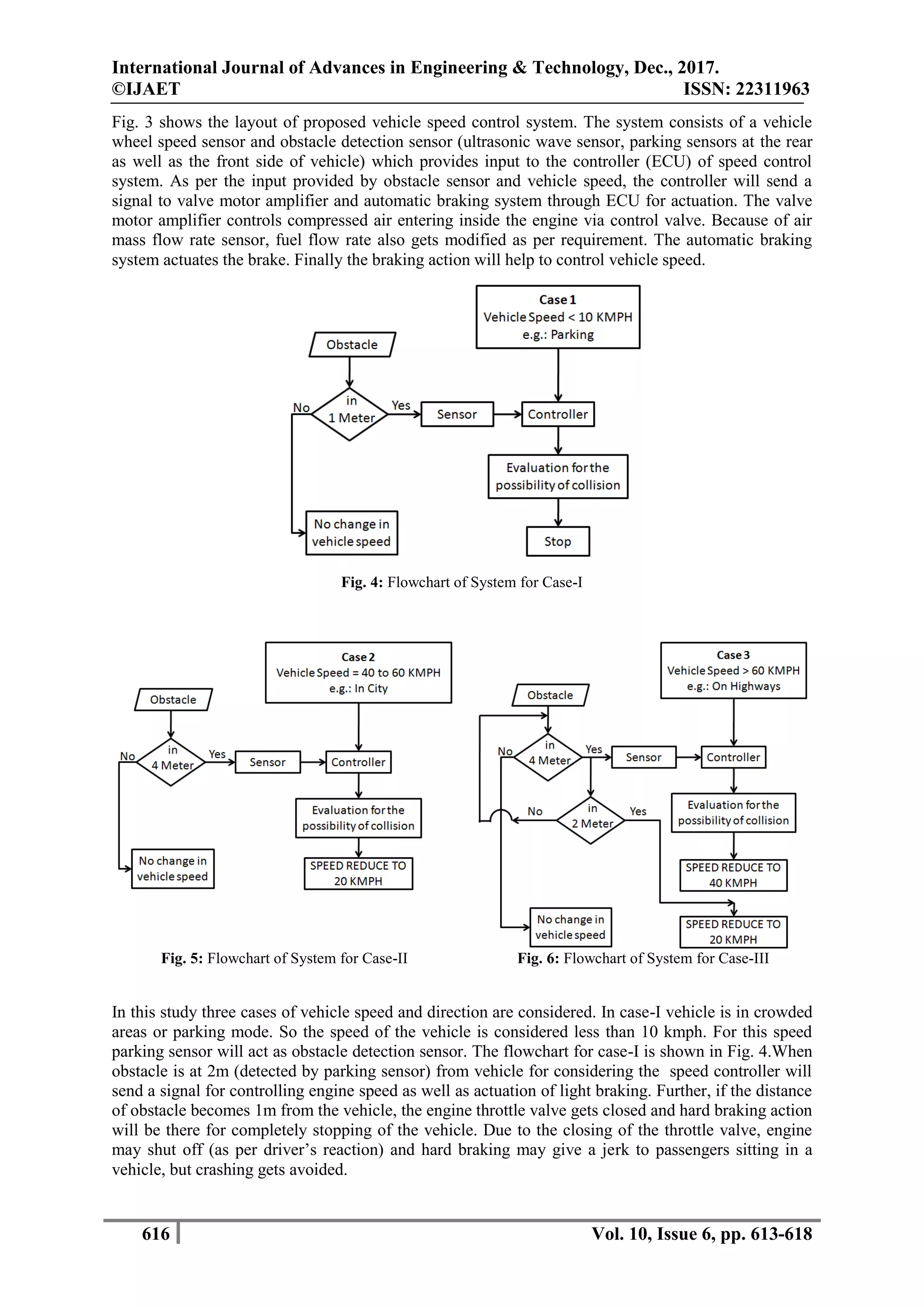
In second and third case the final speed of the vehicle is 20 kmph. With this speed if vehicle collides
with an obstacle, then the possibility of damage to the vehicle or injury to passengers will be less. It
shows, even if the driver feels the shock, the active control system will assist to slow down vehicle
speed. Table 1 represents actions taken by controller for providing sensor signal for different case
studies.
The last two columns of the table represent the new vehicle speed with remarks on controller action.
These actions of the controller are represented in fig. 7.
III. CONCLUSION AND FUTURE SCOPE
An active safety control system is presented to prevent the vehicle from crashing. The proposed
technique is designed to manage vehicle speed using engine control and braking action against an
obstacle. The control system is set to use the sensor output for evaluating the possibility of collision
for both front and rear side. The control action will be taken for safe and smooth driving under three
different vehicle speed situations like parking, urban driving and highway driving. In addition, the
proposed control technique does not need an expensive sensor which otherwise is a common practice
for active safety control of the vehicle. We propose, basic system of vehicle with proposed control
logic to have an effective safety of the vehicle against crashes. In future scope, the proposed control
system will be implemented and prior test will be carried out.
REFERENCES
[1] World Health Organization (WHO), "Global Status Report on Road Safety 2015", Link:
http://www.who.int/violence_injury_prevention/road_safety_status/2015/en/
[2] The Ministry of road transport and highways Govt. of India, "Road accidents in India 2015", Link:
http://pib.nic.in/newsite/PrintRelease.aspx?relid=146093
[3] Rahul Waghe, Dr. S Y.Gajjal, 2014, "Study of Active and Passive Safety Systems and Rearview Mirror
Impact Test", SSRG International Journal of Mechanical Engineering (SSRG-IJME) – volume1 issue 3, ISSN:
2348 – 8360, pp. 10-15
[4] MuntaserMomani, 2012, “Collision Avoiding System (CAS)", Contemporary Engineering Sciences, Vol. 5,
no. 7, 341 - 354
[5] GummarekulaSattibabu,, B.V.V.Satyanarayan, VvSatyanarayana Kona, 2014, “Automatic Vehicle Speed
Control With Wireless In-Vehicle Road Sign Delivery System Using Arm 7 ”, International Journal of
Technology Enhancements And Emerging Engineering Research, Vol2, Issue 8, ISSN 2347-4289, pp 32-34.
[6] Amarnarayan, ChallaSaikumar et all, 2016, “Automatic Over speed Controlling of Vehicle”, International
Journal of Combined Research and Development, ISSN 2321-225, Vol 5, Issue 5, pp 706-709.
[7] ZhenggangXu, XiaopengXie, 2009, "A method for reducing exhaust pressure of vehicle compressed air
powered engine", IEEE International Conference onMechatronics andAutomation, ICMA 2009. Changchun,
China.
[8] TakeshiWakabayashia, TakushiMatsutoa, KazhuikoTanib, AtsuoOhtaa, 1998, "Development of motor
actuated antilock brake system for light weight motorcycle", New Technologies & NewCars, JSAE Review,
Volume 19, Issue 4, 1 October 1998, Pages 373-377.
[9] A.Vengadesh ,K.Sekar, 2015, “Automatic Speed Control of Vehicle in Restricted Areas Using RFand
GSM”, International Research Journal of Engineering and Technology, Volume 2, Issue 9, pp 875-877.
[10] Mr.M.V.N.R.Pavankumar ,Mr. Deepak S. Kesare, Mr. Mangesh B. Pawar, Mr. Pramod R. Khande,
“Highway Speed Control and Automatic Breaking System”International Journal of Research in Advent
Technology, Vol.3, No.5, May 2015, pp 59-62.](https://image.slidesharecdn.com/5i42-ijaet1006211-v10-i6-pp613-618-180205120650/75/ACTIVE-SAFETY-CONTROL-TECHNIQUE-TO-PREVENT-VEHICLE-CRASHING-6-2048.jpg)

The paper discusses an active safety control technique aimed at preventing vehicle crashes by evaluating collision possibilities under varying speed conditions (parking, urban, and highway driving). It emphasizes the importance of integrating engine control and automatic braking systems to assist drivers in managing vehicle speed and avoiding obstacles. The proposed system utilizes basic vehicle components to enhance safety without requiring expensive sensors.