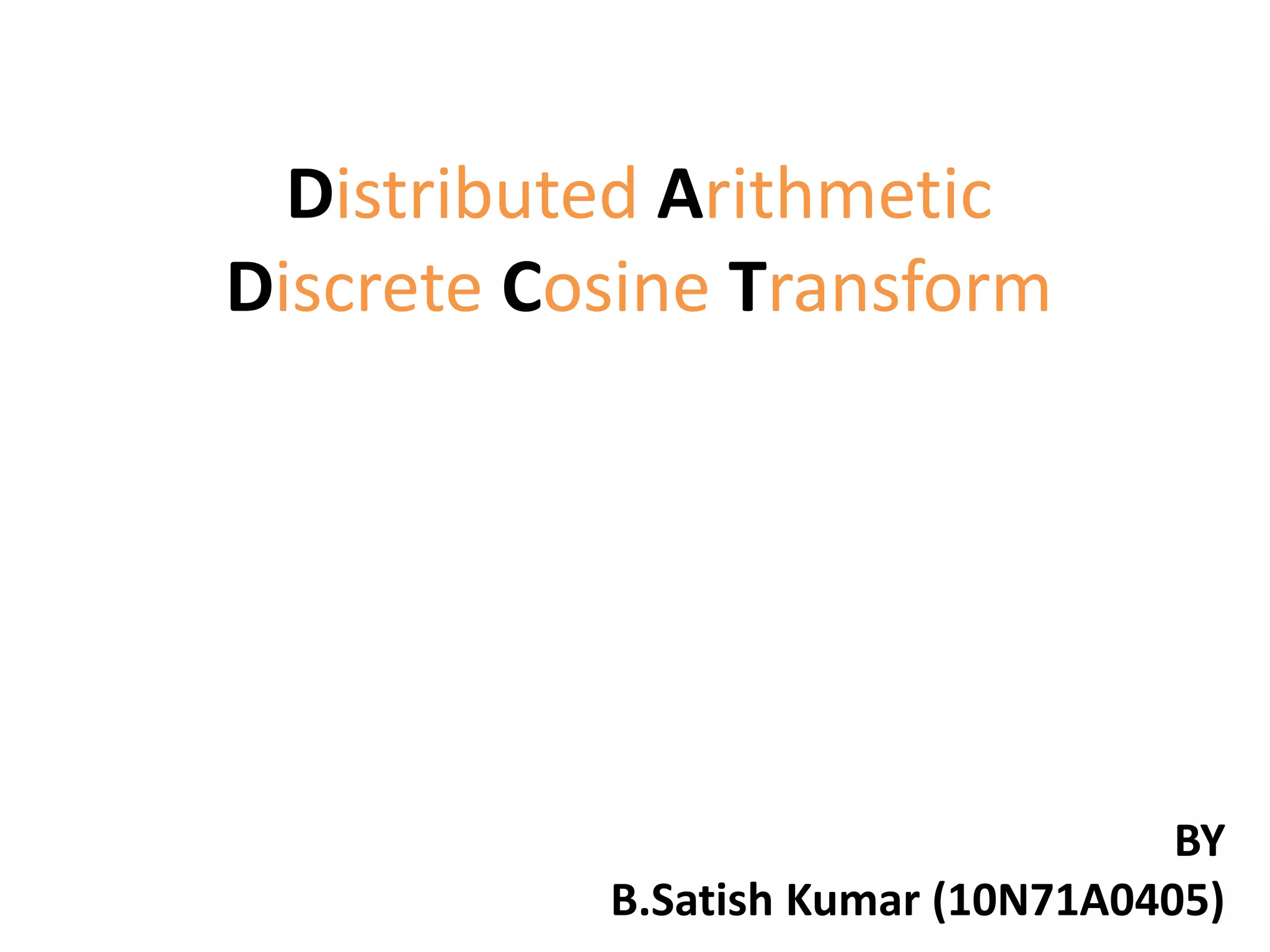
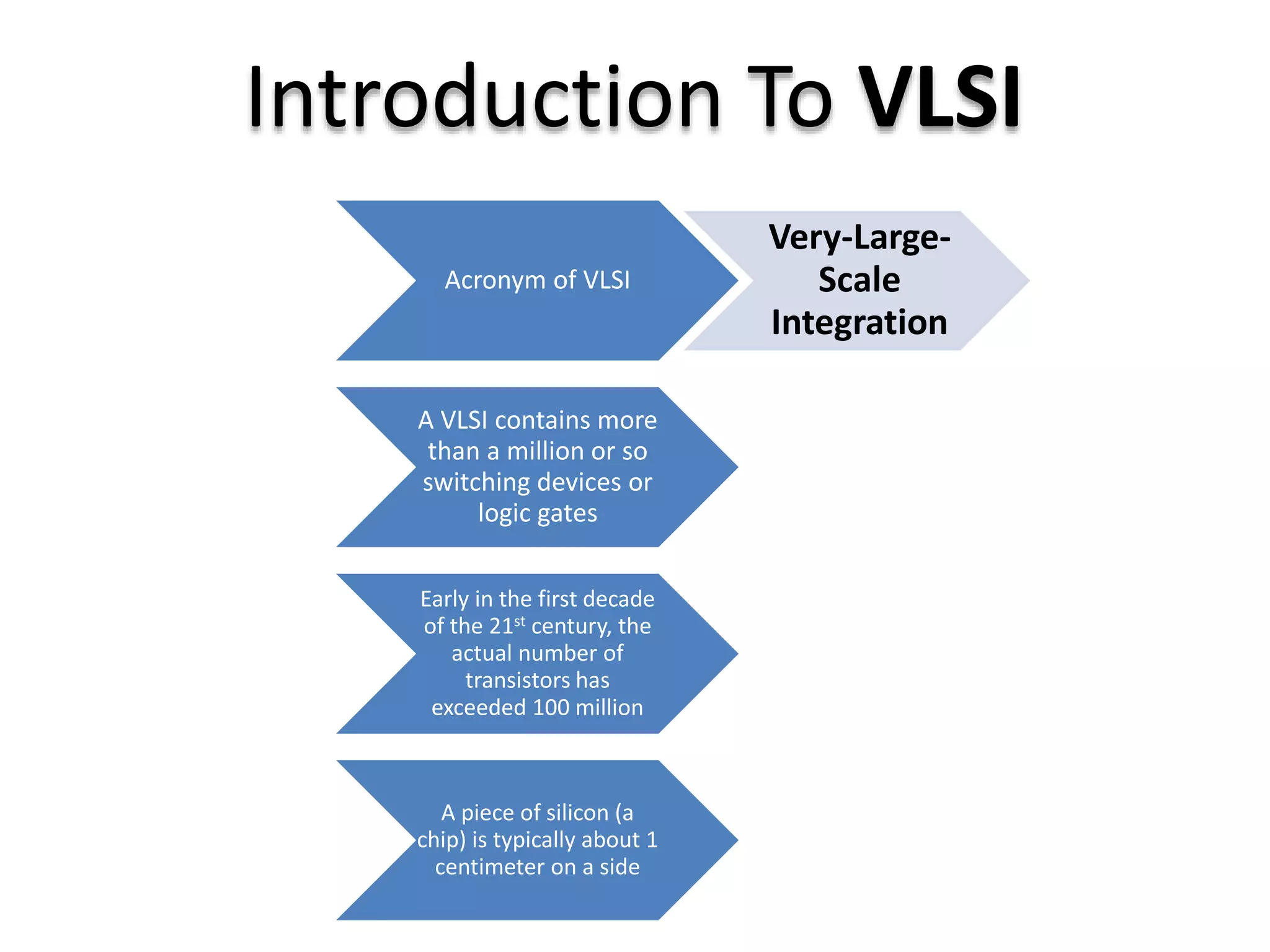
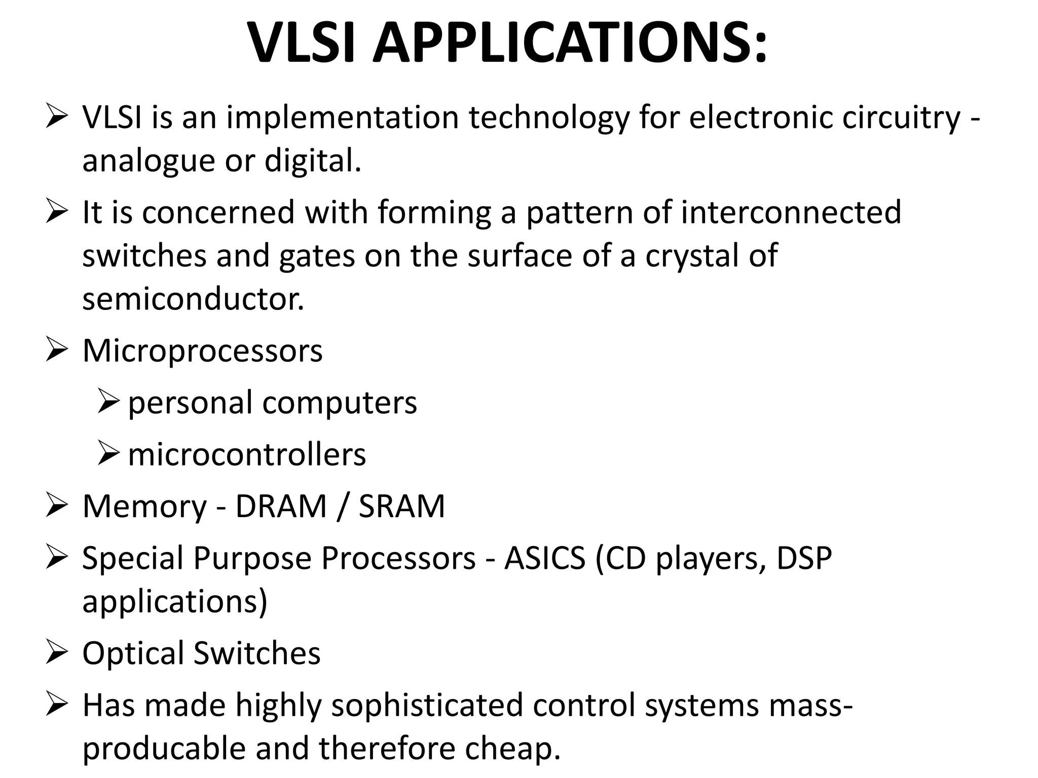
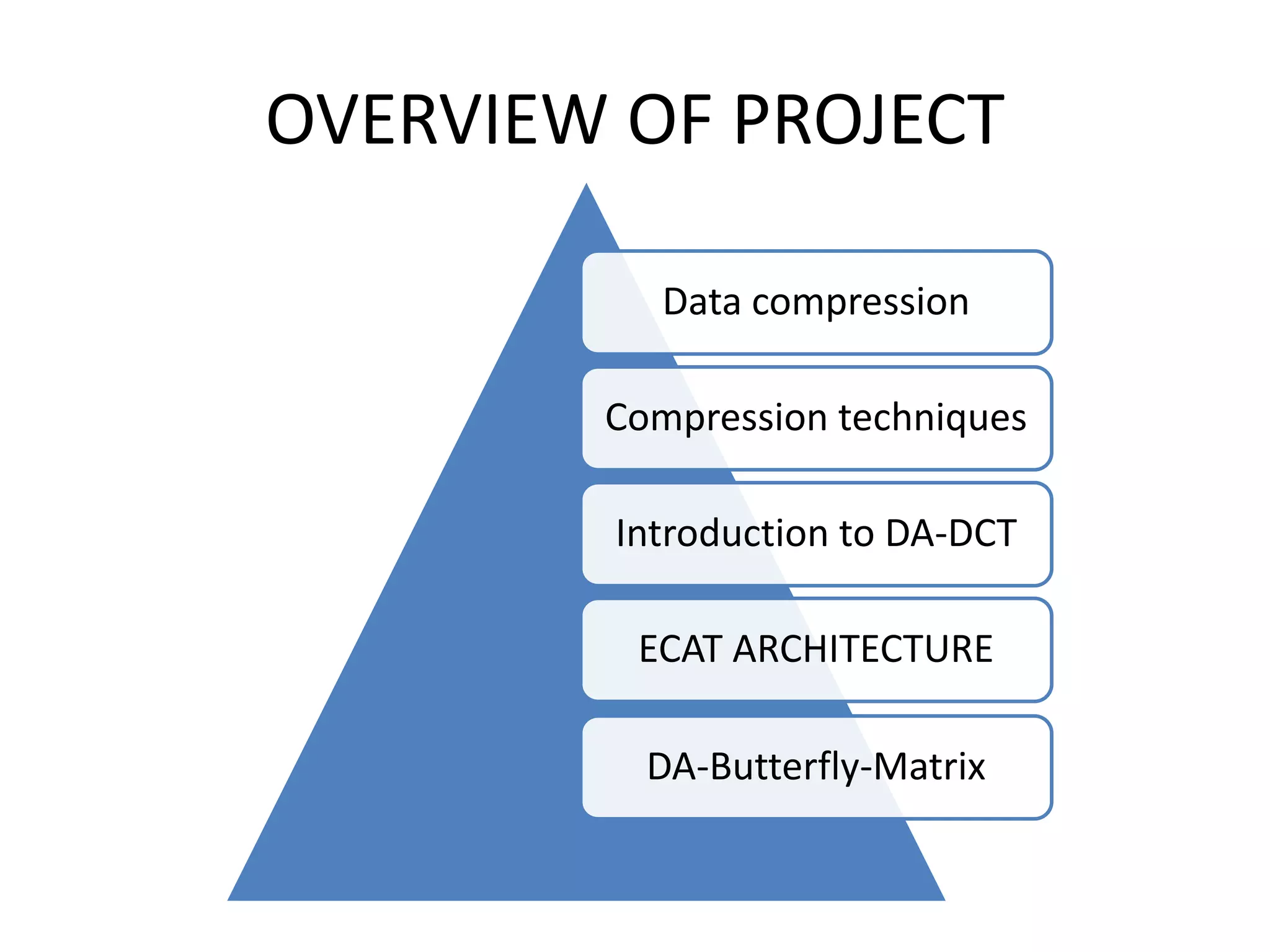
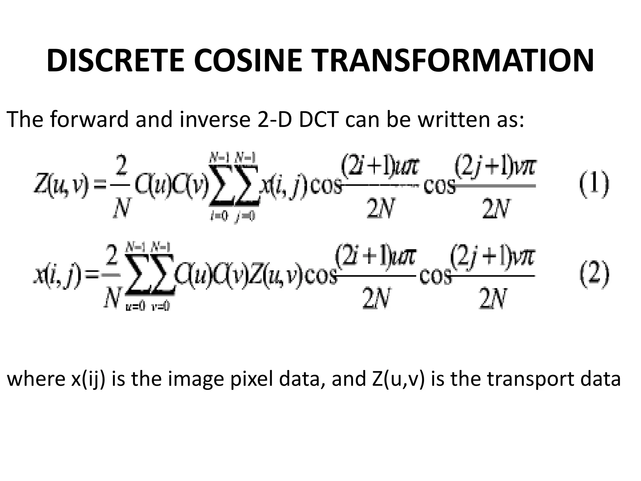
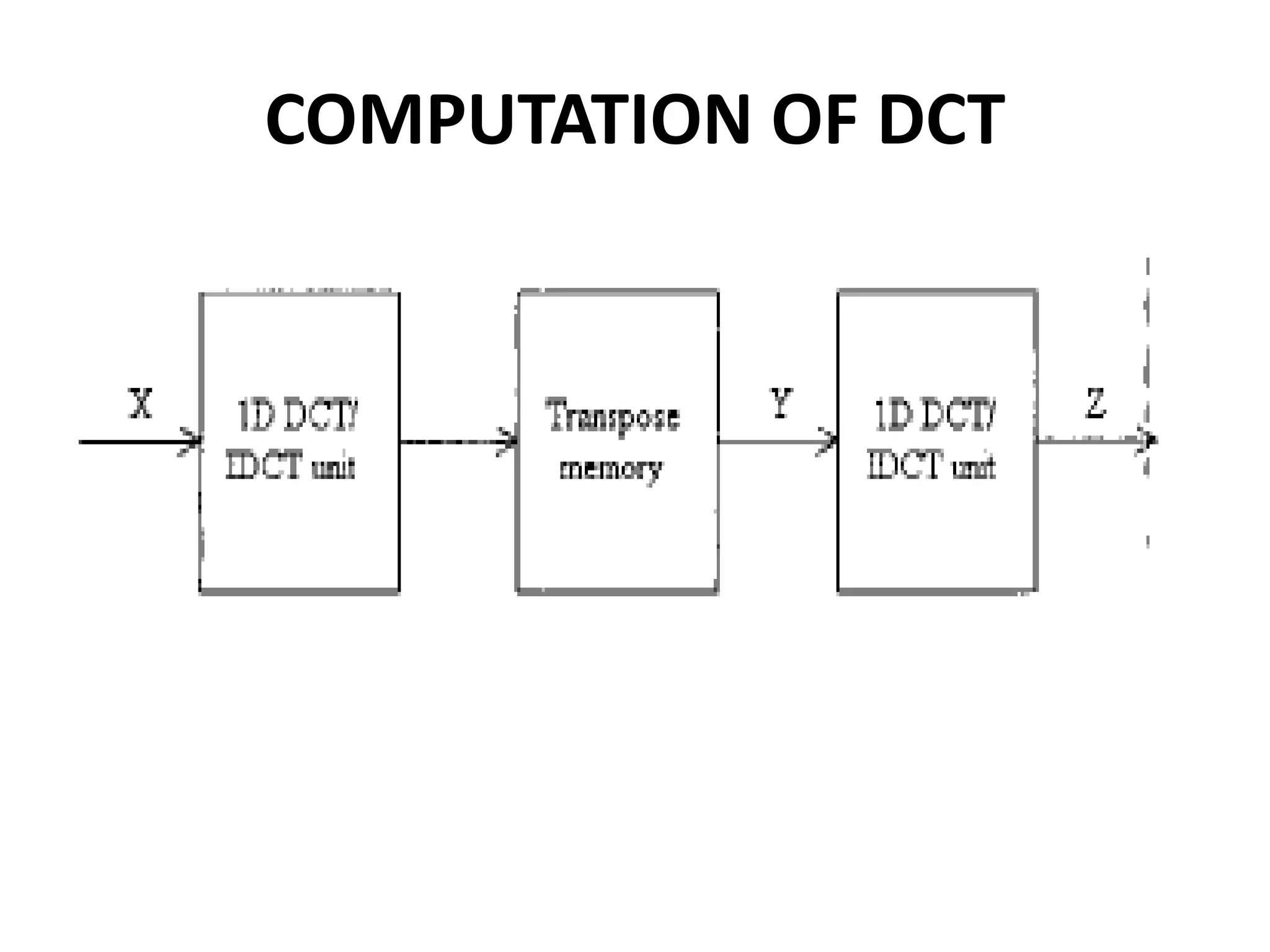
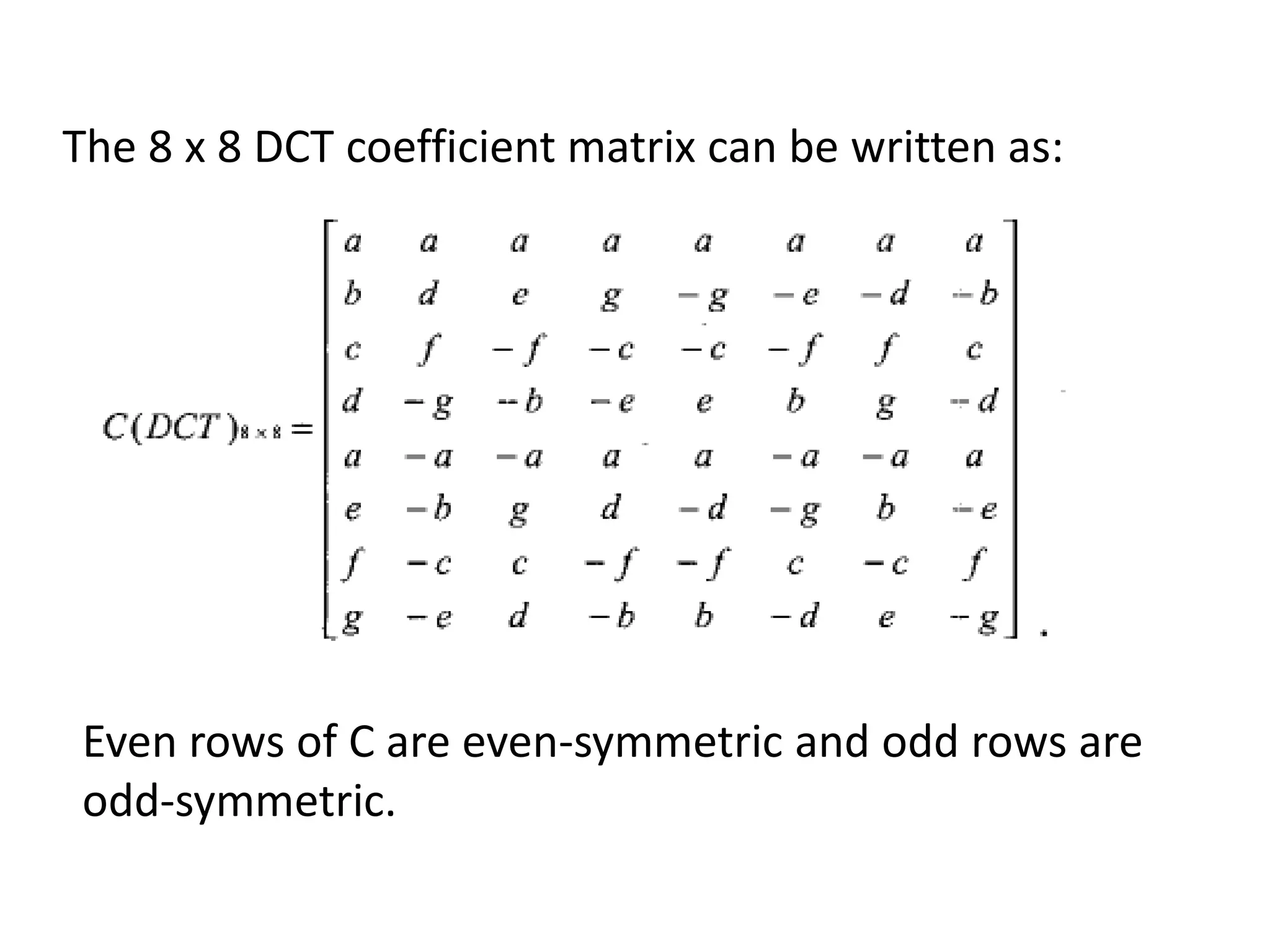
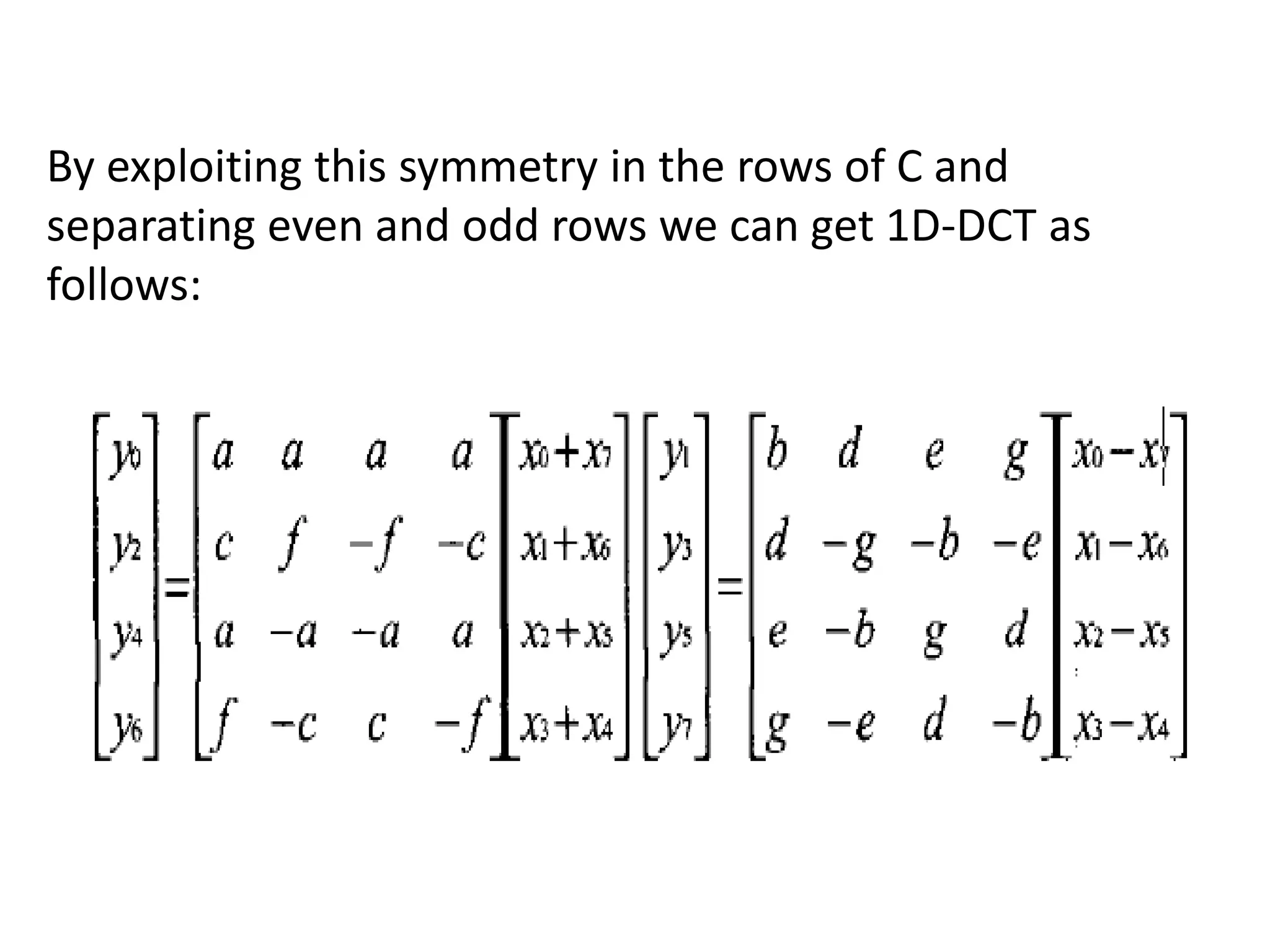
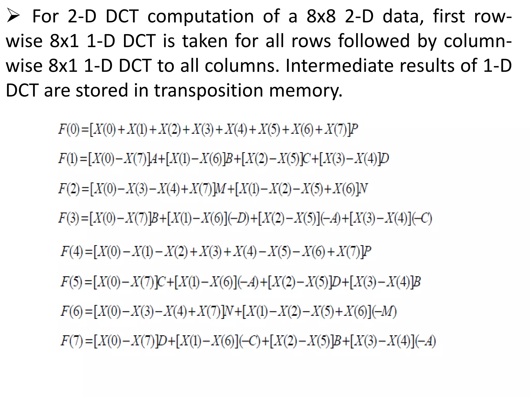
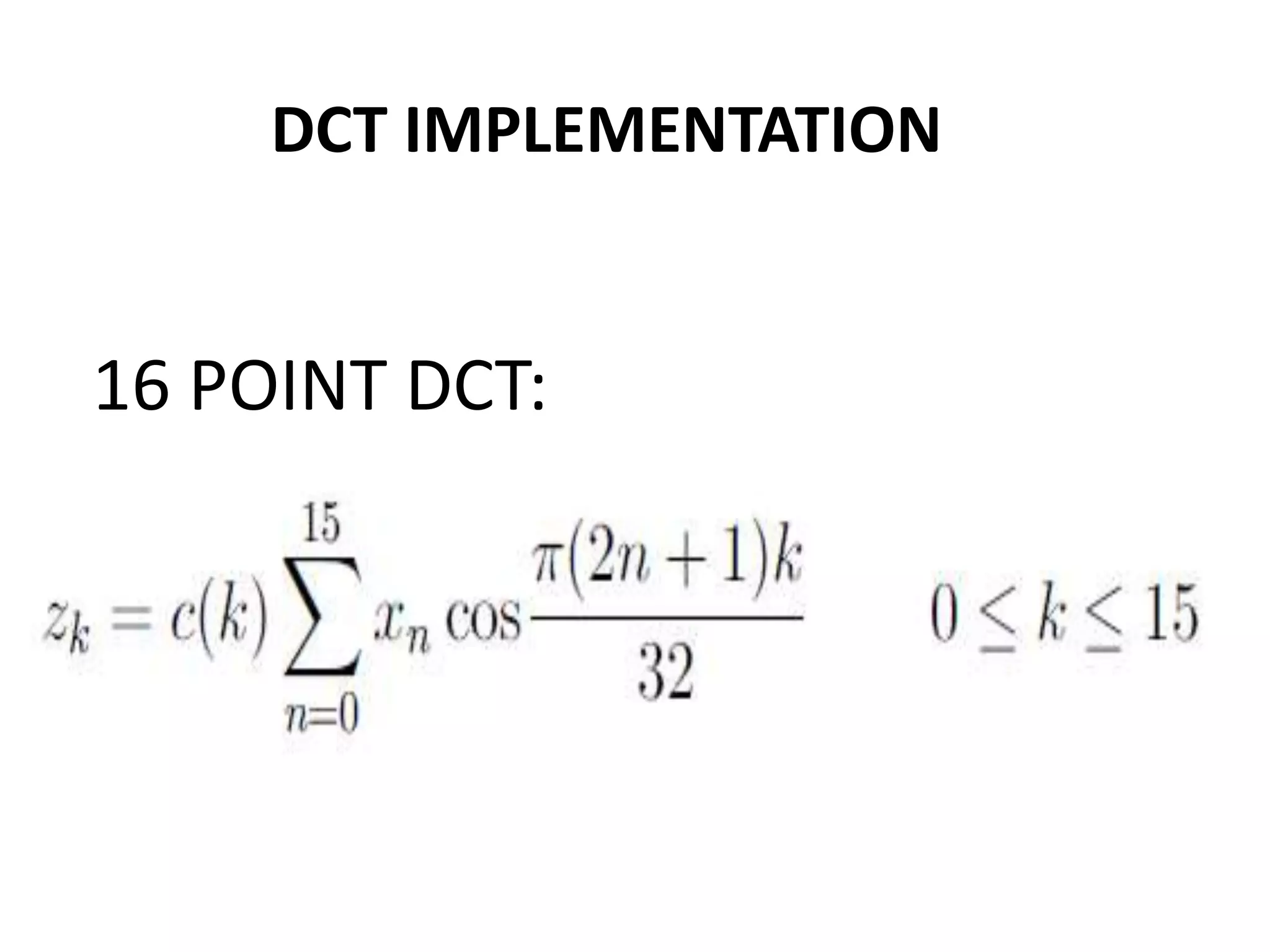
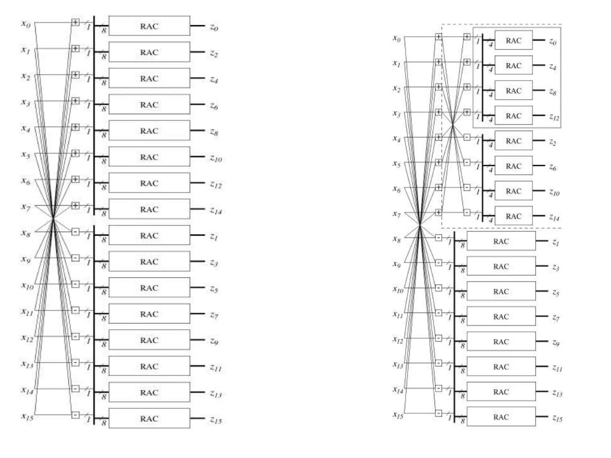
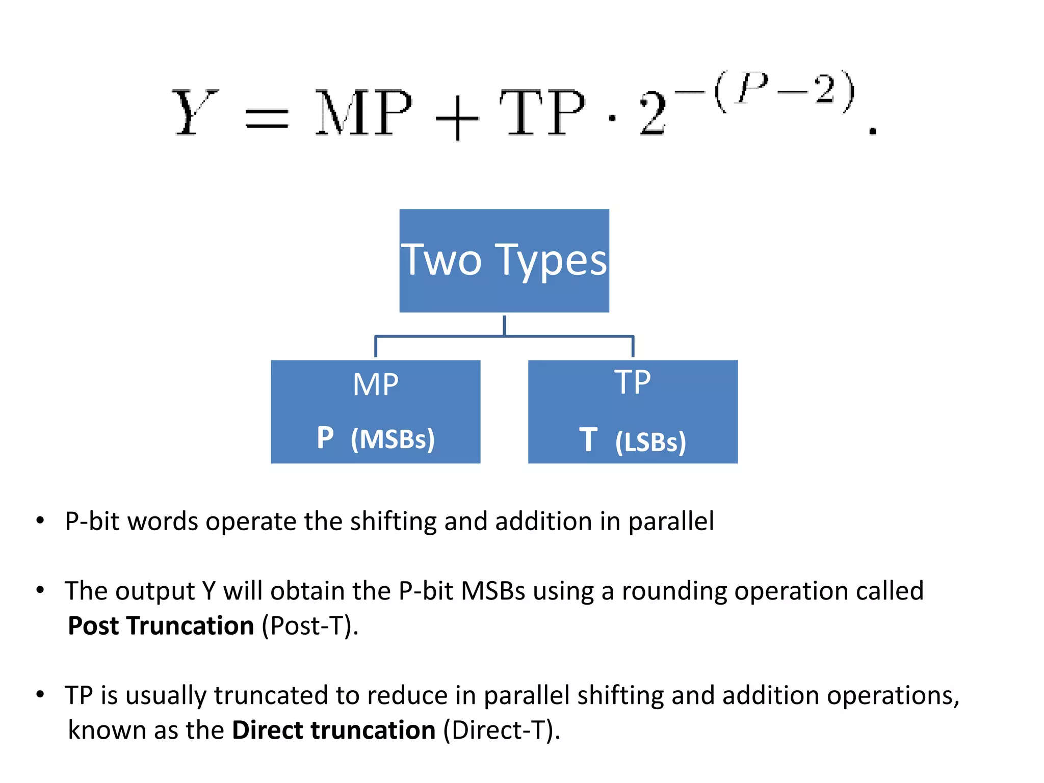
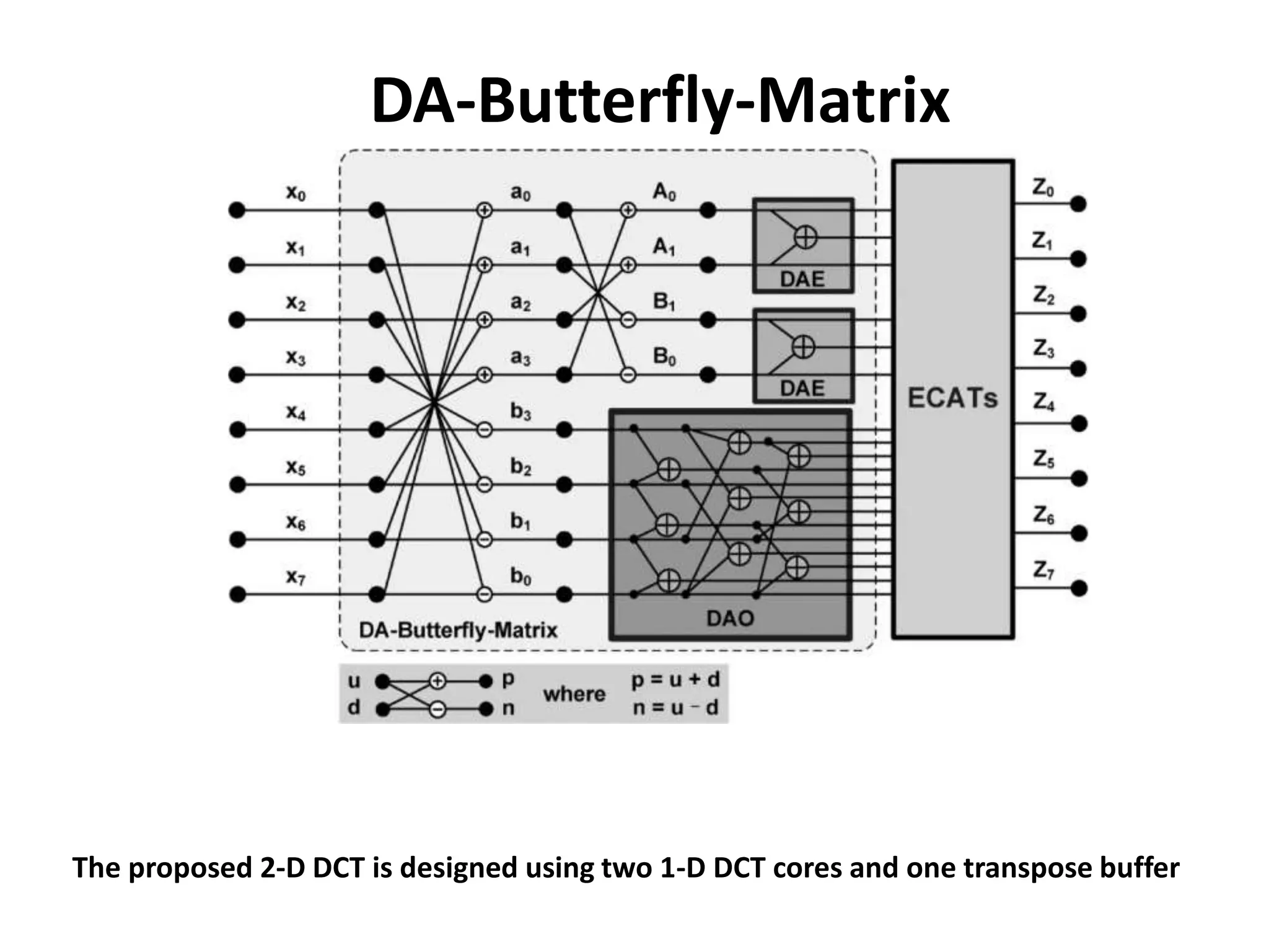
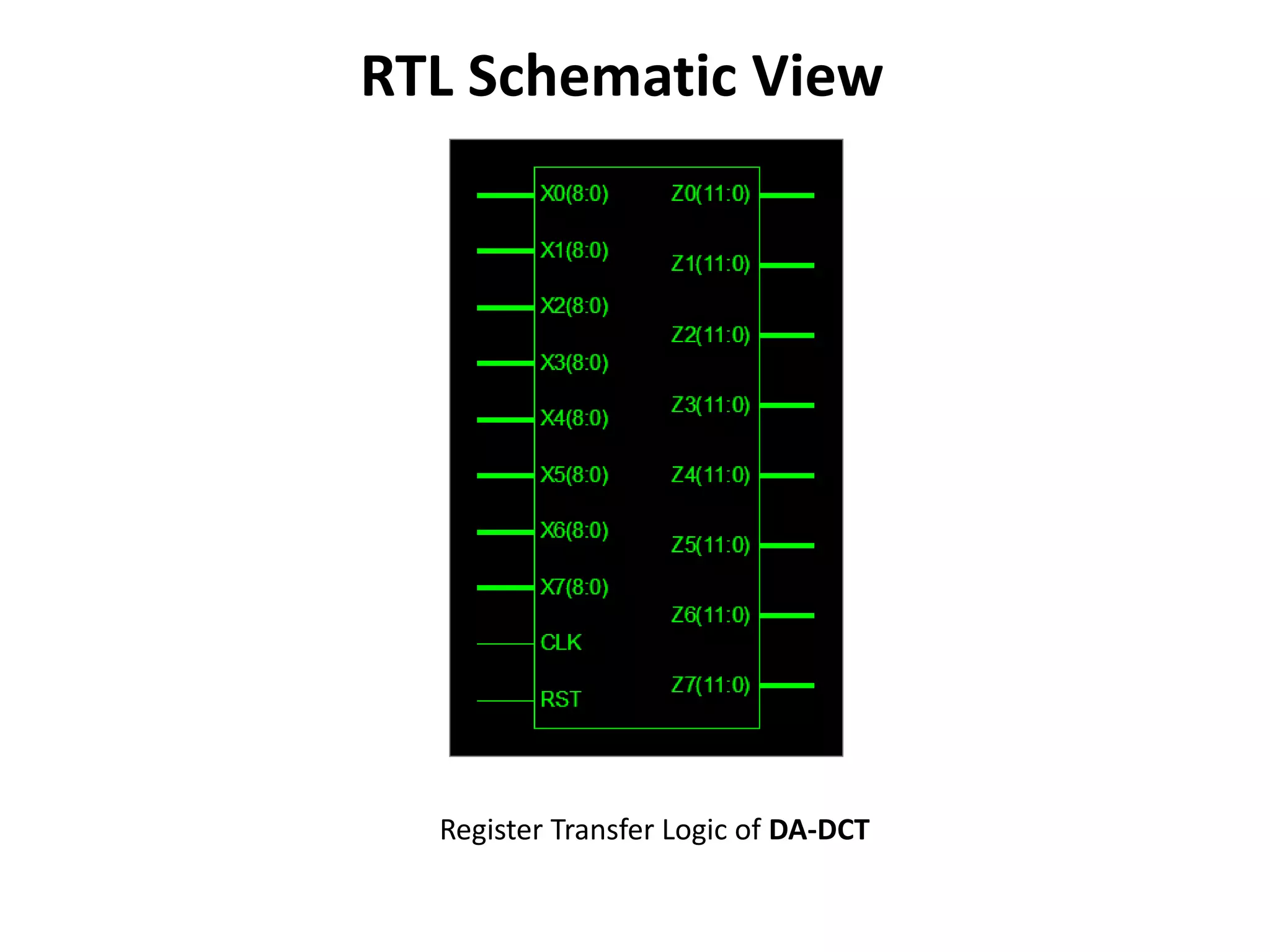
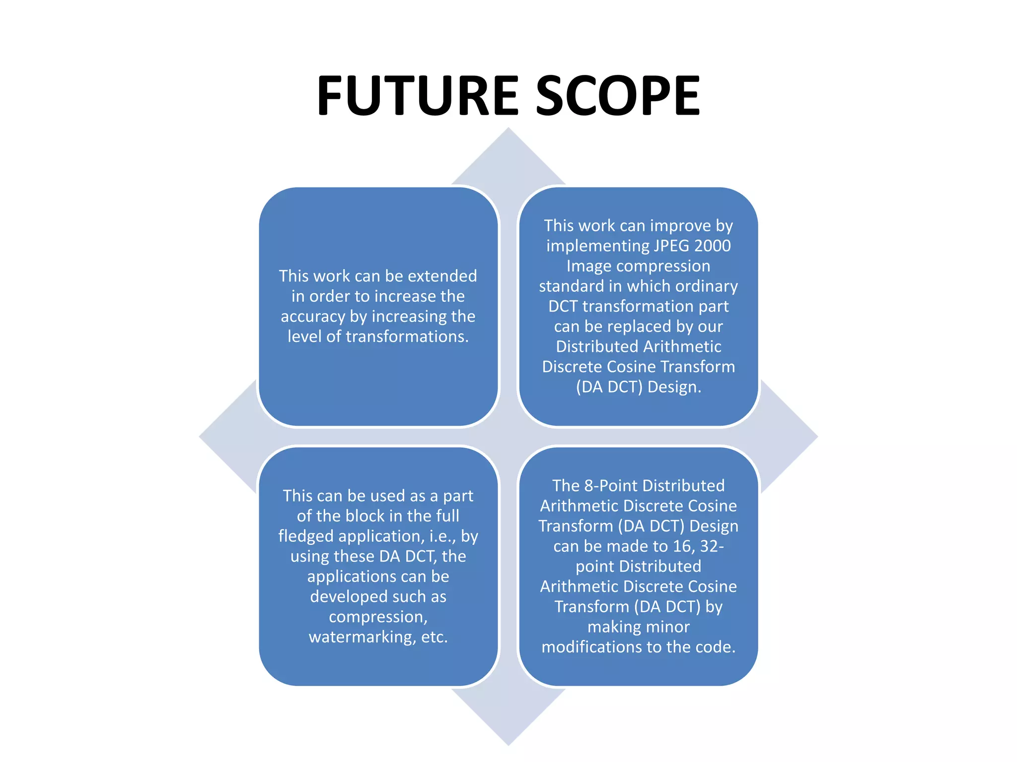
Distributed Arithmetic
Discrete Cosine Transform
BY
B.Satish Kumar (10N71A0405)
Introduction To VLSI
Acronym of VLSI
Very-Large-
Scale
Integration
A VLSI contains more
than a million or so
switching devices or
logic gates
Early in the first decade
of the 21st century, the
actual number of
transistors has
exceeded 100 million
A piece of silicon (a
chip) is typically about 1
centimeter on a side
HDL (Hardware Descriptive Language)
HDL is a specialized computer language used to
describe the structure, design and operation
of electronic circuits, and most
commonly, digital logic circuits.
The two most widely-used and well-supported
HDL varieties used in industry are ”Verilog(verify
logic)” and ”VHDL( (Very High Speed Integrated
Circuit) Hardware Description Language)”.
VLSI APPLICATIONS:
 VLSI is an implementation technology for electronic circuitry -
analogue or digital.
 It is concerned with forming a pattern of interconnected
switches and gates on the surface of a crystal of
semiconductor.
 Microprocessors
personal computers
microcontrollers
 Memory - DRAM / SRAM
 Special Purpose Processors - ASICS (CD players, DSP
applications)
 Optical Switches
 Has made highly sophisticated control systems mass-
producable and therefore cheap.
INTRODUCTION TO XILINX ISE
The ISE® Design Suite is the Xilinx® design
environment, which allows you to take your
design from design entry to Xilinx device
programming.
WHY XILINX ISE?
The ISE Design Suite: Logic Edition allows you to
go from design entry, through implementation and
verification, to device programming from within
the unified environment of the ISE Project
Navigator or from the command line.
DESIGN MODULES IN XILINX:
VERILOG
MODULE
VHDL
MODULE
VERILOG MODULE:
Verilog, standardized as IEEE
1364, is a hardware description
language (HDL) used to model
electronic systems.
It is most commonly used in the
design and verification of digital
circuits at the register-transfer
level of abstraction.
It is also used in the verification
of analog circuits and mixed-
signal circuits.
OVERVIEW OF PROJECT
Data compression
Compression techniques
Introduction to DA-DCT
ECAT ARCHITECTURE
DA-Butterfly-Matrix
DATA COMPRESSION
 Despite the many advantages of digital
representation of signals compared to the analog
counterpart, they need a very large number of bits for
storage and transmission.
 For Example, a high-quality audio signal requires
approximately 1.5 megabits per second for digital
representation and storage.
A television-quality low-resolution color video of 30
frames per second with each frame containing 640 x
480 pixels (24 bits per color pixel) needs more than
210 megabits per second of storage.
As a result, a digitized one-hour color movie would
require approximately 95 gigabytes of storage. The
storage requirement for upcoming high-definition
Television (hdtv) of resolution 1280 x 720 at 60
frames per second is far greater.
CODEC
The compression and decompression systems together called a CODEC.
TYPES OF COMPRESSION:
LOSSLESS
COMPRESSION
LOSSY
COMPRESSION
Depending on the output requirements either of the compression
techniques are used.
COMPRESSION TECHNIQUES
INTRODUCTION TO DA-DCT
DISTRIBUTED
ARITHMATIC-
DISCRETE
COSINE
TRANSFORM
DCT(DISCRETE COSINE TRANSFORM):
Discrete cosine transform (DCT) is a
widely used tool in image and video
compression applications.
Recently, the high-throughput DCT
designs have been adopted to fit the
requirements of real-time application.
STEPS INVOLVED IN COMPRESSION OF
THE IMAGE
Dividing the image
into pixels and
level shifting
them.
DCT is performed
on the pixels
resulting in DCT
blocks.
Quantization is
done on these
blocks.
Quantized
matrices are
arranged in zigzag
order to
differentiate low
frequency
components and
high frequency
components.
The encoder block
encodes the
quantized data
Zero run and
huffman coding
techniques are
used to encode
the data in
encoder block.
REDUNDANCY CODING
To remove the unnecessary data while coding is
called as Redundancy Coding.
Types of Redundancies
Coding
redundancy
Inter pixel
redundancy
Psycho-visual
redundancy
DISCRETE COSINE TRANSFORMATION
The forward and inverse 2-D DCT can be written as:
where x(ij) is the image pixel data, and Z(u,v) is the transport data
COMPUTATION OF DCT
The 8 x 8 DCT coefficient matrix can be written as:
Even rows of C are even-symmetric and odd rows are
odd-symmetric.
By exploiting this symmetry in the rows of C and
separating even and odd rows we can get 1D-DCT as
follows:
 For 2-D DCT computation of a 8x8 2-D data, first row-
wise 8x1 1-D DCT is taken for all rows followed by column-
wise 8x1 1-D DCT to all columns. Intermediate results of 1-D
DCT are stored in transposition memory.
DCT IMPLEMENTATION
16 POINT DCT:
ECAT ARCHITECTURE
Error-Compensated Adder Tree
ECAT Architecture For Distributed Arithmetic Based DCT
• DA-based architecture and the proposed ECAT to achieve a high-speed,
small area and low-error design.
• It is proposed to compensate for the truncation error in high-speed applications.
• Reduces the shifting and addition computation time .
Two Types
MP
P (MSBs)
TP
T (LSBs)
• P-bit words operate the shifting and addition in parallel
• The output Y will obtain the P-bit MSBs using a rounding operation called
Post Truncation (Post-T).
• TP is usually truncated to reduce in parallel shifting and addition operations,
known as the Direct truncation (Direct-T).
Proposed Error-Compensated Scheme
Where is the compensated bias from the TP to the MP
Proposed ECAT Architecture
• Full - Adder
• Cell with three inputs (a, b, c)
• Two outputs, a sum (s) and a carry-out (co)
• Half - Adder
• Two inputs (a &b)
• Two outputs, a sum (s) and a carry-out (co)
Proposed ECAT architecture of shifting and addition operators
PROPOSED 8*8 1-D DCT CORE DESIGN
xm Denotes the input data.
Zn Denotes the transform output.
Above equation can be divided into even and odd parts: Ze and Zo
DA-based computation, the coefficient matrix Cee and Ceo
DA-Butterfly-Matrix
The proposed 2-D DCT is designed using two 1-D DCT cores and one transpose buffer
GENERAL IMPLEMENTATION FLOW
RTL Schematic View
Register Transfer Logic of DA-DCT
Simulation results of Distributed Arithmetic DCT
Device Utilization Summary:
Timing Summary:
Speed Grade: -4
• Minimum period: No path found
• Minimum input arrival time before clock: 23.566ns
• Maximum output required time after clock: 4.283ns
• Maximum combinational path delay: No path found
ADVANTAGES
The main advantage of compression is that it reduces
the data storage requirements.
It also offers an attractive approach to reduce the
communication cost in transmitting high volumes of
data
This significantly aids in reducing the cost of
communication due to the data rate reduction.
Hence the audience can experience rich-quality
signals for audio-visual data representation.
we can receive toll-quality audio at the other side of
the globe at a much better price compared to a
decade ago.
A single 6 MHz broadcast television channel can
carry HDTV signals.
Because of the reduced data rate offered by the
compression techniques, computer network and
Internet usage is becoming more and more image and
graphic friendly, rather than being just data- and text-
centric phenomena.
SECONDARY ADVANTAGES
Data compression has great implications in
database access.
Data security can also be greatly enhanced by
encrypting the decoding parameters and
transmitting them separately from the compressed
database files.
An extra level of security can be achieved by
making the compression and decompression
processes totally transparent to unauthorized users.
The rate of input-output operations in a computing
device can be greatly increased due to shorter
representation of data.
Data compression obviously reduces the cost of
backup and recovery of data in computer systems by
storing the backup of large database files in
compressed form.
The advantages of data compression will enable
more multimedia applications with reduced cost.
DISADVANTAGES
Data compression depending on the application
area and sensitivity of the data.
The extra overhead incurred by encoding and
decoding processes is one of the most serious
drawbacks of data compression, which discourages its
usage in some areas.
This extra overhead is usually required in order to
uniquely identify or interpret the compressed data.
Data compression generally reduces the reliability of
the data records.
Transmission of very sensitive compressed data
(e.g., medical information) through a noisy
communication channel (such as wireless media) is
risky because the burst errors introduced by the
noisy channel can destroy the transmitted data.
Disruption of data properties, since the
compressed data is different from the original data.
In many hardware and systems implementations,
the extra complexity added by data compression can
increase the system’s cost and reduce the system’s
efficiency.
FUTURE SCOPE
This work can be extended
in order to increase the
accuracy by increasing the
level of transformations.
This work can improve by
implementing JPEG 2000
Image compression
standard in which ordinary
DCT transformation part
can be replaced by our
Distributed Arithmetic
Discrete Cosine Transform
(DA DCT) Design.
This can be used as a part
of the block in the full
fledged application, i.e., by
using these DA DCT, the
applications can be
developed such as
compression,
watermarking, etc.
The 8-Point Distributed
Arithmetic Discrete Cosine
Transform (DA DCT) Design
can be made to 16, 32-
point Distributed
Arithmetic Discrete Cosine
Transform (DA DCT) by
making minor
modifications to the code.
CONCLUSION
This paper presents an efficient architecture
for computing the 2-D DCT with distributed
arithmetic. The proposed architecture requires
less hardware than conventional architectures
which use the original DCT algorithm or the
even-odd frequency decomposition method.
 The modules of the transpose memory and parallel
Distributed Arithmetic 2-D DCT architecture were
designed and synthesized. The paper contributed
with specific simplifications in the multiplier stage, by
using shift and add method, which lead to hardware
simplification and speed up over architecture.
ANY QUERIES

Design and implementation of DADCT

  • 1.
    Distributed Arithmetic Discrete CosineTransform BY B.Satish Kumar (10N71A0405)
  • 2.
    Introduction To VLSI Acronymof VLSI Very-Large- Scale Integration A VLSI contains more than a million or so switching devices or logic gates Early in the first decade of the 21st century, the actual number of transistors has exceeded 100 million A piece of silicon (a chip) is typically about 1 centimeter on a side
  • 3.
    HDL (Hardware DescriptiveLanguage) HDL is a specialized computer language used to describe the structure, design and operation of electronic circuits, and most commonly, digital logic circuits. The two most widely-used and well-supported HDL varieties used in industry are ”Verilog(verify logic)” and ”VHDL( (Very High Speed Integrated Circuit) Hardware Description Language)”.
  • 4.
    VLSI APPLICATIONS:  VLSIis an implementation technology for electronic circuitry - analogue or digital.  It is concerned with forming a pattern of interconnected switches and gates on the surface of a crystal of semiconductor.  Microprocessors personal computers microcontrollers  Memory - DRAM / SRAM  Special Purpose Processors - ASICS (CD players, DSP applications)  Optical Switches  Has made highly sophisticated control systems mass- producable and therefore cheap.
  • 5.
    INTRODUCTION TO XILINXISE The ISE® Design Suite is the Xilinx® design environment, which allows you to take your design from design entry to Xilinx device programming.
  • 6.
    WHY XILINX ISE? TheISE Design Suite: Logic Edition allows you to go from design entry, through implementation and verification, to device programming from within the unified environment of the ISE Project Navigator or from the command line.
  • 7.
    DESIGN MODULES INXILINX: VERILOG MODULE VHDL MODULE
  • 8.
    VERILOG MODULE: Verilog, standardizedas IEEE 1364, is a hardware description language (HDL) used to model electronic systems. It is most commonly used in the design and verification of digital circuits at the register-transfer level of abstraction. It is also used in the verification of analog circuits and mixed- signal circuits.
  • 9.
    OVERVIEW OF PROJECT Datacompression Compression techniques Introduction to DA-DCT ECAT ARCHITECTURE DA-Butterfly-Matrix
  • 10.
    DATA COMPRESSION  Despitethe many advantages of digital representation of signals compared to the analog counterpart, they need a very large number of bits for storage and transmission.  For Example, a high-quality audio signal requires approximately 1.5 megabits per second for digital representation and storage.
  • 11.
    A television-quality low-resolutioncolor video of 30 frames per second with each frame containing 640 x 480 pixels (24 bits per color pixel) needs more than 210 megabits per second of storage. As a result, a digitized one-hour color movie would require approximately 95 gigabytes of storage. The storage requirement for upcoming high-definition Television (hdtv) of resolution 1280 x 720 at 60 frames per second is far greater.
  • 12.
    CODEC The compression anddecompression systems together called a CODEC.
  • 13.
    TYPES OF COMPRESSION: LOSSLESS COMPRESSION LOSSY COMPRESSION Dependingon the output requirements either of the compression techniques are used.
  • 14.
  • 15.
  • 16.
    DCT(DISCRETE COSINE TRANSFORM): Discretecosine transform (DCT) is a widely used tool in image and video compression applications. Recently, the high-throughput DCT designs have been adopted to fit the requirements of real-time application.
  • 17.
    STEPS INVOLVED INCOMPRESSION OF THE IMAGE Dividing the image into pixels and level shifting them. DCT is performed on the pixels resulting in DCT blocks. Quantization is done on these blocks. Quantized matrices are arranged in zigzag order to differentiate low frequency components and high frequency components. The encoder block encodes the quantized data Zero run and huffman coding techniques are used to encode the data in encoder block.
  • 18.
    REDUNDANCY CODING To removethe unnecessary data while coding is called as Redundancy Coding. Types of Redundancies Coding redundancy Inter pixel redundancy Psycho-visual redundancy
  • 19.
    DISCRETE COSINE TRANSFORMATION Theforward and inverse 2-D DCT can be written as: where x(ij) is the image pixel data, and Z(u,v) is the transport data
  • 20.
  • 21.
    The 8 x8 DCT coefficient matrix can be written as: Even rows of C are even-symmetric and odd rows are odd-symmetric.
  • 22.
    By exploiting thissymmetry in the rows of C and separating even and odd rows we can get 1D-DCT as follows:
  • 23.
     For 2-DDCT computation of a 8x8 2-D data, first row- wise 8x1 1-D DCT is taken for all rows followed by column- wise 8x1 1-D DCT to all columns. Intermediate results of 1-D DCT are stored in transposition memory.
  • 24.
  • 26.
    ECAT ARCHITECTURE Error-Compensated AdderTree ECAT Architecture For Distributed Arithmetic Based DCT • DA-based architecture and the proposed ECAT to achieve a high-speed, small area and low-error design. • It is proposed to compensate for the truncation error in high-speed applications. • Reduces the shifting and addition computation time .
  • 27.
    Two Types MP P (MSBs) TP T(LSBs) • P-bit words operate the shifting and addition in parallel • The output Y will obtain the P-bit MSBs using a rounding operation called Post Truncation (Post-T). • TP is usually truncated to reduce in parallel shifting and addition operations, known as the Direct truncation (Direct-T).
  • 28.
    Proposed Error-Compensated Scheme Whereis the compensated bias from the TP to the MP
  • 29.
    Proposed ECAT Architecture •Full - Adder • Cell with three inputs (a, b, c) • Two outputs, a sum (s) and a carry-out (co) • Half - Adder • Two inputs (a &b) • Two outputs, a sum (s) and a carry-out (co) Proposed ECAT architecture of shifting and addition operators
  • 30.
    PROPOSED 8*8 1-DDCT CORE DESIGN xm Denotes the input data. Zn Denotes the transform output. Above equation can be divided into even and odd parts: Ze and Zo
  • 31.
    DA-based computation, thecoefficient matrix Cee and Ceo
  • 32.
    DA-Butterfly-Matrix The proposed 2-DDCT is designed using two 1-D DCT cores and one transpose buffer
  • 33.
  • 34.
    RTL Schematic View RegisterTransfer Logic of DA-DCT
  • 35.
    Simulation results ofDistributed Arithmetic DCT
  • 36.
    Device Utilization Summary: TimingSummary: Speed Grade: -4 • Minimum period: No path found • Minimum input arrival time before clock: 23.566ns • Maximum output required time after clock: 4.283ns • Maximum combinational path delay: No path found
  • 37.
    ADVANTAGES The main advantageof compression is that it reduces the data storage requirements. It also offers an attractive approach to reduce the communication cost in transmitting high volumes of data This significantly aids in reducing the cost of communication due to the data rate reduction. Hence the audience can experience rich-quality signals for audio-visual data representation.
  • 38.
    we can receivetoll-quality audio at the other side of the globe at a much better price compared to a decade ago. A single 6 MHz broadcast television channel can carry HDTV signals. Because of the reduced data rate offered by the compression techniques, computer network and Internet usage is becoming more and more image and graphic friendly, rather than being just data- and text- centric phenomena.
  • 39.
    SECONDARY ADVANTAGES Data compressionhas great implications in database access. Data security can also be greatly enhanced by encrypting the decoding parameters and transmitting them separately from the compressed database files. An extra level of security can be achieved by making the compression and decompression processes totally transparent to unauthorized users.
  • 40.
    The rate ofinput-output operations in a computing device can be greatly increased due to shorter representation of data. Data compression obviously reduces the cost of backup and recovery of data in computer systems by storing the backup of large database files in compressed form. The advantages of data compression will enable more multimedia applications with reduced cost.
  • 41.
    DISADVANTAGES Data compression dependingon the application area and sensitivity of the data. The extra overhead incurred by encoding and decoding processes is one of the most serious drawbacks of data compression, which discourages its usage in some areas. This extra overhead is usually required in order to uniquely identify or interpret the compressed data. Data compression generally reduces the reliability of the data records.
  • 42.
    Transmission of verysensitive compressed data (e.g., medical information) through a noisy communication channel (such as wireless media) is risky because the burst errors introduced by the noisy channel can destroy the transmitted data. Disruption of data properties, since the compressed data is different from the original data. In many hardware and systems implementations, the extra complexity added by data compression can increase the system’s cost and reduce the system’s efficiency.
  • 43.
    FUTURE SCOPE This workcan be extended in order to increase the accuracy by increasing the level of transformations. This work can improve by implementing JPEG 2000 Image compression standard in which ordinary DCT transformation part can be replaced by our Distributed Arithmetic Discrete Cosine Transform (DA DCT) Design. This can be used as a part of the block in the full fledged application, i.e., by using these DA DCT, the applications can be developed such as compression, watermarking, etc. The 8-Point Distributed Arithmetic Discrete Cosine Transform (DA DCT) Design can be made to 16, 32- point Distributed Arithmetic Discrete Cosine Transform (DA DCT) by making minor modifications to the code.
  • 44.
    CONCLUSION This paper presentsan efficient architecture for computing the 2-D DCT with distributed arithmetic. The proposed architecture requires less hardware than conventional architectures which use the original DCT algorithm or the even-odd frequency decomposition method.
  • 45.
     The modulesof the transpose memory and parallel Distributed Arithmetic 2-D DCT architecture were designed and synthesized. The paper contributed with specific simplifications in the multiplier stage, by using shift and add method, which lead to hardware simplification and speed up over architecture.
  • 47.