This document presents a new algorithm for progressive medical image coding using binary wavelet transforms (BWT). It divides grayscale medical images into binary bit-planes and applies a three-level BWT to each bit-plane. It then encodes each BWT bit-plane using quadtree-based partitioning to exploit the energy concentration in high-frequency subbands. Experiments on ultrasound, MRI and CT images show it provides significant improvements in bitrate for required quality compared to existing progressive image coding methods.

![Author's personal copy
SIViP
DOI 10.1007/s11760-012-0325-1
ORIGINAL PAPER
Progressive medical image coding using binary wavelet transforms
Tirupathiraju Kanumuri · M. L. Dewal · R. S. Anand
Received: 25 September 2011 / Revised: 21 April 2012 / Accepted: 23 April 2012
© Springer-Verlag London Limited 2012
Abstract In this paper, a new algorithm for progressive transmission. In telemedicine, the medical images are trans-
medical image coding is presented. An 8-bit gray scale mitted over long distances through Internet. This is mainly
image is divided into eight binary bit-planes, and then, binary used in remote places such as villages, ships and air planes
wavelet transform is performed on each bit-plane to extract where the specialized doctor is not available for diagnosis.
the three-level multi-resolution binary wavelet transformed As the communication channel in such places is very narrow,
images. Starting from the most significant bit-plane, each bit- embedded image coding method that can provide progressive
plane is encoded using quadtree-based partitioning scheme to reconstruction is preferred so that the doctor can stop decod-
exploit the energy concentration in the high-frequency sub- ing based on the individual requirements at the decoding
bands. Experiments are conducted on ultrasound, MRI and end. In this paper, a new method is proposed for progressive
CT images to prove the effectiveness of the proposed algo- coding of medical images. The previously available progres-
rithm. The results show a significant improvement in terms sive image coding methods can be classified into three cat-
of bit-rate for the required peak signal-to-noise ratio and cor- egories: spatial domain methods [1–6], pyramidal structure
relation coefficient as compared to the existing state-of-art methods [7–10] and transform domain methods [11–27]. Out
progressive image coding methods. of the available techniques, transform domain techniques are
more efficient due to their compression efficiency and hence
Keywords Binary wavelet transforms (BWT) · Progressive employed in JPEG and JPEG 2000 image coding standards
image coding · Medical image compression [11,16].
A progressive coding method based on prioritized coding
of DCT coefficients is proposed in [11]. DCT suffers from
1 Introduction blocking artifacts for low bit-rates, and to avoid this, many
wavelets-based embedded image coding methods are pro-
With the advent development of digital imaging and image posed. Shapiro [12] introduced lossy to lossless progressive
processing technology, all the hospitals are moving toward embedded image coding method, embedded zerotree wave-
digitization of medical images for processing, storage and let coding (EZW). Further, Zandi et al. extended the EZW
transmission purposes. This requires huge amount of stor- with the reversible wavelets (CREW) [13]. Said and Pearl-
age space for data storage and higher band width for image man introduced an algorithm known as set partitioning in
hierarchical trees (SPIHT) [14] which utilizes the concept
of parent–child relationship across wavelet subbands. Fur-
T. Kanumuri (B) · M. L. Dewal · R. S. Anand
ther, Pearlman and Asad have extended the SPIHT, set par-
Department of Electrical Engineering, Indian Institute of Technology,
Roorkee, Roorkee, 247667 Uttarakhand, India titioning embedded block coder (SPECK) [15] that exploits
e-mail: ktrajuiitr@gmail.com the parent–child relationship as well as clustering of energy
M. L. Dewal in the frequency domain. Taubman proposed a block-based
e-mail: mohanfee@iitr.ernet.in coding method, embedded block coding with optimized trun-
R. S. Anand cation of the embedded bit-streams (EBCOT) [16], and it is
e-mail: anandfee@iitr.ernet.in included in JPEG 2000. Pan and Siu introduced progressive
123](https://image.slidesharecdn.com/springerbasepaper-130311235124-phpapp01/75/Springer-base-paper-3-2048.jpg)
![Author's personal copy
SIViP
partitioning binary wavelet tree coder (PPBWC) [17] using ¯
a|s=k defines a vector with elements formed from a circular
binary wavelet transforms (BWT). They have combined the ¯
shifted sequence of a by k. and
features of zigzag scanning in EZW [12] and partitioning
a = {a0 , a1 , . . . , a S−1 }T
¯
priority coding of progressive DCT [11] to encode the BWT. (3)
A concise review of the available related literature, tar- ¯
d = {d0 , d1 , . . . , d S−1 }T
geted for development of our algorithm, is presented. Binary
where S is the number of scales, ai and di are the approximate
wavelet transform (BWT) is first proposed for binary image
(lowpass) and detail (highpass) coefficients, respectively.
compression [17–22]. Later, it has been extended to gray
The BWT is then defined [23] as:
scale image by separating the gray scale image into series of
binary bit-planes, and then, the BWT is performed on each y = Wx (4)
bit-plane [23]. Law and Sui proposed the in-place implemen-
tation for BWT [17] using lifting scheme that is similar to Law and Sui proposed the in-place implementation for BWT
the lifting scheme in the real wavelet transform. BWT has [17]. The 32 length-8 binary filters are classified into four
several advantages over the bi-orthogonal wavelets [25] and groups depending on the number of ‘1’s in the binary fil-
integer wavelets [26], such as only basic Boolean operations ters. Examples of the binary filters in each group are given
are involved, no quantization during transformation, no need in Table 1. In the proposed method, filters of group 1 are
to transmit the sign bit and the transformed image have the used because the entropy of the transformed image is less
same number of gray levels as the original image. compared to other filters and hence more suitable for image
In BWT, the energy clusters in the transformed subbands compression.
correspond to the spatial locations associated with edges in In order to have an in-place implementation structure, the
the original image. So, the energy is mainly concentrated odd number and even number samples of the original signal
in high-frequency subbands and the parent–child relation- are split into two sequences. These two sequences are then
ship is very weak [17]. So, the state-of-art progressive cod- updated according to the filter coefficients from the low pass
ing methods SPIHT and SPECK are not efficient for binary and high pass filters. The low pass and the high pass outputs
image coding. In this paper, a new coding method is pro- are then interleaved together to get the transformed output.
posed, which uses the energy concentration property of BWT The scheme is depicted in Fig. 1. If length of the input signal
in high-frequency subband. is odd, the last sample is separated out and BWT is applied
The paper is organized as follows: a concise review and for remaining signal and the last sample is added at the end
implementation of 1-D and 2-D BWT is discussed in Sect. 2. of low pass output. For example, if the input signal is of
The Sect. 3 presents the proposed method for encoding 2-D 15 bits length, the low pass filter will have 8 samples and
BWT coefficients. The decoding process is given in Sect. 4. high pass filter will have 7 samples. To go for the next level
The experimental results in support of the proposed algo- decomposition, BWT is applied to the lowpass output.
rithm are discussed in Sect. 5. Finally, the proposed work is
concluded in Sect. 6. 2.2 2-D binary wavelet transform (2-D BWT)
A separable 2-D BWT [28] can be computed efficiently in
binary space by applying the associated one-level 1-D fil-
2 Binary wavelet transform ter bank to each row of the input binary image and to each
column of the resultant low pass and high pass output coef-
2.1 1-D binary wavelet transform (1-D BWT) ficients as shown in Fig. 2. This can be extended to gray
scale image by separating it into binary bit-planes, and then
The BWT is implemented on binary images in the similar performing the BWT to each individual bit-plane of image
manner to the lifting scheme for real wavelet transforms on as shown in Fig. 2. To go for second-level decomposition,
gray scale images [17]. the 2-D BWT is applied to the LL subband.
Let x be an 1 × N signal, the transformed BWT coeffi-
cients matrix W can be constructed as follows
Table 1 Length-8 binary wavelet filters
W = [AD] T
(1) Group Lowpass filter Highpass filter
1 {1, 0, 0, 0, 0, 0, 0, 0} {1, 1, 0, 0, 0, 0, 0, 0}
where
2 {1, 1, 1, 0, 0, 0, 0, 0} {1, 1, 0, 0, 0, 0, 0, 0}
A = (a|s=0 , a|s=2 , . . . , a|s=N −2 )
¯ ¯ ¯ T 3 {1, 1, 1, 1, 0, 0, 0, 1} {1, 1, 0, 0, 0, 0, 0, 0}
(2) 4 {1, 1, 1, 1, 1, 1, 1, 0} {1, 1, 0, 0, 0, 0, 0, 0}
¯ ¯ ¯
D = (d|s=0 , d|s=2 , . . . , d|s=N −2 )T
123](https://image.slidesharecdn.com/springerbasepaper-130311235124-phpapp01/75/Springer-base-paper-4-2048.jpg)
![Author's personal copy
SIViP
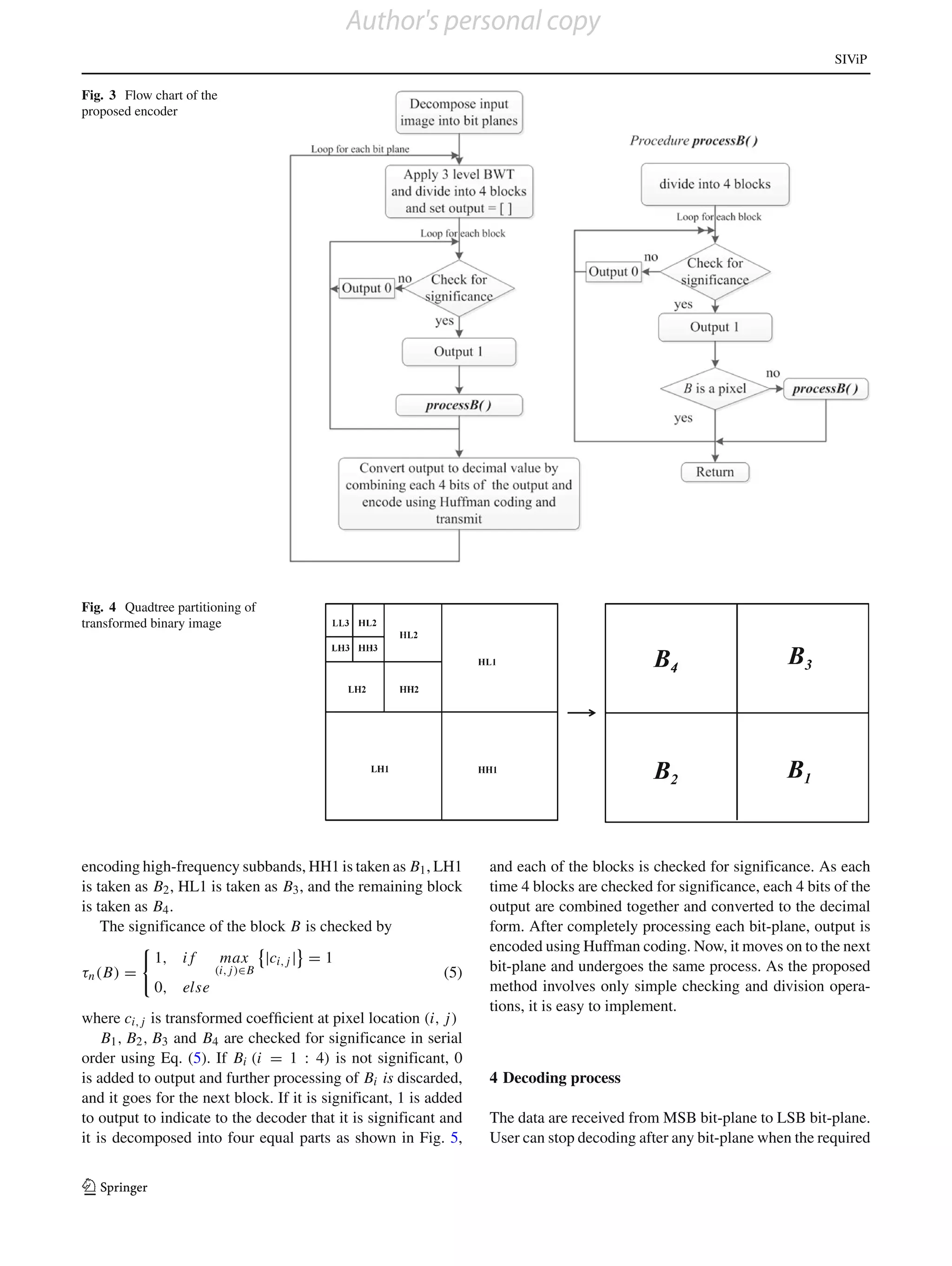
3 The proposed encoder subbands by considering them as parents and then go for
the high-frequency subbands. SPECK [15] uses block-based
In real and integer wavelet transforms, the energy is concen- coding by checking low-frequency subbands first, and then,
trated in low-frequency subbands and a parent–child relation- it checks the high-frequency subbands. The energy clusters
ship exists. So, SPIHT [14] starts from the low-frequency in the binary transform subbands correspond to the spatial
locations associated with edges in the original image. So, the
energy is mainly concentrated in high-frequency subbands.
In the proposed method, higher priority is given for encoding
high-frequency subbands than the low-frequency subbands.
In PPBWC [17], each pixel is checked for significance in
every loop until it becomes significant. In case of ultrasound
images, most of the pixels have very low values, and thus, it
necessitates transmitting more bits for checking the signifi-
cance alone. Thus, it is not efficient. In the proposed method,
block-based coding is used, which requires only 4 bits to
be transmitted if the entire bit-plane is zero. In the proposed
method, more emphasis is given for checking high-frequency
subbands to exploit energy concentration.
The flow chart of the proposed method is given in Fig 3.
The input gray scale image is first decomposed into binary
bit-planes, and then, three-level 2-D BWT is calculated for
each bit-plane starting from the most significant bit-plane
(MSB) to the least significant bit-plane (LSB). Initially, the
binary wavelet transformed image of each bit-plane is divided
Fig. 1 In-place implementation of 1-D BWT for one level into 4 blocks as shown in Fig. 4. To give higher priority for
Fig. 2 One-level 2-D BWT implementation for one bit-plane of gray scale image
123](https://image.slidesharecdn.com/springerbasepaper-130311235124-phpapp01/75/Springer-base-paper-5-2048.jpg)
![Author's personal copy
SIViP
Fig. 11 The output of the
proposed method after each loop
for ultrasound image
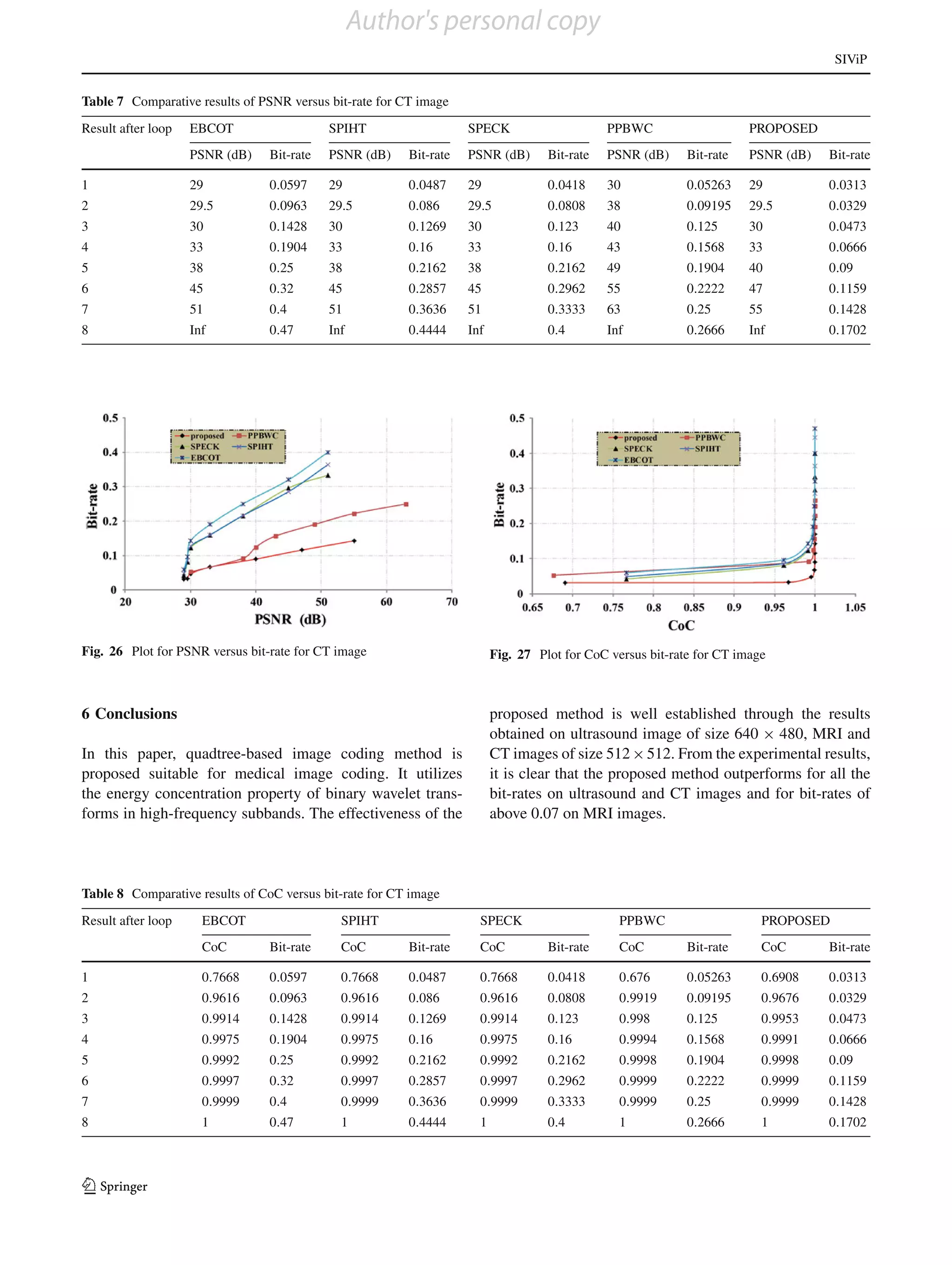
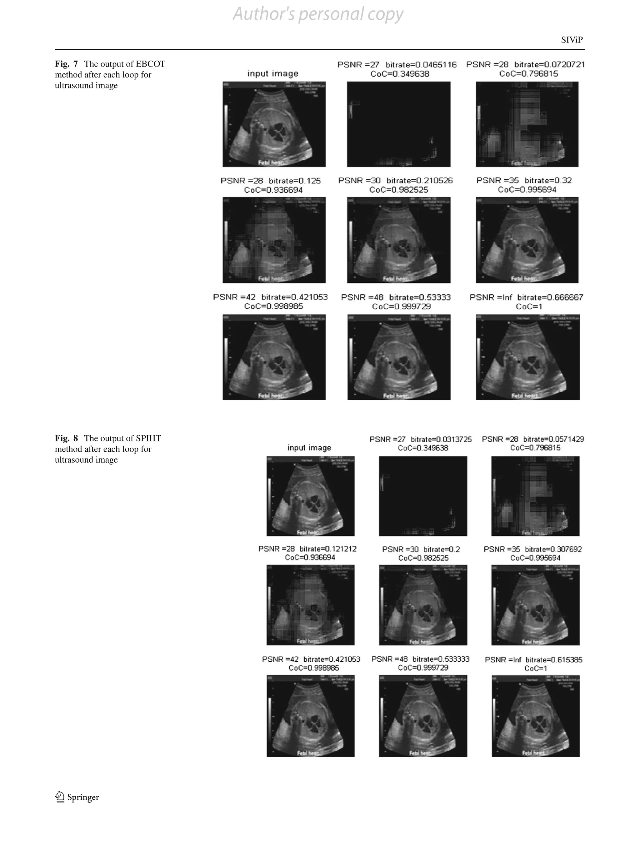
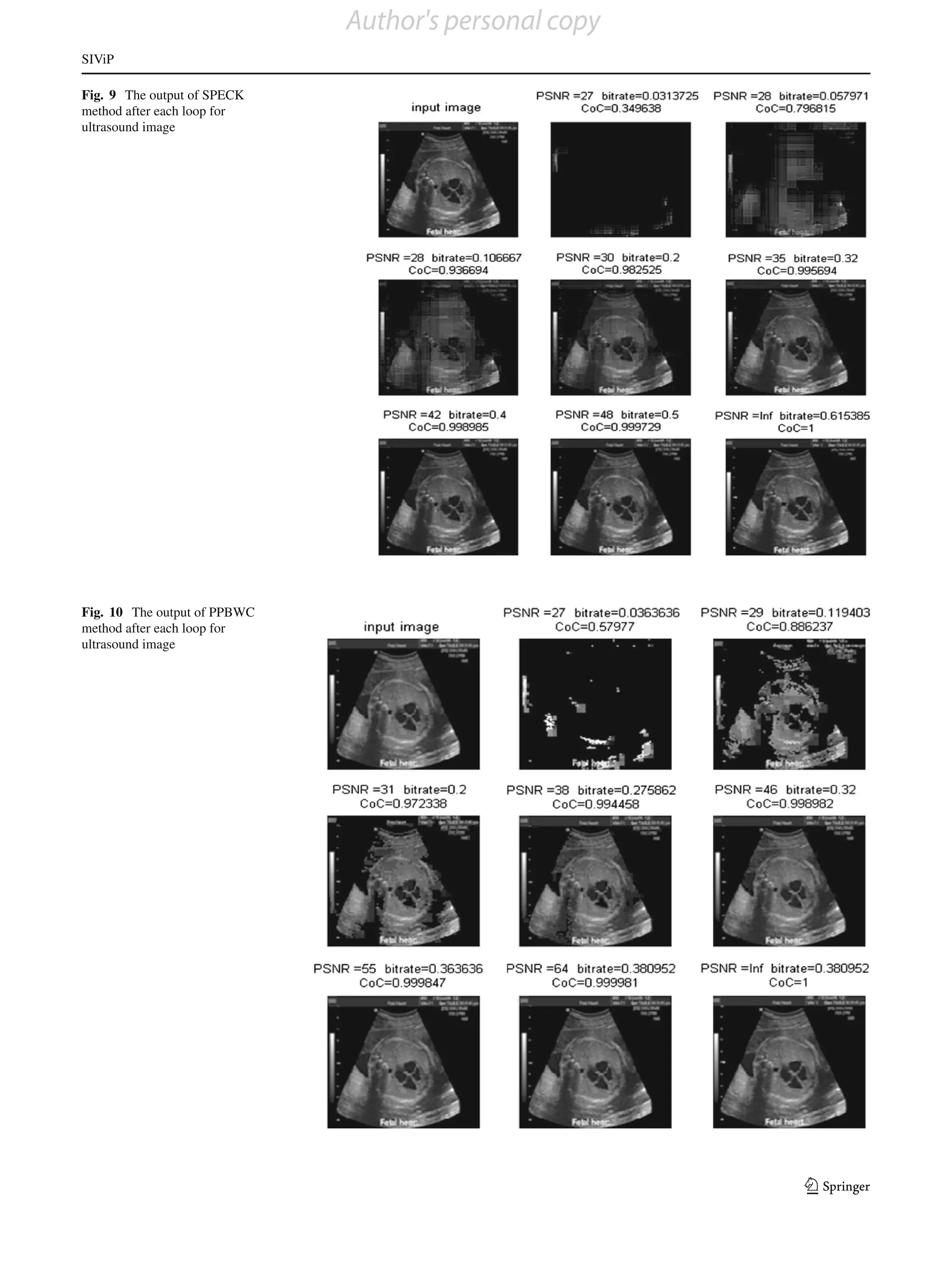
Table 3 Comparative results of PSNR versus bit-rate for ultrasound image
Result after loop EBCOT SPIHT SPECK PPBWC PROPOSED
PSNR (dB) Bit-rate PSNR (dB) Bit-rate PSNR (dB) Bit-rate PSNR (dB) Bit-rate PSNR (dB) Bit-rate
1 27 0.0465 27 0.0313 27 0.0313 27 0.03636 27 0.0313
2 28 0.0720 28 0.0571 28 0.057 29 0.1194 28 0.0792
3 28.5 0.125 28.5 0.1212 28.5 0.1066 31 0.2 32 0.1212
4 30 0.21 30 0.2 30 0.2 38 0.2758 38 0.1632
5 35 0.32 35 0.3076 35 0.32 46 0.32 45 0.2051
6 42 0.42 42 0.4210 42 0.4 55 0.3636 54 0.25
7 48 0.53 48 0.533 48 0.5 64 0.3809 Inf 0.2962
8 Inf 0.666 Inf 0.6153 Inf 0.6153 Inf 0.3892
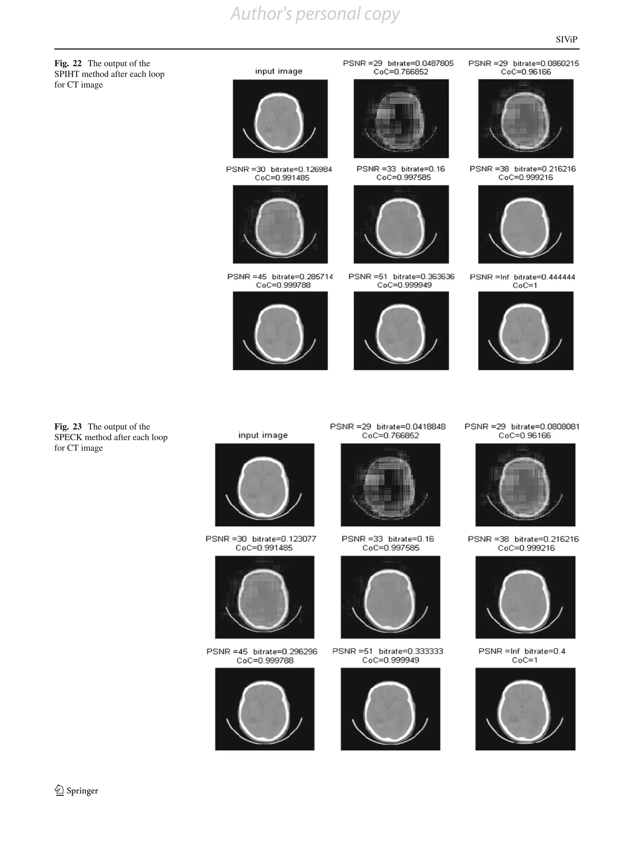
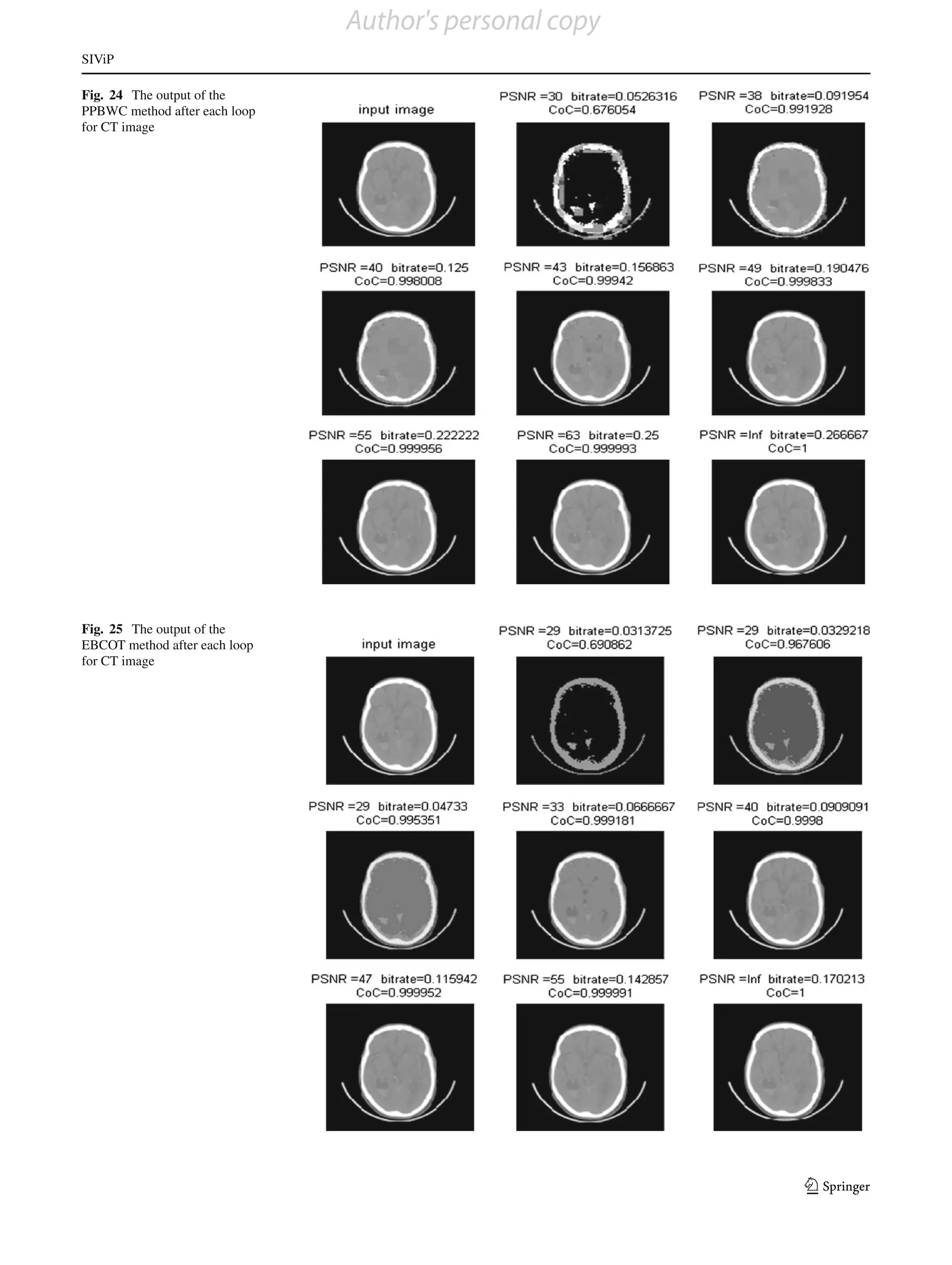
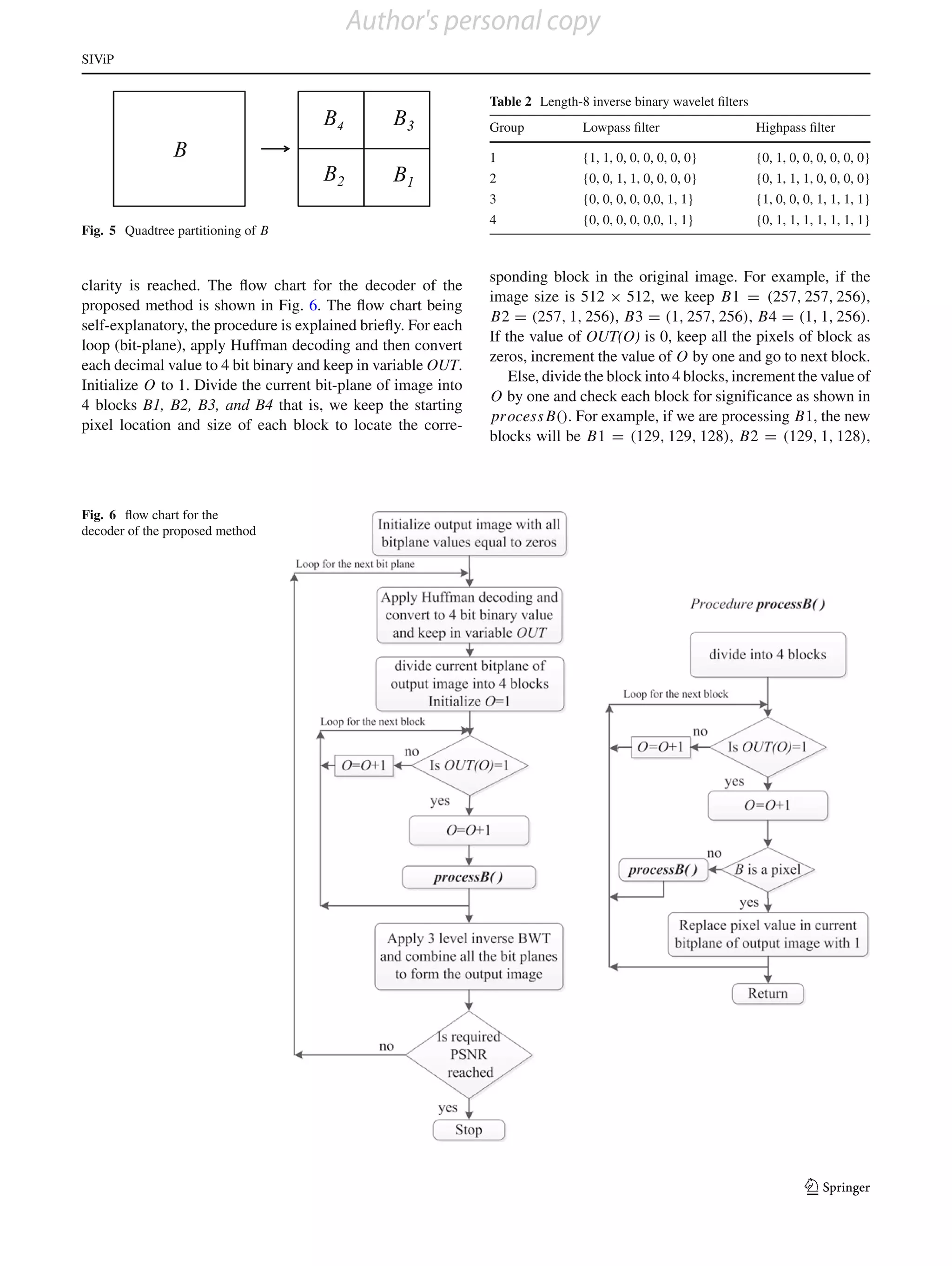
B3 = (1, 129, 128), B4 = (1, 1, 128). While processing a 5 Experimental results and discussions
block if it is reached to single pixel and value of OUT(O)
is 1, then replace that pixel value in the current bit-plane of The performance of the proposed method is evaluated using
the image with 1. After completing the decoding of the entire the bit-rate for the given peak signal-to-noise ratio (PSNR)
bit-plane, apply three-level inverse BWT and combine all the and the correlation coefficient (CoC) [27]. A set of ten MRI,
bit-planes to form gray scale image. Examples of the inverse ten CT images and five ultrasound images are taken for our
binary filters in each group are given in Table 2. Now check experiment. The proposed method is compared with the state-
whether the required clarity is reached. If it has not reached, of-art progressive image coders. SPIHT [14], SPECK [15]
go for the next loop. and EBCOT [16] are implemented using (2, 2) integer wave-
123](https://image.slidesharecdn.com/springerbasepaper-130311235124-phpapp01/75/Springer-base-paper-10-2048.jpg)
![Author's personal copy
SIViP
Fig. 12 Plot for PSNR versus bit-rate for ultrasound image Fig. 13 Plot for bit-rate versus CoC for ultrasound image
let transforms, and the PPBWC [17] is implemented using decoding after any loop depending on the clarity required for
BWT. We got almost similar results for all the images of each making the diagnosis. For lossless reconstruction, the bit-rate
set, and hence, the results for one image from each group are required for the proposed method is only 0.2962 where as it
presented in this section. is 0.3892 for PPBWC and is above 0.6 for the other methods.
For ultrasound images, most of the pixels’ gray levels are From the results and above observations, it is cleared that the
near to zero. Hence, most of the bit-planes consist of only proposed method outperforms all the methods on ultrasound
zeros, and they need not be encoded. In the proposed method, images.
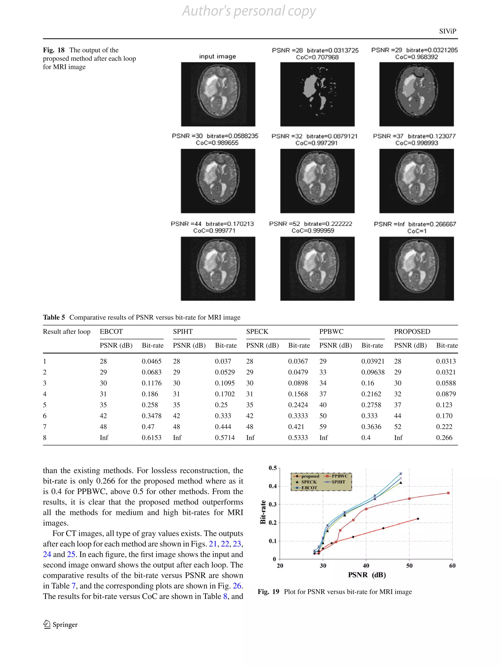
only four bits are transmitted if all the pixels in the bit-plane For MRI images, most of the pixels’ gray levels have
are zero. But, in PPBWC and SPIHT, more bits are to be medium values. Hence, the proposed method needs more
transmitted. Thus, the proposed method requires lesser bit- bits initially giving inferior results for low bit-rate trans-
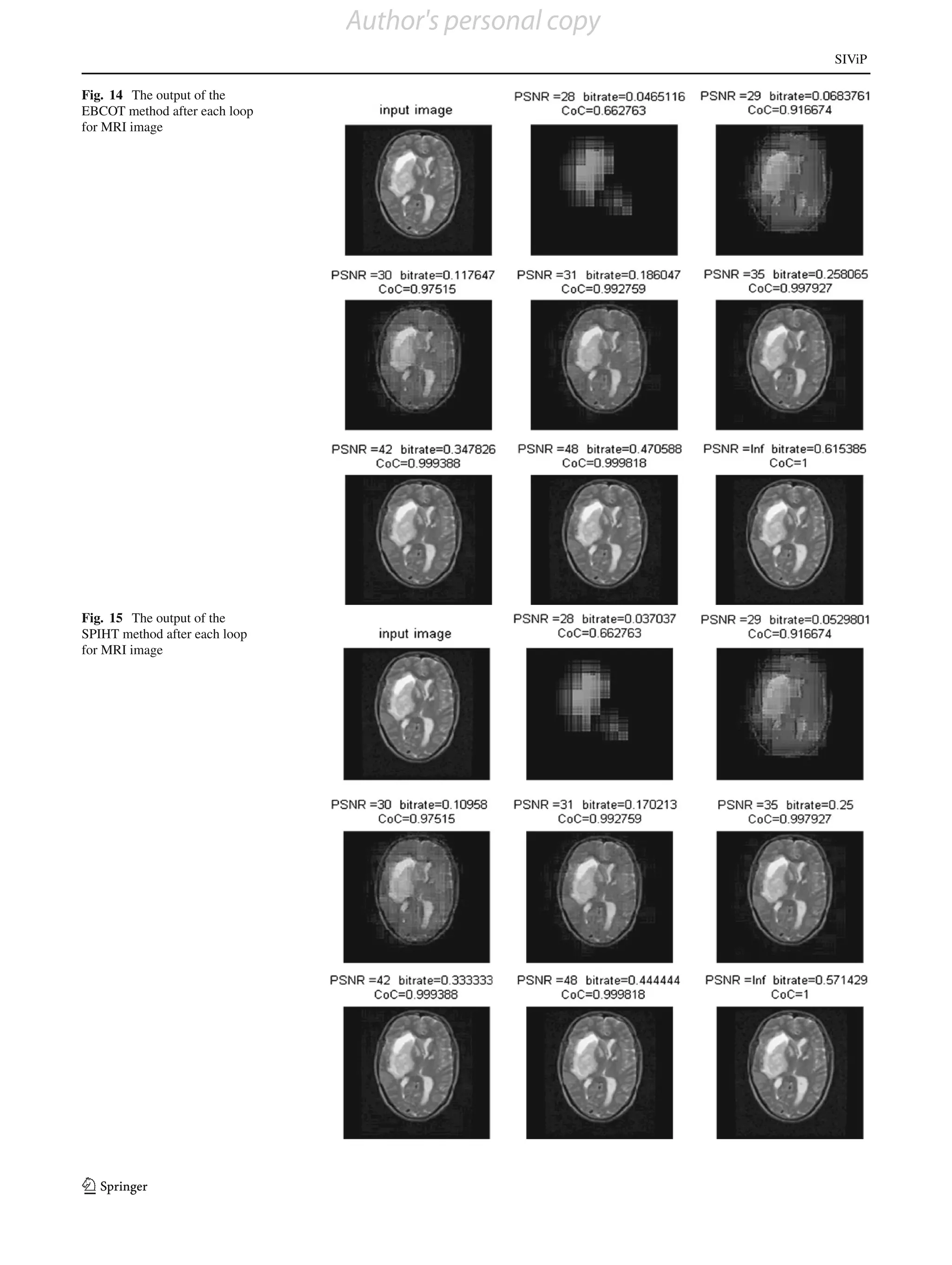
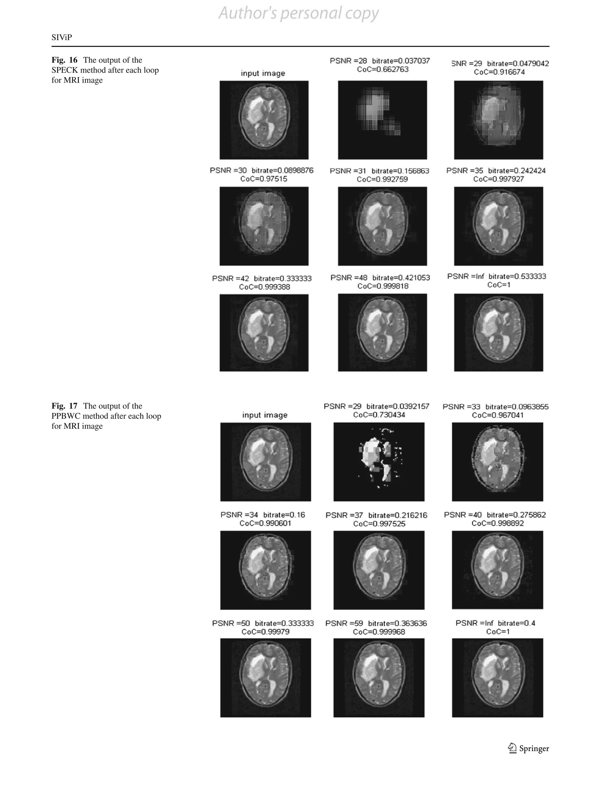
rate for the required PSNR and CoC. The outputs after each mission. But, for medium and high bit-rates, the proposed
loop for each method are shown in Figs. 7, 8, 9, 10 and 11. method gives better results than existing methods. The out-
In each figure, the first image shows the input and second puts after each loop for each method are shown in Figs. 14,
image onward shows the output after each loop. The com- 15, 16, 17 and 18. In each figure, the first image shows the
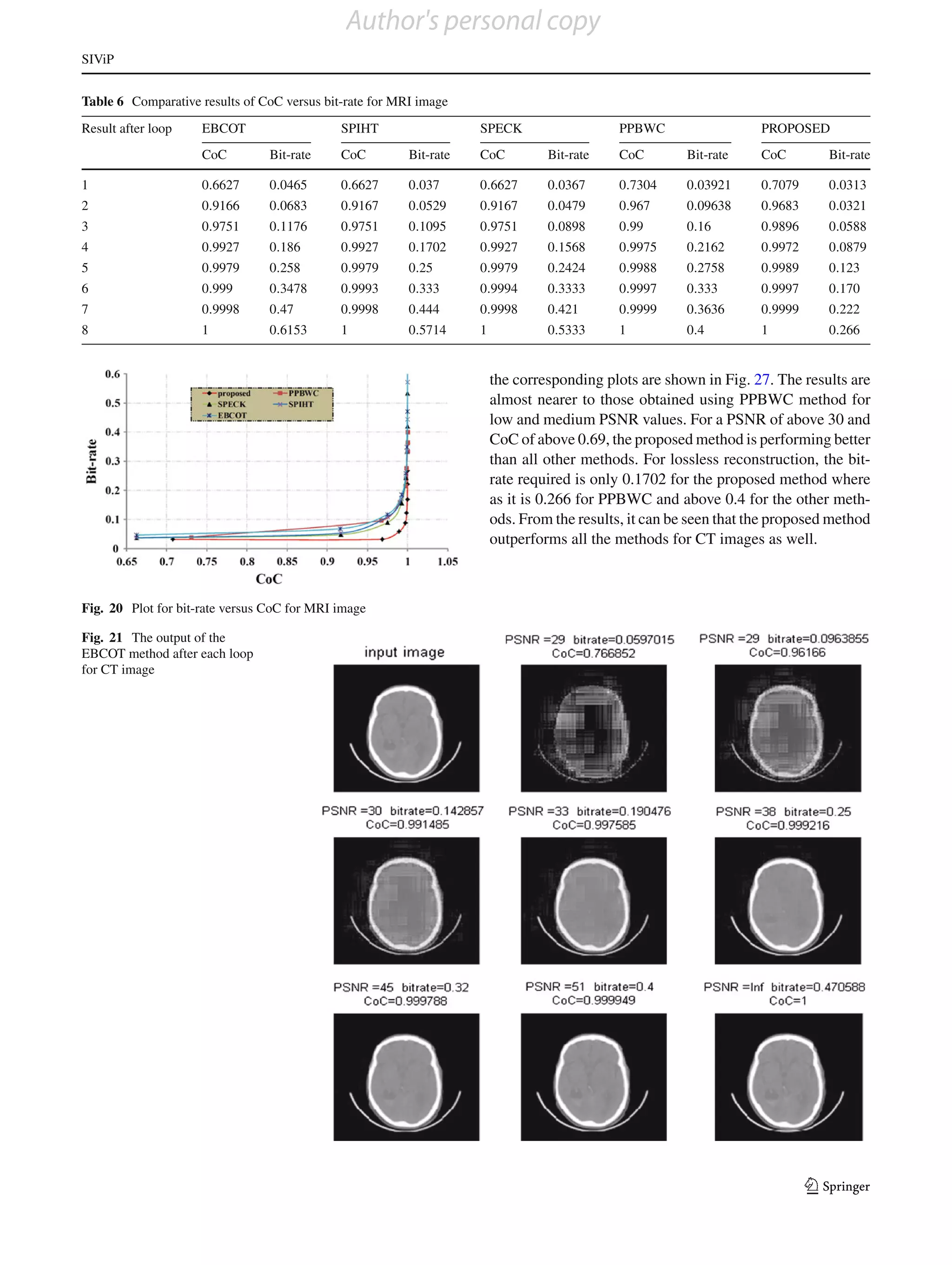
parative results of the bit-rate versus PSNR after each loop input and second image onward shows the output after each
for one image are shown in Table 3, and the corresponding loop. The comparative results of the bit-rate versus PSNR
plots are shown in Fig. 12. The results for bit-rate versus CoC are shown in Table 5, and the corresponding plots are shown
after each loop are shown in Table 4, and the corresponding in Fig. 19. The results for bit-rate versus CoC are shown in
plots are shown in Fig. 13. From the plot, it can be seen that Table 6, and the corresponding plots are shown in Fig. 20.
up to 2nd loop, the proposed method is giving comparable From the plots, it can be seen that for a PSNR of 33 and
results and from the 3rd loop onwards, requires very less CoC of 0.96, the PPBWC is giving better results than the
bit-rate when compared with bit-rates obtainable from other proposed method and for PSNR of above 33 and CoC of
methods for the required PSNR and CoC. The user can stop above 0.96, the proposed method is giving better results
Table 4 Comparative results of CoC versus bit-rate for ultrasound image
Result after loop EBCOT SPIHT SPECK PPBWC PROPOSED
CoC Bit-rate CoC Bit-rate CoC Bit-rate CoC Bit-rate CoC Bit-rate
1 0.3496 0.0465 0.3496 0.3137 0.349 0.0313 0.5797 0.03636 0.5723 0.3137
2 0.7968 0.0720 0.7968 0.0571 0.7968 0.057 0.8862 0.1194 0.9711 0.0792
3 0.9366 0.125 0.9366 0.1212 0.9366 0.1066 0.9723 0.2 0.9931 0.1212
4 0.9820 0.21 0.9825 0.2 0.9825 0.2 0.9944 0.2758 0.9985 0.1632
5 0.9956 0.32 0.99 0.3076 0.9956 0.32 0.998 0.32 0.999 0.2051
6 0.998 0.42 0.9989 0.4210 0.9989 0.4 0.9998 0.3636 0.9999 0.25
7 0.999 0.53 0.999 0.533 0.999 0.5 0.9999 0.3809 1 0.2962
8 1 0.666 1 0.6153 1 0.6153 1 0.3892
123](https://image.slidesharecdn.com/springerbasepaper-130311235124-phpapp01/75/Springer-base-paper-11-2048.jpg)