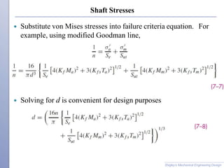
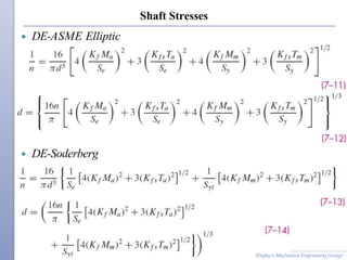
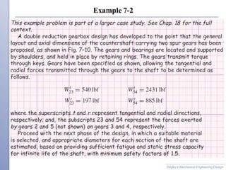
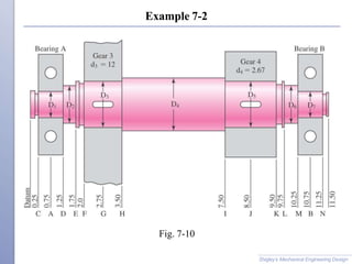
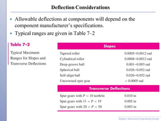
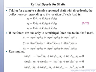
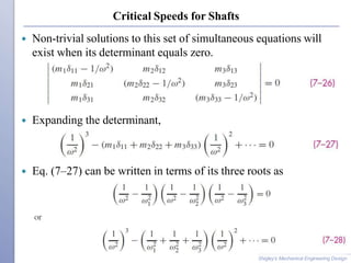
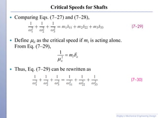
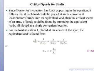
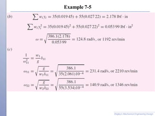
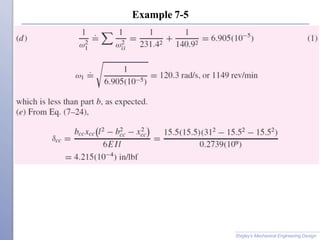
This document summarizes key considerations for designing shafts and shaft components. It discusses material selection, geometric layout, stress and strength analysis, deflection, and vibration due to natural frequency. Key steps in shaft design include considering the axial layout of components, supporting axial loads, providing for torque transmission, and enabling assembly and disassembly. Critical locations on shafts are evaluated for stress, and equations are provided to calculate stresses from bending, torsion, and combined loads. Deflection and critical speeds are also addressed. Examples demonstrate applying the summarized design methodology.
diploma mechanical engineering
,
mechanical engineering
,
square threads
,
types and forms of threads
,
overhauling of screw threads
,
self locking of screw threads
,
design of machine elements
,
machine design
Chess pieces made through cnc lathe programming . It includes all the chess pieces except knight with their cad drawing and their programes based on cnc codding .
introduction, types of scissor lift, advantages and disadvantages design of different components and calculation based of selected material. generated 3d model in solidworks.
The project presents a two speed transmission. Design requirements for the transmission state that it must have two forward gears and two reverse gears, be compact, be quiet, and have a collinear design. Also, the design must last for 1600 hours at each gear for a combined life of 6400 hours between 750 and 1250 rotations per minute (RPM) with a power input of 32 horsepower. The output shaft must rotate at 85% (±1%) and 65% (±1%) of the input speed in the input direction, and 60% (±1%) and 50% (±1%) of the input speed in the opposing direction. The design chosen consists of an input shaft, counter shaft, idler shaft, and an output shaft assemblies which were all designed using helical gears, tapered roller bearings, and radial ball bearings. Validation of the gears, bearings, and shafts were done using RomaxDesigner software. Analysis of the duty cycle summary for the final design shows design failure shortly after the required combined life of 6400 hours.
Design of Stage Progressive Die for a Sheet Metal Component STAY CURIOUS
Progressive die stamping is a metal forming process widely used to produce parts for various industries, such as automotive, electronics and appliances. Progressive die stamping consists of several individual work stations, each of which performs one or more different operations on the part.
Deflection of curved beam |Strength of Material LaboratorySaif al-din ali
SAIF ALDIN ALI MADIN
سيف الدين علي ماضي
S96aif@gmail.com
Experiment Name:- Deflection of curved beam
2. Introduction
The deflection of a beam or bars must be often be limited in order to provide
integrity and stability of structure or machine. Plus, code restrictions often require
these members not vibrate or deflect severely in order to safely support their
intended loading.
This experiment helps us to show some kind of deflection and how to calculate the
deflection value by using Castigliano’s Theorem and make a comparison between
result of the experiment and the theory.
Basic types of screw fasteners, Bolts of uniform
strength, I.S.O. Metric screw threads, Bolts under
tension, eccentrically loaded bolted joint in shear,
Eccentric load perpendicular and parallel to axis of
bolt, Eccentric load on circular base, design of Turn
Buckle.
GEOMETRIC OPTIMIZATION OF CRANK SHAFT FOR OPTIMUM DESIGN AND IMPROVEMENT OF LIFEIjripublishers Ijri
Crankshaft is a component in an engine which converts the reciprocating motion of the piston to the rotary motion. Design
of a crankshaft of Honda engine, it is assembled by the connecting rod and piston components in Pro engineering.
The designed model of engine crankshaft is analyzed in pro engineering by using its mechanism. Piston generates the
forces due to the combustion. These forces acting on the piston are analyzed by using their mechanisms with respect
to crank angle.
An academic presentation that highlights main shafts applications and conduct stress and fatigue analysis in shafts as shafts being an essential part in the automotive manufacturing
Design of half shaft and wheel hub assembly for racing carRavi Shekhar
The Half - Shaft and Wheel Hub of Formula One racing car was designed taking into consideration one of the popular model of Redbull racing car. The various dimension of shaft and hub were altered to attain maximum factor of safety.
IJRET : International Journal of Research in Engineering and Technology is an international peer reviewed, online journal published by eSAT Publishing House for the enhancement of research in various disciplines of Engineering and Technology. The aim and scope of the journal is to provide an academic medium and an important reference for the advancement and dissemination of research results that support high-level learning, teaching and research in the fields of Engineering and Technology. We bring together Scientists, Academician, Field Engineers, Scholars and Students of related fields of Engineering and Technology.
MULTI CAVITY DIE PREPARATION, ANALYSIS AND MANUFACTURING PROCESS OF DIESEL EN...Ijripublishers Ijri
A piston is a component of reciprocating engines, reciprocating pumps, gas compressors and pneumatic cylinders,
among other similar mechanisms. It is the moving component that is contained by a cylinder and is made gas-tight by
piston rings. The piston transforms the energy of the expanding gasses into mechanical energy. The piston rides in the
cylinder liner or sleeve. Pistons are commonly made of aluminum or cast iron alloys.
Design analysis of the roll cage for all terrain vehicleeSAT Journals
Abstract We have tried to design an all terrain vehicle that meets international standards and is also cost effective at the same time. We have focused on every point of roll cage to improve the performance of vehicle without failure of roll cage. We began the task of designing by conducting extensive research of ATV roll cage through finite element analysis. A roll cage is a skeleton of an ATV. The roll cage not only forms the structural base but also a 3-D shell surrounding the occupant which protects the occupant in case of impact and roll over incidents. The roll cage also adds to the aesthetics of a vehicle. The design and development comprises of material selection, chassis and frame design, cross section determination, determining strength requirements of roll cage, stress analysis and simulations to test the ATV against failure. Keywords: Roll cage, material, finite element analysis, strength
Immunizing Image Classifiers Against Localized Adversary Attacksgerogepatton
This paper addresses the vulnerability of deep learning models, particularly convolutional neural networks
(CNN)s, to adversarial attacks and presents a proactive training technique designed to counter them. We
introduce a novel volumization algorithm, which transforms 2D images into 3D volumetric representations.
When combined with 3D convolution and deep curriculum learning optimization (CLO), itsignificantly improves
the immunity of models against localized universal attacks by up to 40%. We evaluate our proposed approach
using contemporary CNN architectures and the modified Canadian Institute for Advanced Research (CIFAR-10
and CIFAR-100) and ImageNet Large Scale Visual Recognition Challenge (ILSVRC12) datasets, showcasing
accuracy improvements over previous techniques. The results indicate that the combination of the volumetric
input and curriculum learning holds significant promise for mitigating adversarial attacks without necessitating
adversary training.
Welcome to WIPAC Monthly the magazine brought to you by the LinkedIn Group Water Industry Process Automation & Control.
In this month's edition, along with this month's industry news to celebrate the 13 years since the group was created we have articles including
A case study of the used of Advanced Process Control at the Wastewater Treatment works at Lleida in Spain
A look back on an article on smart wastewater networks in order to see how the industry has measured up in the interim around the adoption of Digital Transformation in the Water Industry.
Quality defects in TMT Bars, Possible causes and Potential Solutions.PrashantGoswami42
Maintaining high-quality standards in the production of TMT bars is crucial for ensuring structural integrity in construction. Addressing common defects through careful monitoring, standardized processes, and advanced technology can significantly improve the quality of TMT bars. Continuous training and adherence to quality control measures will also play a pivotal role in minimizing these defects.
CFD Simulation of By-pass Flow in a HRSG module by R&R Consult.pptxR&R Consult
CFD analysis is incredibly effective at solving mysteries and improving the performance of complex systems!
Here's a great example: At a large natural gas-fired power plant, where they use waste heat to generate steam and energy, they were puzzled that their boiler wasn't producing as much steam as expected.
R&R and Tetra Engineering Group Inc. were asked to solve the issue with reduced steam production.
An inspection had shown that a significant amount of hot flue gas was bypassing the boiler tubes, where the heat was supposed to be transferred.
R&R Consult conducted a CFD analysis, which revealed that 6.3% of the flue gas was bypassing the boiler tubes without transferring heat. The analysis also showed that the flue gas was instead being directed along the sides of the boiler and between the modules that were supposed to capture the heat. This was the cause of the reduced performance.
Based on our results, Tetra Engineering installed covering plates to reduce the bypass flow. This improved the boiler's performance and increased electricity production.
It is always satisfying when we can help solve complex challenges like this. Do your systems also need a check-up or optimization? Give us a call!
Work done in cooperation with James Malloy and David Moelling from Tetra Engineering.
More examples of our work https://www.r-r-consult.dk/en/cases-en/
Saudi Arabia stands as a titan in the global energy landscape, renowned for its abundant oil and gas resources. It's the largest exporter of petroleum and holds some of the world's most significant reserves. Let's delve into the top 10 oil and gas projects shaping Saudi Arabia's energy future in 2024.
Sachpazis:Terzaghi Bearing Capacity Estimation in simple terms with Calculati...Dr.Costas Sachpazis
Terzaghi's soil bearing capacity theory, developed by Karl Terzaghi, is a fundamental principle in geotechnical engineering used to determine the bearing capacity of shallow foundations. This theory provides a method to calculate the ultimate bearing capacity of soil, which is the maximum load per unit area that the soil can support without undergoing shear failure. The Calculation HTML Code included.
Democratizing Fuzzing at Scale by Abhishek Aryaabh.arya
Presented at NUS: Fuzzing and Software Security Summer School 2024
This keynote talks about the democratization of fuzzing at scale, highlighting the collaboration between open source communities, academia, and industry to advance the field of fuzzing. It delves into the history of fuzzing, the development of scalable fuzzing platforms, and the empowerment of community-driven research. The talk will further discuss recent advancements leveraging AI/ML and offer insights into the future evolution of the fuzzing landscape.
Forklift Classes Overview by Intella PartsIntella Parts
Discover the different forklift classes and their specific applications. Learn how to choose the right forklift for your needs to ensure safety, efficiency, and compliance in your operations.
For more technical information, visit our website https://intellaparts.com
TECHNICAL TRAINING MANUAL GENERAL FAMILIARIZATION COURSEDuvanRamosGarzon1
AIRCRAFT GENERAL
The Single Aisle is the most advanced family aircraft in service today, with fly-by-wire flight controls.
The A318, A319, A320 and A321 are twin-engine subsonic medium range aircraft.
The family offers a choice of engines
COLLEGE BUS MANAGEMENT SYSTEM PROJECT REPORT.pdfKamal Acharya
The College Bus Management system is completely developed by Visual Basic .NET Version. The application is connect with most secured database language MS SQL Server. The application is develop by using best combination of front-end and back-end languages. The application is totally design like flat user interface. This flat user interface is more attractive user interface in 2017. The application is gives more important to the system functionality. The application is to manage the student’s details, driver’s details, bus details, bus route details, bus fees details and more. The application has only one unit for admin. The admin can manage the entire application. The admin can login into the application by using username and password of the admin. The application is develop for big and small colleges. It is more user friendly for non-computer person. Even they can easily learn how to manage the application within hours. The application is more secure by the admin. The system will give an effective output for the VB.Net and SQL Server given as input to the system. The compiled java program given as input to the system, after scanning the program will generate different reports. The application generates the report for users. The admin can view and download the report of the data. The application deliver the excel format reports. Because, excel formatted reports is very easy to understand the income and expense of the college bus. This application is mainly develop for windows operating system users. In 2017, 73% of people enterprises are using windows operating system. So the application will easily install for all the windows operating system users. The application-developed size is very low. The application consumes very low space in disk. Therefore, the user can allocate very minimum local disk space for this application.
Automobile Management System Project Report.pdfKamal Acharya
The proposed project is developed to manage the automobile in the automobile dealer company. The main module in this project is login, automobile management, customer management, sales, complaints and reports. The first module is the login. The automobile showroom owner should login to the project for usage. The username and password are verified and if it is correct, next form opens. If the username and password are not correct, it shows the error message.
When a customer search for a automobile, if the automobile is available, they will be taken to a page that shows the details of the automobile including automobile name, automobile ID, quantity, price etc. “Automobile Management System” is useful for maintaining automobiles, customers effectively and hence helps for establishing good relation between customer and automobile organization. It contains various customized modules for effectively maintaining automobiles and stock information accurately and safely.
When the automobile is sold to the customer, stock will be reduced automatically. When a new purchase is made, stock will be increased automatically. While selecting automobiles for sale, the proposed software will automatically check for total number of available stock of that particular item, if the total stock of that particular item is less than 5, software will notify the user to purchase the particular item.
Also when the user tries to sale items which are not in stock, the system will prompt the user that the stock is not enough. Customers of this system can search for a automobile; can purchase a automobile easily by selecting fast. On the other hand the stock of automobiles can be maintained perfectly by the automobile shop manager overcoming the drawbacks of existing system.
Vaccine management system project report documentation..pdfKamal Acharya
The Division of Vaccine and Immunization is facing increasing difficulty monitoring vaccines and other commodities distribution once they have been distributed from the national stores. With the introduction of new vaccines, more challenges have been anticipated with this additions posing serious threat to the already over strained vaccine supply chain system in Kenya.
3. Shaft Design
Shigley’s Mechanical Engineering Design
Material Selection
Geometric Layout
Stress and strength
◦ Static strength
◦ Fatigue strength
Deflection and rigidity
◦ Bending deflection
◦ Torsional deflection
◦ Slope at bearings and shaft-supported elements
◦ Shear deflection due to transverse loading of short shafts
Vibration due to natural frequency
4. Shaft Materials
Deflection primarily controlled by geometry, not material
Stress controlled by geometry, not material
Strength controlled by material property
Shigley’s Mechanical Engineering Design
5. Shaft Materials
Shafts are commonly made from low carbon, CD or HR steel,
such as ANSI 1020–1050 steels.
Fatigue properties don’t usually benefit much from high alloy
content and heat treatment.
Surface hardening usually only used when the shaft is being
used as a bearing surface.
Shigley’s Mechanical Engineering Design
6. Shaft Materials
Cold drawn steel typical for d < 3 in.
HR steel common for larger sizes. Should be machined all over.
Low production quantities
◦ Lathe machining is typical
◦ Minimum material removal may be design goal
High production quantities
◦ Forming or casting is common
◦ Minimum material may be design goal
Shigley’s Mechanical Engineering Design
7. Shaft Layout
Issues to consider for
shaft layout
◦ Axial layout of
components
◦ Supporting axial
loads
◦ Providing for torque
transmission
◦ Assembly and
Disassembly
Fig. 7-1
Shigley’s Mechanical Engineering Design
9. Supporting Axial Loads
Axial loads must be supported through a bearing to the frame.
Generally best for only one bearing to carry axial load to
shoulder
Allows greater tolerances and prevents binding
Fig. 7-3
Shigley’s Mechanical Engineering Design
Fig. 7-4
10. Providing for Torque Transmission
Common means of transferring torque to shaft
◦ Keys
◦ Splines
◦ Setscrews
◦ Pins
◦ Press or shrink fits
◦ Tapered fits
Keys are one of the most effective
◦ Slip fit of component onto shaft for easy assembly
◦ Positive angular orientation of component
◦ Can design key to be weakest link to fail in case of overload
Shigley’s Mechanical Engineering Design
13. Shaft Design for Stress
Stresses are only evaluated at critical locations
Critical locations are usually
◦ On the outer surface
◦ Where the bending moment is large
◦ Where the torque is present
◦ Where stress concentrations exist
Shigley’s Mechanical Engineering Design
14. Shaft Stresses
Standard stress equations can be customized for shafts for
convenience
Axial loads are generally small and constant, so will be ignored
in this section
Standard alternating and midrange stresses
Customized for round shafts
Shigley’s Mechanical Engineering Design
15. Shaft Stresses
Combine stresses into von Mises stresses
Shigley’s Mechanical Engineering Design
16. Shaft Stresses
Substitute von Mises stresses into failure criteria equation. For
example, using modified Goodman line,
Solving for d is convenient for design purposes
Shigley’s Mechanical Engineering Design
17. Shaft Stresses
Shigley’s Mechanical Engineering Design
Similar approach can be taken with any of the fatigue failure
criteria
Equations are referred to by referencing both the Distortion
Energy method of combining stresses and the fatigue failure
locus name. For example, DE-Goodman, DE-Gerber, etc.
In analysis situation, can either use these customized equations
for factor of safety, or can use standard approach from Ch. 6.
In design situation, customized equations for d are much more
convenient.
20. Shaft Stresses for Rotating Shaft
For rotating shaft with steady bending and torsion
◦ Bending stress is completely reversed, since a stress element
on the surface cycles from equal tension to compression
during each rotation
◦ Torsional stress is steady
◦ Previous equations simplify with Mm and Ta equal to 0
Shigley’s Mechanical Engineering Design
21. Checking for Yielding in Shafts
Always necessary to consider static failure, even in fatigue
situation
Soderberg criteria inherently guards against yielding
ASME-Elliptic criteria takes yielding into account, but is not
entirely conservative
Gerber and modified Goodman criteria require specific check for
yielding
Shigley’s Mechanical Engineering Design
22. Checking for Yielding in Shafts
Use von Mises maximum stress to check for yielding,
Alternate simple check is to obtain conservative estimate of 'max
by summing 'a and 'm
m
ax a
m
Shigley’s Mechanical Engineering Design
28. Estimating Stress Concentrations
Stress analysis for shafts is highly dependent on stress
concentrations.
Stress concentrations depend on size specifications, which are
not known the first time through a design process.
Standard shaft elements such as shoulders and keys have
standard proportions, making it possible to estimate stress
concentrations factors before determining actual sizes.
Shigley’s Mechanical Engineering Design
30. Reducing Stress Concentration at Shoulder Fillet
Bearings often require relatively sharp fillet radius at shoulder
If such a shoulder is the location of the critical stress, some
manufacturing techniques are available to reduce the stress
concentration
(a) Large radius undercut into shoulder
(b) Large radius relief groove into back of shoulder
(c) Large radius relief groove into small diameter of shaft
Fig. 7-9
Shigley’s Mechanical Engineering Design
45. Deflection Considerations
Deflection analysis at a single point of interest requires complete
geometry information for the entire shaft.
For this reason, a common approach is to size critical locations
for stress, then fill in reasonable size estimates for other
locations, then perform deflection analysis.
Deflection of the shaft, both linear and angular, should be
checked at gears and bearings.
Shigley’s Mechanical Engineering Design
46. Deflection Considerations
Allowable deflections at components will depend on the
component manufacturer’s specifications.
Typical ranges are given in Table 7–2
Shigley’s Mechanical Engineering Design
47. Deflection Considerations
Deflection analysis is straightforward, but lengthy and tedious to
carry out manually.
Each point of interest requires entirely new deflection analysis.
Consequently, shaft deflection analysis is almost always done
with the assistance of software.
Options include specialized shaft software, general beam
deflection software, and finite element analysis software.
Shigley’s Mechanical Engineering Design
53. Adjusting Diameters for Allowable Deflections
If any deflection is larger than allowed, since I is proportional to
d4, a new diameter can be found from
Similarly, for slopes,
Determine the largest dnew/dold ratio, then multiply all diameters
by this ratio.
The tight constraint will be just right, and the others will be
loose.
Shigley’s Mechanical Engineering Design
55. Angular Deflection of Shafts
For stepped shaft with individual cylinder length li and torque Ti,
the angular deflection can be estimated from
For constant torque throughout homogeneous material
Experimental evidence shows that these equations slightly
underestimate the angular deflection.
Torsional stiffness of a stepped shaft is
Shigley’s Mechanical Engineering Design
56. Critical Speeds for Shafts
A shaft with mass has a critical speed at which its deflections
become unstable.
Components attached to the shaft have an even lower critical
speed than the shaft.
Designers should ensure that the lowest critical speed is at least
twice the operating speed.
Shigley’s Mechanical Engineering Design
57. Critical Speeds for Shafts
For a simply supported shaft of uniform diameter, the first
critical speed is
For an ensemble of attachments, Rayleigh’s method for lumped
masses gives
Shigley’s Mechanical Engineering Design
58. Critical Speeds for Shafts
Eq. (7–23) can be applied to the shaft itself by partitioning the
shaft into segments.
Fig. 7–12
Shigley’s Mechanical Engineering Design
59. Critical Speeds for Shafts
An influence coefficient is the transverse deflection at location I
due to a unit load at location j.
From Table A–9–6 for a simply supported beam with a single
unit load
Shigley’s Mechanical Engineering Design
Fig. 7–13
60. Critical Speeds for Shafts
Taking for example a simply supported shaft with three loads, the
deflections corresponding to the location of each load is
If the forces are due only to centrifugal force due to the shaft mass,
Rearranging,
Shigley’s Mechanical Engineering Design
61. Critical Speeds for Shafts
Non-trivial solutions to this set of simultaneous equations will
exist when its determinant equals zero.
Expanding the determinant,
Eq. (7–27) can be written in terms of its three roots as
Shigley’s Mechanical Engineering Design
62. Critical Speeds for Shafts
Comparing Eqs. (7–27) and (7–28),
Define ii as the critical speed if mi is acting alone.
From Eq. (7–29),
Thus, Eq. (7–29) can be rewritten as
2 i ii
ii
1
m
Shigley’s Mechanical Engineering Design
63. Critical Speeds for Shafts
Note that
The first critical speed can be approximated from Eq. (7–30) as
Extending this idea to an n-body shaft, we obtain Dunkerley’s
equation,
Shigley’s Mechanical Engineering Design
64. Critical Speeds for Shafts
Since Dunkerley’s equation has loads appearing in the equation, it
follows that if each load could be placed at some convenient
location transformed into an equivalent load, then the critical speed
of an array of loads could be found by summing the equivalent
loads, all placed at a single convenient location.
For the load at station 1, placed at the center of the span, the
equivalent load is found from
Shigley’s Mechanical Engineering Design
72. Setscrews
Setscrews resist axial and rotational motion
They apply a compressive force to create friction
The tip of the set screw may also provide a slight penetration
Various tips are available
Fig. 7–15
Shigley’s Mechanical Engineering Design
73.
74. Setscrews
Resistance to axial
motion of collar or
hub relative to shaft
is called holding
power
Typical values listed
in Table 7–4 apply to
axial and torsional
resistance
Typical factors of
safety are 1.5 to 2.0
for static, and 4 to 8
for dynamic loads
Length should be
about half the shaft
diameter
Shigley’s Mechanical Engineering Design
75. Keys and Pins
Used to secure
rotating elements and
to transmit torque
Fig. 7–16
Shigley’s Mechanical Engineering Design
76.
77. Tapered Pins
Taper pins are sized by diameter at large end
Small end diameter is
Table 7–5 shows some standard sizes in inches
Table 7–5 Shigley’s Mechanical Engineering Design
78. Keys
Keys come in
standard square
and rectangular
sizes
Shaft diameter
determines key
size
Table 7–6 Shigley’s Mechanical Engineering Design
79. Keys
Failure of keys is by either direct shear or bearing stress
Key length is designed to provide desired factor of safety
Factor of safety should not be excessive, so the inexpensive key
is the weak link
Key length is limited to hub length
Key length should not exceed 1.5 times shaft diameter to avoid
problems from twisting
Multiple keys may be used to carry greater torque, typically
oriented 90º from one another
Stock key material is typically low carbon cold-rolled steel,
with dimensions slightly under the nominal dimensions to
easily fit end-milled keyway
A setscrew is sometimes used with a key for axial positioning,
and to minimize rotational backlash
Shigley’s Mechanical Engineering Design
80. Gib-head Key
Gib-head key is tapered so that when firmly driven it prevents
axial motion
Head makes removal easy
Projection of head may be hazardous
Fig. 7–17
Shigley’s Mechanical Engineering Design
81. Woodruff Key
Woodruff keys have deeper penetration
Useful for smaller shafts to prevent key from rolling
When used near a shoulder, the keyway stress concentration
interferes less with shoulder than square keyway
Fig. 7–17
Shigley’s Mechanical Engineering Design
84. Stress Concentration Factors for Keys
For keyseats cut by standard end-mill cutters, with a ratio of
r/d = 0.02, Peterson’s charts give
◦ Kt = 2.14 for bending
◦ Kt = 2.62 for torsion without the key in place
◦ Kt = 3.0 for torsion with the key in place
Keeping the end of the keyseat at least a distance of d/10 from
the shoulder fillet will prevent the two stress concentrations
from combining.
Shigley’s Mechanical Engineering Design
88. Retaining Rings
Retaining rings are often used instead of a shoulder to provide
axial positioning
Fig. 7–18
Shigley’s Mechanical Engineering Design
89. Retaining Rings
Retaining ring must seat well in bottom of groove to support
axial loads against the sides of the groove.
This requires sharp radius in bottom of groove.
Stress concentrations for flat-bottomed grooves are available in
TableA–15–16 and A–15–17.
Typical stress concentration factors are high, around 5 for
bending and axial, and 3 for torsion
Shigley’s Mechanical Engineering Design
90. Limits and Fits
Shaft diameters need to be sized to “fit” the shaft components
(e.g. gears, bearings, etc.)
Need ease of assembly
Need minimum slop
May need to transmit torque through press fit
Shaft design requires only nominal shaft diameters
Precise dimensions, including tolerances, are necessary to
finalize design
Shigley’s Mechanical Engineering Design
91. Tolerances
Close tolerances generally
increase cost
◦ Require additional
processing steps
◦ Require additional
inspection
◦ Require machines with
lower production rates
Fig. 1–2
Shigley’s Mechanical Engineering Design
92. Standards for Limits and Fits
Two standards for limits and fits in use in United States
◦ U.S. Customary (1967)
Metric (1978)
Metric version will be presented, with a set of inch conversions
Shigley’s Mechanical Engineering Design
93. Nomenclature for Cylindrical Fit
Upper case letters
refer to hole
Lower case letters
refer to shaft
Basic size is the
nominal diameter and
is same for both parts,
D=d
Tolerance is the
difference between
maximum and
minimum size
Deviation is the
difference between a
size and the basic size Fig. 7–20
Shigley’s Mechanical Engineering Design
94. Tolerance Grade Number
Tolerance is the difference between maximum and minimum size
International tolerance grade numbers designate groups of
tolerances such that the tolerances for a particular IT number
have the same relative level of accuracy but vary depending on
the basic size
IT grades range from IT0 to IT16, but only IT6 to IT11 are
generally needed
Specifications for IT grades are listed in Table A–11 for metric
series and A–13 for inch series
Shigley’s Mechanical Engineering Design
96. Tolerance Grades – Inch Series
Table A–13
Shigley’s Mechanical Engineering Design
97. Deviations
Deviation is the algebraic difference between a size and the basic
size
Upper deviation is the algebraic difference between the maximum
limit and the basic size
Lower deviation is the algebraic difference between the minimum
limit and the basic size
Fundamental deviation is either the upper or lower deviation that
is closer to the basic size
Letter codes are used to designate a similar level of clearance or
interference for different basic sizes
Shigley’s Mechanical Engineering Design
98. Fundamental Deviation Letter Codes
Shafts with clearance fits
◦ Letter codes c, d, f, g, and h
◦ Upper deviation = fundamental deviation
◦ Lower deviation = upper deviation – tolerance grade
Shafts with transition or interference fits
◦ Letter codes k, n, p, s, and u
◦ Lower deviation = fundamental deviation
◦ Upper deviation = lower deviation + tolerance grade
Hole
◦ The standard is a hole based standard, so letter code H is
always used for the hole
◦ Lower deviation = 0 (Therefore Dmin = 0)
◦ Upper deviation = tolerance grade
Fundamental deviations for letter codes are shown in Table A–12
for metric series and A–14 for inch series
Shigley’s Mechanical Engineering Design
101. Specification of Fit
A particular fit is specified by giving the basic size followed by
letter code and IT grades for hole and shaft.
For example, a sliding fit of a nominally 32 mm diameter shaft
and hub would be specified as 32H7/g6
This indicates
◦ 32 mm basic size
◦ hole with IT grade of 7 (look up tolerance Din Table A–11)
◦ shaft with fundamental deviation specified by letter code g
(look up fundamental deviation F in Table A–12)
◦ shaft with IT grade of 6 (look up tolerance din Table A–11)
Appropriate letter codes and IT grades for common fits are given
in Table 7–9
Shigley’s Mechanical Engineering Design
104. Procedure to Size for Specified Fit
Select description of desired fit from Table 7–9.
Obtain letter codes and IT grades from symbol for desired fit
from Table 7–9
Use Table A–11 (metric) or A–13 (inch) with IT grade numbers
to obtain Dfor hole and dfor shaft
Use Table A–12 (metric) or A–14 (inch) with shaft letter code to
obtain F for shaft
For hole
For shafts with clearance fits c, d, f, g, and h
For shafts with interference fits k, n, p, s, and u
Shigley’s Mechanical Engineering Design
107. Stress in Interference Fits
Interference fit generates pressure at interface
Need to ensure stresses are acceptable
Treat shaft as cylinder with uniform external pressure
Treat hub as hollow cylinder with uniform internal pressure
These situations were developed in Ch. 3 and will be adapted
here
Shigley’s Mechanical Engineering Design
108. Stress in Interference Fits
The pressure at the interface, from Eq. (3–56) converted into
terms of diameters,
If both members are of the same material,
is diametral interference
Taking into account the tolerances,
Shigley’s Mechanical Engineering Design
109. Stress in Interference Fits
From Eqs. (3–58) and (3–59), with radii converted to diameters,
the tangential stresses at the interface are
The radial stresses at the interface are simply
The tangential and radial stresses are orthogonal and can be
combined using a failure theory
Shigley’s Mechanical Engineering Design
110. Torque Transmission from Interference Fit
Estimate the torque that can be transmitted through interference
fit by friction analysis at interface
Use the minimum interference to determine the minimum
pressure to find the maximum torque that the joint should be
expected to transmit.
Shigley’s Mechanical Engineering Design