This document presents the design of a screw jack. The screw jack is intended to lift a 3500 kg car to a height of 200 mm during maintenance work. It will utilize a screw and nut mechanism to convert rotational force into linear lifting force. The objectives are to design, select materials for, and dimension the screw jack. The methodology will involve referring to textbooks on machine design, strength of materials, and materials science. The design concepts to be considered include cost, strength, mechanical properties, and physical properties of the materials. Limitations include not accounting for dynamic or impact loading, requiring a safety factor of 5 or more to mitigate risks of failure from these loads. Drawings and specifications for the screw jack components will be developed.


![40
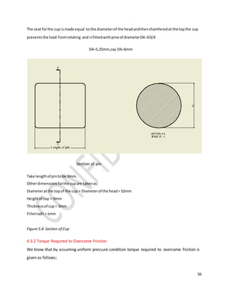
Where
𝜃 = the frictionangle.
Substituting(3.4) intoequation(3.3),
𝑃=(tan𝜃+tan𝛼)/(1−tan𝜃tan𝛼) (3.5)
𝑃=𝑊tan(𝛼+𝜃) (3.6)
The torque 𝑇 requiredtoraise the loadis givenby: 𝑇=𝑃×𝑑𝑚/2
Whence
𝑇=[𝑊tan(𝛼+𝜃)]𝑑𝑚/2 (3.7)
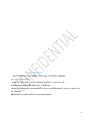
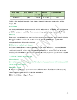
3.5 Torque Requirement - LoweringLoad
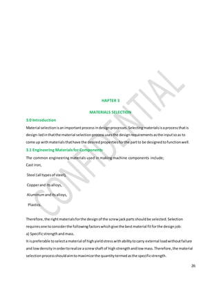
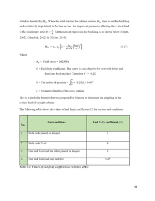
Whenthe loadis beinglowered,the followingforcesactat a pointonthe inclinedplane:
Load 𝑾: It alwaysactsin the vertical downwarddirection.
Normal reaction 𝑵: It acts perpendicular(normal) tothe inclinedplane.
Frictional force 𝝁𝑵:Frictional force actsopposite tothe motion.Since the loadismovingdownthe
inclinedplane,frictional force actsalong the inclinedplane inthe upwarddirection
Figure 3.7: Force diagramforlowering load
Effort 𝑷: The effort 𝑃 acts ina directionperpendiculartothe load 𝑊.It shouldact towardsleftto
overcome the frictionandlowerthe load.
Resolvinghorizontally,
𝑃 = 𝜇 𝑁 𝑐𝑜𝑠 𝛼 − 𝑁 𝑠𝑖𝑛 𝛼 (3.8)
Resolvingvertically,
𝑊 = 𝑁 𝑐𝑜𝑠 𝛼 + 𝜇 𝑁 𝑠𝑖𝑛 𝛼 (3.9)](https://image.slidesharecdn.com/screwjackproject-170620111154/85/Screw-jack-project-40-320.jpg)
![41
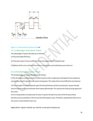
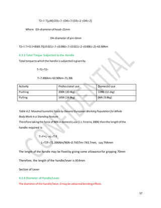
Dividingexpression(3.8) by(3.9) we get as follows:
𝑃=(𝜇cos𝛼−sin𝛼)/(cos𝛼+𝜇sin𝛼)
(3.10)
Dividingthe numeratoranddenominatorof the righthandside of equation(3.10) by cos α:
𝑃=(𝜇−tan𝛼)/(1+𝜇tan𝛼)
(3.11)
Substitutingequation(3.4) intoEquation(3.11),
𝑃=(tan𝜃−tan𝛼)/(1+tan𝜃tan𝛼)
(3.12)
Whence
𝑃 = 𝑊 𝑡𝑎𝑛 (𝜃 − 𝛼) (3.13)
The torque 𝑇 requiredtolowerthe loadisgivenby, 𝑇=𝑃×𝑑𝑚/2
Whence
𝑇=[𝑊tan(𝜃−𝛼)]𝑑𝑚/2
(3.14)
3.6 OverHaulingandSelf-LockingScrews
From equation(3.14),we knowtorque requiredtolowerloadisgivenby: 𝑇=[𝑊tan(𝜃−𝛼)]𝑑𝑚/218](https://image.slidesharecdn.com/screwjackproject-170620111154/85/Screw-jack-project-41-320.jpg)


![73
References
1. Ashby, M. F., 2005. Material Selection in Mechanical Design. 3rd ed. New York: Pergamon Press
.
2. Bhandari, V. B., 2010. Design of Machine Elements. Third Edition ed. New Delhi: Tata McGraw-
Hill Education.
3. Collection, J., 2015. hubpages.com› Autos › Automobile History. [Online] Available at:
https://www.history of screw jacks.com [Accessed 11 November 2015].
4. Fasteners, C. o., 2005. Technical Reference Guide. Ninth Edition ed. Winona, Minnesota: Fastenal
Industrial & Construction Supplies.
5. Gupta, R. K. &. J., 2005. Theory of Machines. Revised Edition ed. Punjab, India: S. Chand and
Company](https://image.slidesharecdn.com/screwjackproject-170620111154/85/Screw-jack-project-73-320.jpg)


![Final report[1]](https://cdn.slidesharecdn.com/ss_thumbnails/finalreport1-170515065010-thumbnail.jpg?width=640&height=640&fit=bounds)