
Recommended
More Related Content
What's hot
What's hot (20)
Viewers also liked
Similar to MULTI CAVITY DIE PREPARATION, ANALYSIS AND MANUFACTURING PROCESS OF DIESEL ENGINE PISTON
Similar to MULTI CAVITY DIE PREPARATION, ANALYSIS AND MANUFACTURING PROCESS OF DIESEL ENGINE PISTON (20)
More from Ijripublishers Ijri
More from Ijripublishers Ijri (20)
Recently uploaded
Recently uploaded (20)
MULTI CAVITY DIE PREPARATION, ANALYSIS AND MANUFACTURING PROCESS OF DIESEL ENGINE PISTON
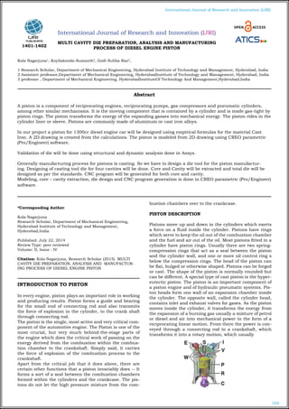
- 1. 164 International Journal of Research and Innovation (IJRI) International Journal of Research and Innovation (IJRI) MULTI CAVITY DIE PREPARATION, ANALYSIS AND MANUFACTURING PROCESS OF DIESEL ENGINE PISTON Kola Nagarjuna1 , Koyilakonda-Sumanth2 , Godi Subba Rao3 , 1 Research Scholar, Department of Mechanical Engineering, Hyderabad Institute of Technology and Management, Hyderabad, India 2 Assistant professor,Department of Mechanical Engineering, HyderabadInstitute of Technology and Management, Hyderabad, India 3 professor , Department of Mechanical Engineering, HyderabadInstituteOf Technology And Management,Hyderabad,India *Corresponding Author: Kola Nagarjuna Research Scholar, Department of Mechanical Engineering, Hyderabad Institute of Technology and Management, Hyderabad,India Published: July 22, 2014 Review Type: peer reviewed Volume: II, Issue : IV Citation: Kola Nagarjuna, Research Scholar (2015) MULTI CAVITY DIE PREPARATION, ANALYSIS AND MANUFACTUR- ING PROCESS OF DIESEL ENGINE PISTON INTRODUCTION TO PISTON In every engine, piston plays an important role in working and producing results. Piston forms a guide and bearing for the small end of connecting rod and also transmits the force of explosion in the cylinder, to the crank shaft through connecting rod. The piston is the single, most active and very critical com- ponent of the automotive engine. The Piston is one of the most crucial, but very much behind-the-stage parts of the engine which does the critical work of passing on the energy derived from the combustion within the combus- tion chamber to the crankshaft. Simply said, it carries the force of explosion of the combustion process to the crankshaft. Apart from the critical job that it does above, there are certain other functions that a piston invariably does -- It forms a sort of a seal between the combustion chambers formed within the cylinders and the crankcase. The pis- tons do not let the high pressure mixture from the com- bustion chambers over to the crankcase. PISTON DESCRIPTION Pistons move up and down in the cylinders which exerts a force on a fluid inside the cylinder. Pistons have rings which serve to keep the oil out of the combustion chamber and the fuel and air out of the oil. Most pistons fitted in a cylinder have piston rings. Usually there are two spring- compression rings that act as a seal between the piston and the cylinder wall, and one or more oil control ring s below the compression rings. The head of the piston can be flat, bulged or otherwise shaped. Pistons can be forged or cast. The shape of the piston is normally rounded but can be different. A special type of cast piston is the hyper- eutectic piston. The piston is an important component of a piston engine and of hydraulic pneumatic systems. Pis- ton heads form one wall of an expansion chamber inside the cylinder. The opposite wall, called the cylinder head, contains inlet and exhaust valves for gases. As the piston moves inside the cylinder, it transforms the energy from the expansion of a burning gas usually a mixture of petrol or diesel and air into mechanical power in the form of a reciprocating linear motion. From there the power is con- veyed through a connecting rod to a crankshaft, which transforms it into a rotary motion, which usually Abstract A piston is a component of reciprocating engines, reciprocating pumps, gas compressors and pneumatic cylinders, among other similar mechanisms. It is the moving component that is contained by a cylinder and is made gas-tight by piston rings. The piston transforms the energy of the expanding gasses into mechanical energy. The piston rides in the cylinder liner or sleeve. Pistons are commonly made of aluminum or cast iron alloys. In our project a piston for 1300cc diesel engine car will be designed using empirical formulas for the material Cast Iron. A 2D drawing is created from the calculations. The piston is modeled from 2D drawing using CREO parametric (Pro/Engineer) software. Validation of die will be done using structural and dynamic analysis done in Ansys. Generally manufacturing process for pistons is casting. So we have to design a die tool for the piston manufactur- ing. Designing of casting tool die for four cavities will be done. Core and Cavity will be extracted and total die will be designed as per the standards. CNC program will be generated for both core and cavity. Modeling, core – cavity extraction, die design and CNC program generation is done in CREO parametric (Pro/Engineer) software. 1401-1402
- 2. 165 International Journal of Research and Innovation (IJRI) Drives a gearbox through a clutch. Components of a typi- cal, four stroke cycle, DOHC piston engine. (E) Exhaust camshaft, (I) Intake camshaft, (S) Spark plug, (V) Valves, (P) Piston, (R) Connecting rod, (C) Crankshaft, (W) Water jacket for coolant flow. Suzuki GS 150 R specifications Engine type : air cooled 4-stroke SOHC Bore ×stroke(mm)=57×58.6 Displacement =149.5CC Maximum power = 13.8bhp @8500rpm Maximum torque = 13.4Nm @ 6000 rpm Compression ratio =9.35/1 3D MODEL PREPARATION SKETCHER REVELOVED MODEL SLOT CUTTING INTRODUCTION TO CASTING Casting is one of the oldest procedures done on metals. Many products are formed using this method. Here is an attempt to share the knowledge of casting. Casting is one of four types: sand casting, permanent mold casting, plaster casting and Die casting. All these types of castings have their own advantages and disad- vantages. Depending on the properties of the product re- quited, one of the casting is selected. Sand Casting: Sand casting is the oldest casting of the above. This method of casting is in use since 1950.The texture of the product depends on the sand used for cast- ing. The end product is given smooth finishing at the end. Usually iron, steel, bronze, brass, aluminium, magnesi- um alloys which often include lead, tin, and zinc are used. DIE CASTING Die casting is a metal casting process that is character- ized by forcing molten metal under high pressure into a mold cavity, which is machined into two hardened tool steel dies. Most die castings are made from non-ferrous metals, specifically zinc, copper, aluminium, magnesium, lead, pewter and tin based alloys. Depending on the type of metal being cast, a hot- or cold-chamber machine is used. Volume of the component ;(v) =83406.96 Projected area ;(a)=3569.66 A1 (side wall) =1275.88 Density of material ;26e-6+ Mass No Of Cavities x=4 Total projected area =a*x =3569.66*4 A=14278.64 Projected area of over flows and feed system Af=A *c/100 C=10% of A =142.78 Over all projected area:- =A+a1+Af =14278.64+142.78+1275.88 =15697.3mm2 Specific injection pressure of aluminum for pressure DIA casting =8kgf/mm2 Total force acting on die plates F=projected area *injection pressure =15697.3*8 =125578.4kg =125.57 Tons Considering factor of safety of *1.2 125.5784*1.2=150.69=151 Tons Required clamping force >150 tons 160 tons machine specifications Clamping force =160 tons Die stroke =380mm Die - height =200-550mm Plate size =675*680 Injection stroke (L)=340 Plunger die =50,60,65mm Shot wt =1.3,1.8,2.1 FILL TIME :- 0.092(582-516+(0.3*4.8))8.93/(516-100) =0.092(66+(1.44))8.923/416 =0.092*67.44*8.93/416 =55.40/416 =0.133sec =133 kg sec MANUFACTURING (MOLD EXTRACTION) A die is usually made in two halves and when closed it forms a cavity similar to the casting desired. One half of the die that remains stationary is known as cover die and the other movable half is called “ejector die”.
- 3. 166 International Journal of Research and Innovation (IJRI) Molds separate into at least two halves (called the core and the cavity) to permit the part to be extracted. In gen- eral the shape of a part must not cause it to be locked into the mold. For example, sides of objects typically cannot be parallel with the direction of draw (the direction in which the core and cavity separate from each other). They are angled slightly (draft), and examination of most plastic household objects will reveal this. Parts that are "bucket- like" tend to shrink onto the core while cooling, and after the cavity is pulled away. Pins are the most popular meth- od of removal from the core, but air ejection, and strip- per plates can also be used depending on the application. Most ejection plates are found on the moving half of the tool, but they can be placed on the fixed half. Core: The core which is the male portion of the mold forms the internal shape of the molding. Cavity: The cavity which is the female portion of the mold, gives the molding its external form. Shrinkage allowance considered as 1.3% for aluminum and the mould draft considered as 1°. CORE & CAVITY PREPARATION OF MODEL PARTING SURFACE CAVITY CORE CASTING TOOL DESIGN FOR MULTY CAVITY PISTON EXPLODED VIEW STRUCTURAL ANALYSIS ON MULTI CAVITY PISTON DIE The above image shows imported model The above image shows meshed model
- 4. 167 International Journal of Research and Innovation (IJRI) The above image shows load applied The above image shows total deformation The above image shows stress INTRODUCTION TO MANUFACTURING The manufacturing of various products is done at differ- ent scales ranging from humble domestic production of say candlesticks to the manufacturing of huge machines including ships, aeroplanes and so forth. The word manu- facturing technology is mainly used for the latter range of the spectrum of manufacturing, and refers to the com- mercial industrial production of goods for sale and con- sumption with the help of gadgets and advanced machine tools. Industrial production lines involve changing the shape, form and/or composition of the initial products known as raw materials into products fit for final use known as finished products. PROCEDURE OF MANUFACTURING CAVITY ROUGHING CUTTING TOOL VERICUT ROUGHING PROGRAM % G71 O0001 (D:nsrroughing.ncl.1) N0010T1M06 S5000M03 G00X5.Y-5. G43Z0.H01 G01Z-5.F200. X201.177 Y-9.914 X5. Y-14.828 X201.177
- 5. 168 International Journal of Research and Innovation (IJRI) Y-19.742 X5. Y-24.656 X201.177 Y-29.57 X5. Y-34.484 X201.177 Y-39.398 X5. Y-44.313 Results table STRUCTURAL ANALYSIS Existing Model Modified Model Total deformation 0.010822 0.0090683 Stress 37.317 31.116 Strain 0.00034214 0.00028758 FATIGUE ANALYSIS Existing Model Modified Model LIFE 1e6 1e6 Damage 1000 1000 Safety factor 2.3099 2.7703 Biaxiality indica- tion 0.98181 0.99333 Alternating stress 37.317 31.116 graphs Conclusion: This project work deals with “Multy cavity die preparation and manufacturing process of diesel engine piston". In the first step data collection and inputs are collected for the design of piston for diesel engine. In the next step design calculations are done using math- ematical formulae’s from the calculations piston dimen- sions are required. A 3d model was generated using above calculations. Tool design calculations are done to prepare the die as- sembly. Core and cavity inserts are prepared using manufactur- ing model in pro- engineer. Mould tool parts are prepared and assembled withdrew set. Structural and Fatigue Analysis is conducted on mold to find structural and Fatigue behavior to, modification’s done for core & cavity models to increase strength by add- ing stress relief holes. CNC program was generated for both core and cavity in- serts.
- 6. 169 International Journal of Research and Innovation (IJRI) By observing above information it concludes that using above process piston manufacturing can be done with multy cavities so it increases the production rate which in terms effect’s on reduction of cost of part production. REFERENCES 1.Thermal analysis and optimization of i.C. Engine piston using finite element method 2.Design and analysis of i.C. Engine piston and piston- ring using catia and ansys software 3.Design analysis and optimization of piston using catia and ansys 4.Simulation of thermal-mechanical strength for marine engine piston using fea 5.Thermal analysis and optimization of i.C. Engine piston using finite element method 6.Modeling and analysis of diesel engine piston 7.Modeling, analysis and optimization of diesel engine piston 8.Thermal analysis of diesel engine piston 9.Finite element analysis and optimization of i.C. Engine piston using radioss and optistruct author Kola Nagarjuna Research Scholar, Department of Mechanical Engineering, Hyderabad Institute of Technology and Management, Hyderabad,India Koyilakonda-Sumanth Assistant professor Department of Mechanical Engineering, Hyderabad Institute of Technology and Management, Hyderabad,India Godi Subba Rao professor Department of Mechanical Engineering, Hyderabad Institute of Technology and Management, Hyderabad,India