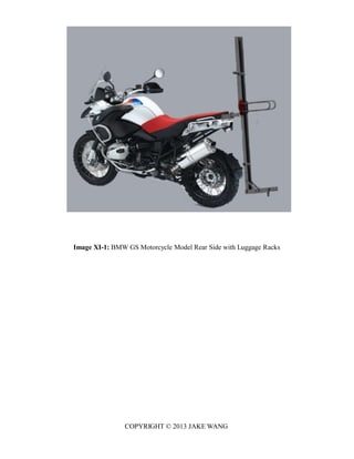
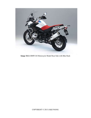
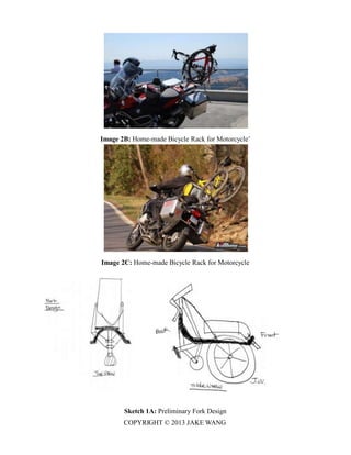
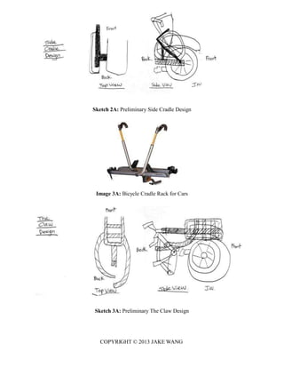
This document presents the design of a bike rack for motorcycles. It includes analyses of the strength, deflection, buckling, and fatigue of the design. The bike rack consists of six parts that are connected to the luggage rack of a BMW GS motorcycle. Analyses were performed on the vertical beam mainframe to verify the design meets requirements for a maximum load of 240 pounds, deflection less than 1 inch, and a lifetime of 10,000 trips. Material properties and dimensions are presented and the analyses show the design is strong enough while being inexpensive and lightweight.


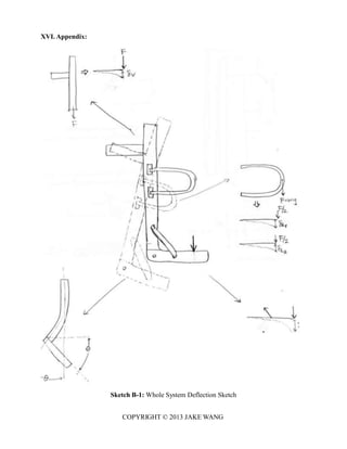
![COPYRIGHT © 2013 JAKE WANG
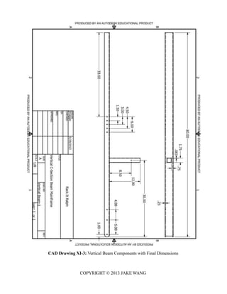
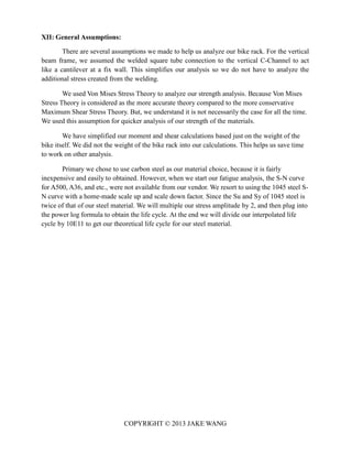
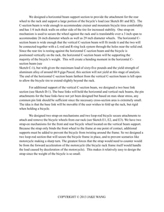
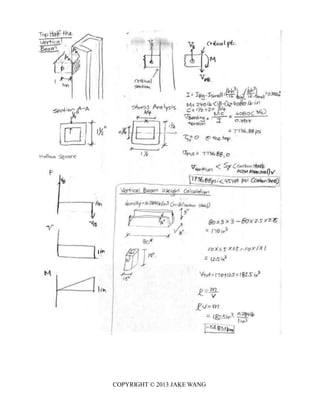
Table XI-1: Vertical Beam Mainframe Final Dimensions/Weight/Cost
Vertical Beam: Design Parameters
Material: A36
Sets H
[inches]
W
[inches]
L
[inches]
t [inches]
3 3 1 1/2 80 1/4
Welded Square Tube: Design Parameters
Material: A513
Sets H
[inches]
W
[inches]
L
[inches]
t [inches]
3 1 1/2 1 1/2 10 3/4
Subtotal Weight [lbs.] 49.25
Subtotal Cost [$] 118.88
Subtotal Deflections
[in]
0.018472](https://image.slidesharecdn.com/jakewangbikerackdesignproject-140430134306-phpapp01/85/Bike-Rack-Design-Project-10-320.jpg)
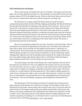
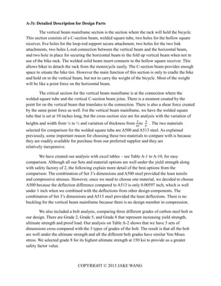
![3)Table A1-2: Material Properties for Design Parts
Table A-1: Material Properties for our Steel Square Tubing
Table A-2: Material Properties for our Bolt Options
Table A-3:SAE1045 Steel Fatigue S-N Curve
COPYRIGHT © 2013 JAKE WANG
Major Design Component
Steel Tubing
Material/Grade ASTM A500
Steel*
ASTM A513 Steel*
Density (p) 0.284
[lbf/in^3]
Elastic Modulus
(E)
20300 [kpsi] 30000 [kpsi]*
Poisson's ratio (v) 0.292
Yield Strength
(Sy)
45700 [psi] 72000 [psi]
Ultimate Strength
(Su)
58000 [psi] 87000 [psi]
* Assume 30000. No data
found.
Bolt Component
Material/Grade Low Carbon Bolt
**
Grade 2 5 8
Yield Strength (Sy) 57000 [psi] 92000 [psi] 130000
[psi]
Ultimate Strength
(Su)
74000 [psi] 120000[psi] 150000[psi]
Proof Load 55000 [psi] 85000 [psi] 120000[psi]
(low carbon steel)](https://image.slidesharecdn.com/jakewangbikerackdesignproject-140430134306-phpapp01/85/Bike-Rack-Design-Project-22-320.jpg)
![COPYRIGHT © 2013 JAKE WANG
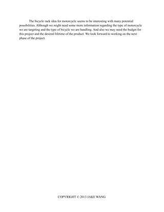
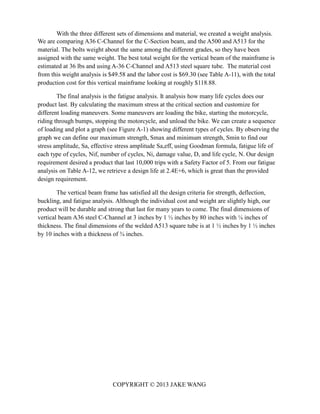
A.5) Detailed Analysis Comparison
i) Table A-: Strength Analysis
Table A-3: Complete Table of Available Dimensions Welded Square Tube Analysis
Welded Square Tube: Design Parameters
Dimensions
Sets H [inches] W [inches] L [inches] t [inches]
1 1 1/4 1 1/4 10 3/16
2 1 1/2 1 1/2 10 1/4
3 1 1/2 1 1/2 10 3/4
Parts Design Parameters
Area Calculations
Sets A [inches^2]
1 2/3
2 1 1/4
3 2 1/4
Parts Design Parameters
Moment of Inertia Calculations
Sets I [inches^4]
1 1/6
2 1/3
3 3/7
Parts Design Parameters
Distance from the edge to Bolt
(e)
Sets e [inches]
1 1
1 1 1/2
1 2
2 1
2 1 1/2
2 2
3 1
3 1 1/2
3 2](https://image.slidesharecdn.com/jakewangbikerackdesignproject-140430134306-phpapp01/85/Bike-Rack-Design-Project-27-320.jpg)
![COPYRIGHT © 2013 JAKE WANG
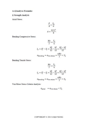
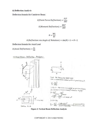
ii) Table A-: Deflection Analysis
Parts Material
Strength Set A500 Von
Mises
<Sy A513 Von
Mises
<Sy Best Set
Ranking
Tensile Stress [psi] 1 16493 14400 Yes 3709 3138 Yes 3
24/25 1/11 6/13
2 9038 7253 Yes 2448 1360 Yes 2
10/13 1/3
3 7253 7253 Yes 1360 1360 Yes 1
1/3 1/3
Compressive Stress 1 -16493 - Yes -3138 -3138 Yes 3
[psi] 24/25 14400 6/13 6/13
(Note: A500: 2 -9038 -7253 Yes -1360 -1360 Yes 2
Sy=45700 [psi]) 10/13 1/3
(Note: A513: 3 -7253 -7253 Yes -1360 -1360 Yes 1
Sy=72000 [psi]) 1/3 1/3
Best Material
Ranking
1 2
Parts Material
Deflections Set A500 A513
Vertical Deflection [in.] 1 19/400 9/280
(Note: E=20300 [kpsi]) 1 21/131 32/295
1 19/50 9/35
2 19/800 9/560
2 21/262 16/295
2 19/100 9/70
3 15/812 1/80
3 25/401 17/403
3 103/697 1/10
Deflections for design part
[in.]
1 19/400 9/280
2 19/800 9/560
3 15/812 1/80 Deflection
Difference
Min Deflections for design
part [in.]
Set
3
15/812 1/80 2/335](https://image.slidesharecdn.com/jakewangbikerackdesignproject-140430134306-phpapp01/85/Bike-Rack-Design-Project-28-320.jpg)
![COPYRIGHT © 2013 JAKE WANG
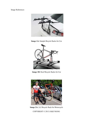
iii) Table A-Buckling Analysis
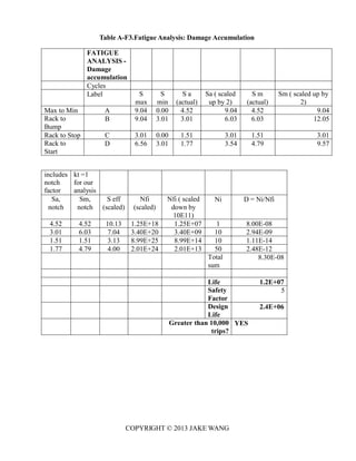
iv) Table A-Fatigue Analysis
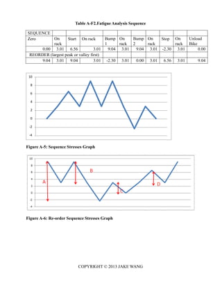
Table A-F1.Fatigue Analysis
Parts Material
Buckling Set A500 <Sy [Yes/No] A513 <Sy [Yes/No]
Tensile Stress [psi] 1 0 0 0 0
2 0 0 0 0
3 0 0 0 0
Compressive Stress [psi] 1 0 0 0 0
2 0 0 0 0
3 0 0 0 0
(Comments: Due to no compressive force acting on the vertical beam, the beam would not
buckle.)
Vertical Beam Welded Tube Fatigue Analysis:
GEOMETRY MATERIAL A1045 Steel
D 0.85 inch Sy 105 ksi
Su 84 ksi
I 0.3385 inch^4 A 152 ksi, (for fully
reversed loading)
A N/A inch^2 b -0.065
c 0.7500 inch
Kt, notch 1.0000 (unnotched)
LOADING
Maneuver Fx [lbs] Fy [lbs] P [lbs] V [lbs] M
[lb*in]
Stress @ Welded Tube
(Mc/I) [ksi]
Load Bike 0 0 0 0 0 0.00
On rack 0 80 0 80 1360 3.01
Start 40 80 40 80 2960 6.56
Bump 0 240 0 240 4080 9.04
Stop -60 80 -60 80 -1040 -2.30
On rack 0 80 0 80 1360 3.01
Unload
Bike
0 0 0 0 0 0](https://image.slidesharecdn.com/jakewangbikerackdesignproject-140430134306-phpapp01/85/Bike-Rack-Design-Project-29-320.jpg)
![COPYRIGHT © 2013 JAKE WANG
Table A-W1.Vertical Beam and Welded Tube Weight Analysis
Table A-C1.Vertical Beam and Welded Tube Cost Analysis
Components Weight
Sets Vertical Beam [lb] Welded Tube [lb] Bolts
[lb]
Total Weight [lb] Selection
Ranking
1 34 2 1/4 36 18/61 1
2 45 1/2 3 5/9 1/4 49 9/35 2
3 42 3/5 6 2/5 1/4 49 9/35 2
Vertical Beam and Welded Tube Cost
Analysis
Material: C
Channel
A-36
Steel
Welded
Tube
A500
Steel
Components Costs
Sets Vertical
Beam [$]
Welded
Tube [$]
Bolts
[$]
Material
Cost [$]
Labor
Cost
[$]
Total
Cost
[$]
Selection
Ranking
1 40.96 21.66 2 64.62 69.30 133.92 1
2 52.00 13.32 2 67.32 69.53 136.85 2
3 51.84 18.00 2 71.84 69.91 141.75 3
Vertical Beam and Welded Tube Cost
Analysis
Material: C
Channel
A-36
Steel
Welded
Tube
A513
Steel
Components Costs
Sets Vertical
Beam [$]
Welded
Tube [$]
Bolts
[$]
Material
Cost [$]
Labor
Cost
[$]
Total
Cost
[$]
Selection
Ranking
1 40.96 6.62 2 49.58 69.30 118.88 1
2 52.00 6.24 2 60.24 69.53 129.77 2
3 51.84 7.82 2 61.66 69.91 131.57 3](https://image.slidesharecdn.com/jakewangbikerackdesignproject-140430134306-phpapp01/85/Bike-Rack-Design-Project-32-320.jpg)
![COPYRIGHT © 2013 JAKE WANG
Table A-L: Vertical Beam and Welded Tube Labor Cost Analysis
Vertical Beam and Welded Tube Labor Cost Analysis
Material: C
Channel
A-36
Steel
Welded
Tube
A500 or
513 Steel
Sets 1 2 3
Processes Unit Cost
[$]
# of Units
or Length
[cm]
Subtotal
Cost [$]
Unit
Cost
[$]
# of Units
or Length
[cm]
Subtotal
Cost [$]
Unit
Cost
[$]
# of Units
or Length
[cm]
Subtotal
Cost [$]
Vertical
Tube
Drilled $ 5 $ $ 5 $ $ 5 $
holes <
25.4 mm
dia. 0.35 1.75 0.35 1.75 0.35 1.75
Saw or $ 40.54 $ $ 40.54 $ $ 40.54 $
tubing cuts 0.40 16.22 0.40 16.22 0.40 16.22
Welded
Tube
Tube end $ 1 $ $ 1 $ $ 1 $
preparation
for
welding 0.75 0.75 0.75 0.75 0.75 0.75
Weld $ 1.69 $ $ 3.18 $ $ 5.72 $
0.15 0.25 0.15 0.48 0.15 0.86
Tube cut $ 35.56 $ $ 35.56 $ $ 35.56 $
0.15 5.33 0.15 5.33 0.15 5.33
Assembly
Assemble, $ 12 $ $ 12 $ $ 12 $
>20 kg,
Line-on-
Line 3.75 45.00 3.75 45.00 3.75 45.00
Total $ Total $ Total $
Labor Labor Labor
Cost 69.30 Cost 69.53 Cost 69.91
Ranking (Least to
Highest Price)
1 2 3](https://image.slidesharecdn.com/jakewangbikerackdesignproject-140430134306-phpapp01/85/Bike-Rack-Design-Project-33-320.jpg)