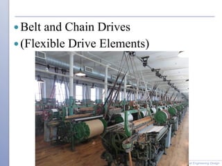
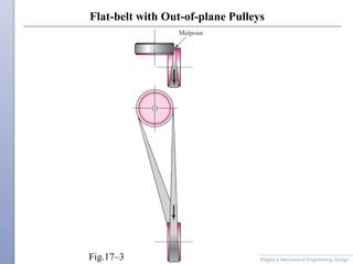
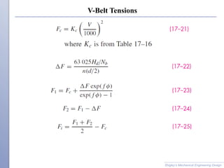
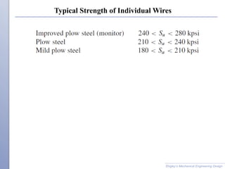
The document discusses various types of flexible drives used to transmit power between shafts, including belts, chains, ropes, and flexible shafts. It provides details on belt and chain types, characteristics, design considerations, equations, and examples. Flexible drives allow for power transmission over long distances between shafts compared to rigid couplings and can accommodate some misalignment, though they have speed and power limits compared to gears.
2. Why Flexible Drives?
Shigley’s Mechanical Engineering Design
+
• Long Distances Between Shafts
• Less Expensive
• Adjustable Centers
• Tolerates some mis alignment better than gears
-
• Not as compact as gears
• Some speed limits
• Power and torque limits
3. Common Belt Types
Shigley’s Mechanical Engineering Design
Type Pulley
1. Flat Crowned pulley
(conveyor belts)
2. Round (O-ring) Grooved pulley
3. V-belt Flanged pulleys
4. Timing (toothed) Cogged pulley
(no stretch or slip)
5. Proprietary belt designs
5. Flat Belt Drive
Shigley’s Mechanical Engineering Design
Better for high speed applications,
rather than power.
Good for tight clearances
Can allow slip, to prevent breakage
6. Flat Belts as Conveyer Belts
Shigley’s Mechanical Engineering Design
Usually seamed/stitched
Crowned Pulleys for Tracking
37. Belting Selection
Shigley’s Mechanical Engineering Design
Use Belting Manufacture Specific Data
For examples Gates Belts (know mostly for V-belts)
https://www.gates.com/us/en.html
Available Resources from the Manufacturer
• Products and Applications (by Industry)
• Engineering Applications & Design Software
• Calculators
• Resources Library
39. Roller Chain Characteristics
Shigley’s Mechanical Engineering Design
• Similar to Timing Belts, no slip
• Long life
• Fairly large power can be transmitted
• Costs less than gears
• Easy to adjust centers, tolerant of large variation
• Input and Output sprocket usually rotate in same direction
• Only need light to no chain preload tension
when installing, but may require a tensioner/idler
• Usually requires lubrication
• Can use multiple strands for increased power
• Usually made of steel
• Stainless steel versions available for food industry
41. ANSI Chain Size Number
Shigley’s Mechanical Engineering Design
XXX
First number(s) pitch p in number of 1/8”
ANSI 40 chain is 4 x1/8” =0.50” pitch
0=Standard
1=Light Duty
ANSI 41 chain is 4 x1/8” =0.50” pitch
But Light Duty
42. Dimensions of American Standard Roller Chains
Shigley’s Mechanical Engineering Design
Table 17–19
43. Engagement of Chain and Sprocket
Shigley’s Mechanical Engineering Design
Fig.17–17
45. Roller Chain Design Guide Rules of Thumb
Shigley’s Mechanical Engineering Design
• Min Teeth per Sprocket ~ 12 to 25
• Max Teeth per Sprocket ~120
• Max Speed Reduction ~7:1
• Min Wrap Angle ~ 120˚
58. Equivalent Bending Load in a Pulley, diameter D
Wire rope tension giving same tensile stress as sheave bending is
called equivalent bending load Fb
Clearly the smaller the sheave diameter the higher the added
bending tension of the sheave on the cable
Shigley’s Mechanical Engineering Design
59. Percent Strength Loss for D/d
Shigley’s Mechanical Engineering Design
Fig.17–20
D is sheave (pulley) diameter
d is the cable diameter
60. Minimum Factors of Safety for Wire Rope
Shigley’s Mechanical Engineering Design
Table 17–25
61. Bearing Pressure of Wire Rope in Sheave Groove
Shigley’s Mechanical Engineering Design
63. Relation Between Fatigue Life of Wire Rope and Sheave Pressure
Shigley’s Mechanical Engineering Design
Fig.17–21
64. Fatigue of Wire Rope
Fig. 17–21does not preclude failure by fatigue or wear
It does show long life if p/Su is less than 0.001.
Substituting this ratio in Eq. (17–42),
Dividing both sides of Eq. (17–42) by Su and solving for F, gives
allowable fatigue tension,
Factor of safety for fatigue is
Shigley’s Mechanical Engineering Design
65. Factor of Safety for Static Loading
The factor of safety for static loading is
Shigley’s Mechanical Engineering Design
66. Typical Strength of Individual Wires
Shigley’s Mechanical Engineering Design
67. Service-Life Curve Based on Bending and Tensile Stresses
Shigley’s Mechanical Engineering Design
Fig.17–22