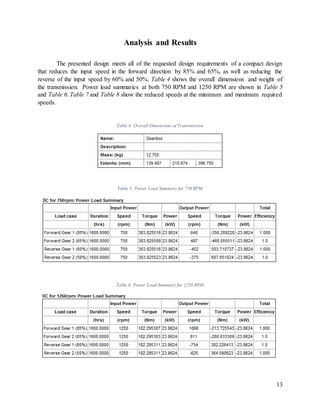
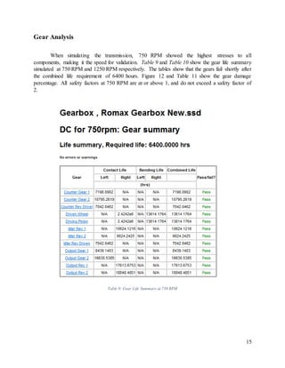
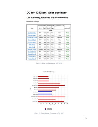
The project presents a two speed transmission. Design requirements for the transmission state that it must have two forward gears and two reverse gears, be compact, be quiet, and have a collinear design. Also, the design must last for 1600 hours at each gear for a combined life of 6400 hours between 750 and 1250 rotations per minute (RPM) with a power input of 32 horsepower. The output shaft must rotate at 85% (±1%) and 65% (±1%) of the input speed in the input direction, and 60% (±1%) and 50% (±1%) of the input speed in the opposing direction. The design chosen consists of an input shaft, counter shaft, idler shaft, and an output shaft assemblies which were all designed using helical gears, tapered roller bearings, and radial ball bearings. Validation of the gears, bearings, and shafts were done using RomaxDesigner software. Analysis of the duty cycle summary for the final design shows design failure shortly after the required combined life of 6400 hours.
1. 1
Western Michigan University
College of Engineering and Applied Sciences
Department of Mechanical & Aerospace Engineering
ROMAX TRANSMISSION DESIGN
Authors: Rafael Ayala & Robert Beneteau
ME 3650 Machine Design I
Dr. Judah Ari-Gur
April 20, 2018
2. 2
Abstract
The project presents a two speed transmission. Design requirements for the transmission
state that it must have two forward gears and two reverse gears, be compact, be quiet, and have a
collinear design. Also, the design must last for 1600 hours at each gear for a combined life of 6400
hours between 750 and 1250 rotations per minute (RPM) with a power input of 32 horsepower.
The output shaft must rotate at 85% (±1%) and 65% (±1%) of the input speed in the input direction,
and 60% (±1%) and 50% (±1%) of the input speed in the opposing direction. The design chosen
consists of an input shaft, counter shaft, idler shaft, and an output shaft assemblies which were all
designed using helical gears, tapered roller bearings, and radial ball bearings. Validation of the
gears, bearings, and shafts were done using RomaxDesigner software. Analysis of the duty cycle
summary for the final design shows design failure shortly after the required combined life of 6400
hours.
4. 4
Introduction
The transmission was designed to have two different output gear speeds as well as two
different reverse output speeds. The first gear was to be at 85% of the input speed, 65% for the
second gear, while the two reverse gears were required to be 60% and 50% of the input speed in
the opposite direction of the input shaft. All components used in the transmission system were
required to withstand the loads of the 32 horsepower input ranging from 750 to 1250 RPM. All
gears in the system were required to last a minimum of 1600 hours of operation for each of the
four output speeds. When different gears are selected, the power of the transmission changes
depending on which synchronizer is selected for the specific gear set. For this, the bearings and
gears were optimized to reduce over-engineering of the design to make the gears fail as close to
the required combined life of 6400 without failing before that mark. The final design of the gear
box contains four shafts; input shaft, counter shaft, idler shaft, and output shaft with six sets of
gears; primary gears, forward 85% gears, forward 65% gears, idler gears, reverse 60% gears, and
reverse 50% gears.
Design
Design Overview
The design process was a meticulous one, which began by deciding what main gear ratios
would be used to acquire the desired speed output percentages while still trying to keep the overall
design compact. A major factor of this was the center distance of the shafts as this would not only
determine the height of the transmission, but also the width of it as well. To help minimize the size
of the transmission, the center distance between the input shaft and the counter shaft were set to
100 mm. The center distance that was chosen was found to be a reasonable size as well easy to
make calculations between centers for characteristics such as gear sizing. Other key design features
were using a 20 degree helix angle on all gear sets, different materials, and ISO gear quality
standards to modify gear life.
Layout
The layout for the transmission was based off that of a manual transmission that would be
found in most vehicles today with the exception of the reverse gears, where helical gears are
mounted on a fixed idler shaft using synchronizers to engage instead of horizontally moving spur
gear. The general design of the gearbox that was used as reference is shown below in Figure 1.
Using this layout and a set center distance between the input shaft and the counter shaft of 100
mm, the gears were able to be optimally designed for the input, output, and counter shafts. The
requirements for the transmission were that gear life at each output percentage withstand 1600
5. 5
hours of operation for a combined total of 6400 hours. The transmission would then be tested at
both extremes of the required operations speeds of 750 RPM and 1250 RPM. The slower rotational
speed transmitted more torque through the gears than that of the higher speed, thus making 750
RPM the optimal test fatigue and failure in the gears, bearings, and shafts. The designation of the
newly designed transmission can be seen in Figure 2.
Figure 1: General Manual Transmission
6. 6
Figure 2: Design Layout and Designation
Gear Design
The primary function of gears is to transmit rotational motion which is done by the
interlocking of teeth. As one gear rotates, the other gear that is meshed with it will rotate with the
same tangential velocity in the opposite direction of rotation. Within a transmission, gears have a
secondary function which is to change the rotational velocity between shafts. This can be
accomplished by meshing a larger diameter gear with a smaller diameter gear. The gear providing
the rotational motion to the gear set is called the “pinion” where the gear being rotated is known
as the “Wheel”. Figure 3 below shows a basic schematic of a meshing gear set.
There are many different types of gears based around the style of teeth of the gear. One of
the most common types of gear teeth is a spur gear shown in Figure 4. For this design however,
spur gears have a disadvantage of being noisy when meshing. Due to the design requirements, the
noise of the gears must be minimized as much as possible. Unlike spur gears, helical gears are
designed with teeth at an angle, allowing for greater gear loads as well as quieter operation seen
in Figure 5. The angled teeth of the helical gear however, create axial forces that are translated to
the shaft making the gears more difficult to mesh. Due to these axial forces, there are rules to
meshing two helical gears together such as; opposing tooth angles, number of teeth to avoid
undercutting, and the gear modules must be the same between the two. Opposing gear tooth angle
can also be seen in Figure 5.
Input Shaft
PrimaryPinion
85% Forward
Wheel
65% Forward
Wheel
60% Reverse
Wheel
50% Reverse
Wheel
Output Shaft
Idler Shaft
50% Reverse
Pinion
Counter Shaft
PrimaryWheel 85% Forward Pinion
65% ForwardPinion
Idler Pinion
60% Reverse
Pinion
Pinion Wheel
7. 7
Undercutting is an occurrence when there is interference between gear teeth. As a result of
the interference, there is excessive wear to the base of the gear teeth causing life of operation to
decrease drastically. Undercutting can be avoided by designing gears to have more teeth to reduce
the amount of force applied to a single tooth. An example of undercutting is shown in Figure 6.
Figure 3: Basic Gear Set Figure 4: Example Spur Gear
Figure 5: Helical Gear Set W/ Opposing Teeth
Figure 6: Example of Undercutting
8. 8
Gear reduction was an important factor in finding the correct parameters for the gear set
using the module number. The module number is a ratio based around the reference diameter of
the gear divided by the number of teeth. Most modules use a standardization of numbers between
1 and 3 at increments of 0.5. Once finding the reference diameter of the gears, the reduction ratio
is a division of the smaller diameter gear by the product of the larger diameter gear and the primary
gear ratio. This gear reduction ratio is the actual speed reduction for that gear set. This was best
solved using a spreadsheet for quick and precise calculations.
After the gear reduction was satisfied, the total gear life could be analyzed. The total life
of the gears was reliant on the gear material, face width, and decreasing the web width. Out of the
listed gear life properties, changes in the material were made first. For the primary and forward
gears, nitrided 4140 steel was used, where case hardened steel was used for the idler pinion and
wheel set, leaving the reverse gear sets to be made from nitrided, through hardened steel. Nitriding
is a heat treating process that diffuses nitrogen into the surface of the material to create a case-
hardened surface which will increase the gear tooth’s hardness. Case hardened steel has a similar
effect as nitriding but caused by carbonizing the outer surface but the outcome is much more
profound. Figure 7 below shows a cross-section of a case hardened gear. Through hardened steel
has similar effects as case hardened steel, but the carbonizing takes place throughout the entirety
of the material. Though hardened steel is usually a medium or high carbon steel.
Figure 7: Cross-Section of Case Hardened Gear
Due to shaft bending, changes in the gear face width were minimized as much as possible
without sacrificing the required gear contact or bending life. Having shaft bending causes the gear
set to mesh at angles relative to the horizontal, causing improper meshing parameters and reducing
gear life. As the face width of the gears increases, this effect becomes exaggerated. The gear
materials and dimension selections are shown below in Table 1.
9. 9
Table 1: Selected Gear Details
In order to the output shaft to spin in the reverse direction, an idler needed to between the
gear on the counter shaft and the gear on the output shaft. In most instances this can create a set of
three gears. For this design instance, a set of secondary gears will drive the idler shaft where then
two separate sets of gears will then be used for the gear reduction as seen below in Figure 8.
Figure 8: Idler Gear Meshings Using Secondary Gear Set
The gears were designed to fail shortly after the 6400 hour operation period. To design for
an infinite operation life would be impractical and very expensive. Given that the customer wanted
an operation life of 6400 hours, it was decided that the gears would fail first as it would not result
in any catastrophic failure or damage to any other components, only a loss of transmitted power.
10. 10
Bearing Design
The main purpose of a bearing is to allow rotation of an object while constraining that
objects physical position in space. In this design, bearings are placed at both ends while the counter
and output shafts have a bearing placed near the middle of the shaft. Due to the helical gears that
were chosen in this design creating an axial force along the shaft, the bearings that we chose had
to support the shafts rotation and the axial force. To counter the axial force being applied along
the shafts, taper bearings were used to continue to meet the requirements. Taper bearings were
chosen because of the conical shape of the tapered roller bearings. Figure 9 below shows the cut-
away of a taper bearing.
Even though taper bearings became the bearing of choice to be mounted at each end of all
the shafts, the axial forces on the shafts were not the same in both directions, therefore, in some
places such as the idler shaft, different sized taper bearings were able to be used to support the
shaft. Similar to the design of the gears, the bearings were designed to fail not long after the
required total hours of operation. Using a smaller bearing would reduce the amount of rotating
mass and thus improve efficiency with a sacrifice to operational hours. Bearings with a steeper
contact angle withstood more radial forces but tended to have a much larger outer diameter than a
bearing with a shallower contact angle. Even though the bearings were designed to fail shortly
after the required hours of operation, the design has the bearings lasting longer that the life of the
gears to help prevent catastrophic failure and damaging other components within the transmission
as well as providing more safety for the end user. Table 2 shows the bearing selection and details
for each shaft.
Figure 9: Taper Bearing Section View
11. 11
Table 2: Bearing Selection and Properties
Shaft Design
Shafts are used to constrain the location of the gears to one another, as well as transfer
rotational motion between two gears. The shafts must be able to hold up to the rotational and axial
forces that cause shear and bending stresses. Figure 10 below shows a sample shaft from a
transmission.
Figure 10: Sample Shaft of a Transmission
Material and shaft diameter were optimized to meet the total required design life. Material
selections is important property to consider. Choosing a material that is too hard and brittle will
cause the shaft to break under the high impact loads of having to change gears. However, a material
that is too soft and malleable will be prone to the twisting and axial forces from the gears. For this
design of the transmission, nitrided mild steel was chosen as the material for all four of the shafts.
The shaft design data is shown below in Table 3.
Table 3: Shaft Details
12. 12
While creating the placements for all of the bearings and gears for all of the shafts, the shifting
mechanisms had to be taken into account. The shaft needed to be long enough to hold all of the
needed gears, synchronizers, and spline gears yet small enough to keep the specification of a
compact design. Even though synchronizers were not to be included in the design the space for
implementing them into the design still had to be included. This cause the placement of the gears
and the diameter of the shaft to be crucial. Specific component placement can be seen in Appendix
A.
Shifting Mechanism
Manual transmissions change gears by locking and unlocking the drive gears to the output
shaft through the use of synchronizers. The output gears ride on bearings on the output shaft and
are only driving the shaft when the collar from the shifting mechanism meshes that gear’s
synchronizer with the dog gear which is connected to the shaft. The shifting collar engages and
disengages from the gear’s synchronizers by actuating from mechanical linkages. When the
shifting collar is actuated and engaged to the gear’s synchronizer, the gear will essentially be
locked into the output speed of the shaft. To reduce the number of shifting components within the
design, the synchronizers and collars were placed between the two forward gears and another
placed between the two reverse gears. Figure 11 below shows the designation of the shifting
components in the designed transmission.
Figure 11: Example Designation of Shifting Components
Synchronizers and collar for
shifting mechanism between
85% forward gear and 65%
forward gear.
Synchronizers and collar for
shifting mechanism between
60% reverse gear and 50%
reverse gear.
13. 13
Analysis and Results
The presented design meets all of the requested design requirements of a compact design
that reduces the input speed in the forward direction by 85% and 65%, as well as reducing the
reverse of the input speed by 60% and 50%. Table 4 shows the overall dimensions and weight of
the transmission. Power load summaries at both 750 RPM and 1250 RPM are shown in Table 5
and Table 6. Table 7 and Table 8 show the reduced speeds at the minimum and maximum required
speeds.
Table 4: Overall Dimensions of Transmission
Table 5: Power Load Summary for 750 RPM
Table 6: Power Load Summary for 1250 RPM
14. 14
Table 7: Component Speed Summary for 750 RPM
Table 8: Component Speed Summary for 1250 RPM
15. 15
Gear Analysis
When simulating the transmission, 750 RPM showed the highest stresses to all
components, making it the speed for validation. Table 9 and Table 10 show the gear life summary
simulated at 750 RPM and 1250 RPM respectively. The tables show that the gears fail shortly after
the combined life requirement of 6400 hours. Figure 12 and Table 11 show the gear damage
percentage. All safety factors at 750 RPM are at or above 1, and do not exceed a safety factor of
2.
Table 9: Gear Life Summary at 750 RPM
16. 16
Table 10: Gear Life Summary at 1250 RPM
Figure 12: Gear Damage Percentage at 750 RPM
17. 17
Table 11: Gear Damage Percentage at 750 RPM
Figure 13: Gear Safety Factor at 750 RPM
18. 18
Bearing Analysis
Romax was also used to analyze the bearing life. Both ISO 281 and TS 16281 were used
for the analysis of the bearings. Once again, the 750 RPM duty cycle was used to analyze the
bearings.
Figure 14: Bearing Damage Percentage at 750 RPM
20. 20
Shaft Analysis
Using Romax, the shaft deflection was analyzed. The shaft design was validated for the
maximum loads at the 750 RPM duty cycle. Figure 16 through Figure 19 display the deflection
magnitude of the shaft and each of the load cases (85% forward, 65% forward. 60% reverse, 50%
reverse).
Figure 16: Deflection of Forward Gear 1 (85%) at 750 RPM
21. 21
Figure 17: Deflection of Forward Gear 2 (65%) at 750 RPM
Figure 18: Deflection of Reverse Gear 1 (60%) at 750 RPM
22. 22
Figure 19: Deflection of Reverse Gear 2 (50%) at 750 RPM
Dynamic Frequency Analysis and Results
A major concern in the design of dynamic systems is the occurrence of self-destructive
natural frequencies under normal operating conditions. Figure 20 below shows the frequency of
the system. The point with the lowest flexibility rating is affected very little by the resulting
frequency. Based off of this frequency analysis, the transmission will not fail prematurely under
normal operating conditions due to natural frequencies. Therefore, the natural frequencies are not
a concern with this design.
23. 23
Figure 20: Basic Whine Analysis at 750 RPM
Conclusion
Overall the transmission was designed successfully and fully operates within the given
parameters of 750 RPM to 1250 RPM. The increased amount of torque in the lower RPM duty
cycle causes the stress in the shaft and gears to be much higher than that of the stresses that occur
at the higher RPM duty cycle. This being the case, all of the component life optimizations were
done using the lower RPM duty cycle. The gears and bearings were designed and optimized to
perform efficiently without any significant form of over-engineering to cause the components to
fail shortly after the required life. This allowed for the creation of a compact and quite transmission
design. The design also satisfies the requirements of input speed reduction of 85% forward, 65%
forward, 60% reverse, and 50% reverse at the output.