Download as PDF, PPTX

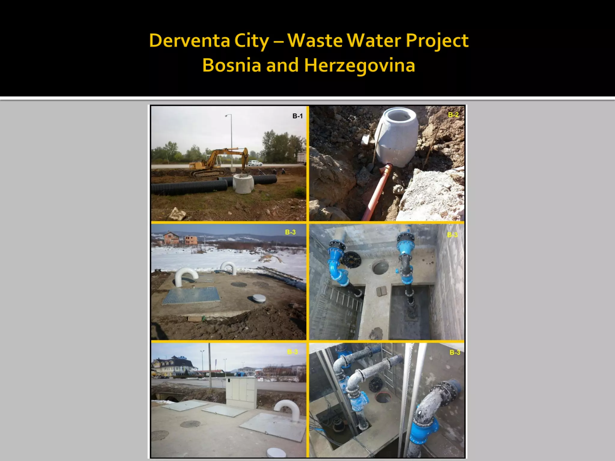
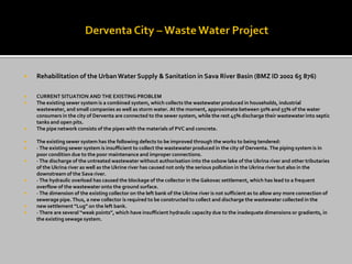
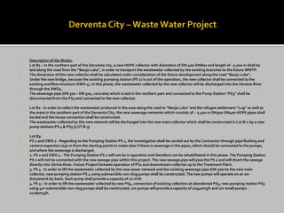
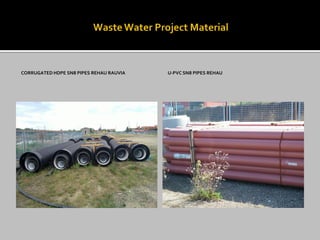
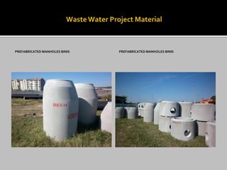
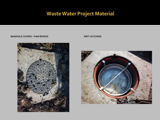
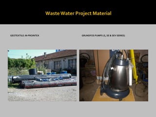
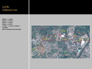
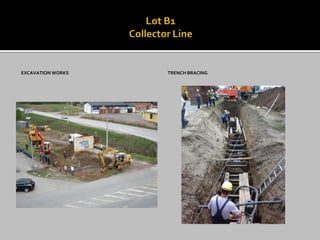
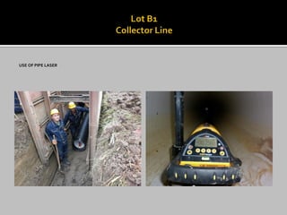
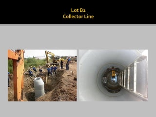
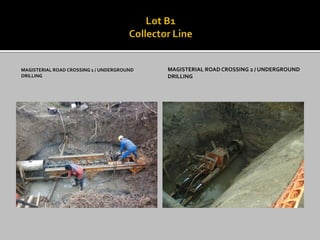
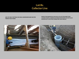
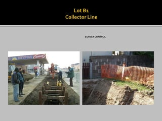
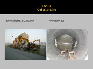
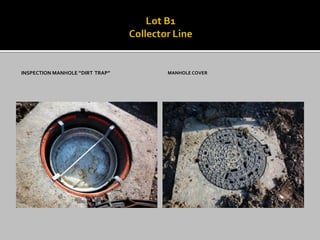
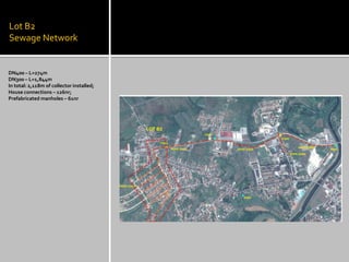
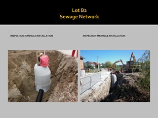
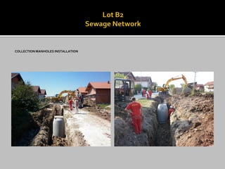
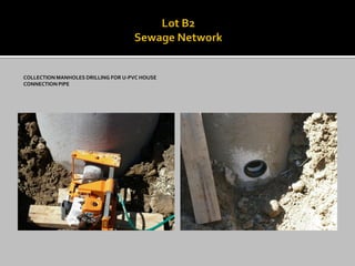
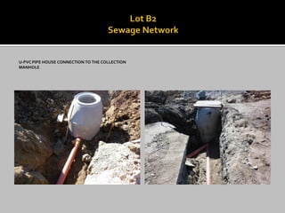
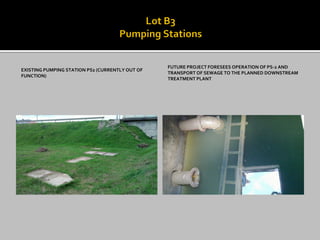
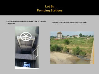
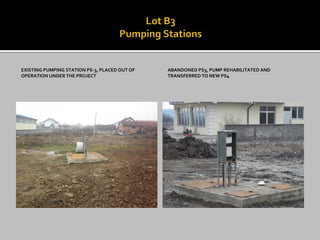
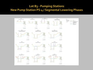
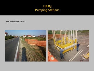
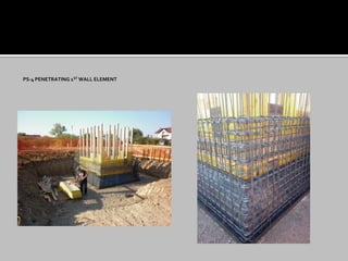
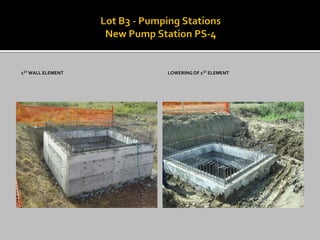
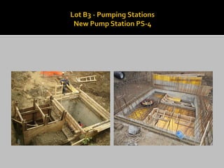
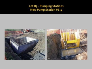
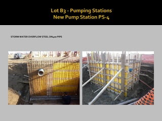
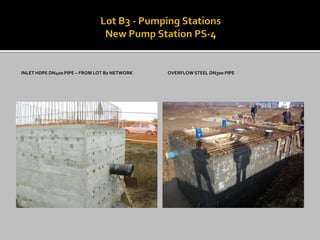
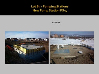
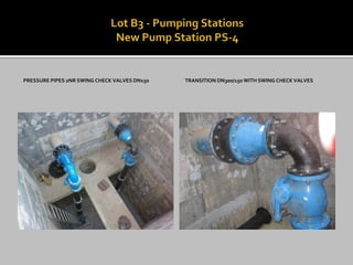
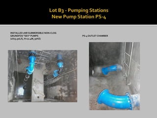
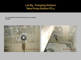
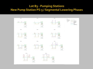
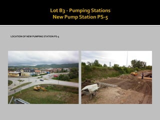
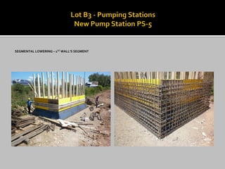
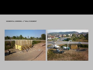
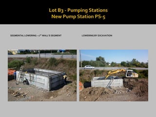
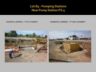
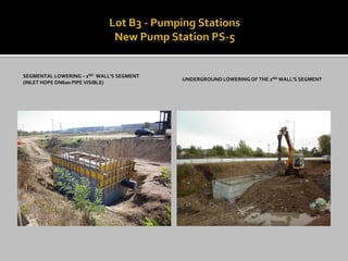
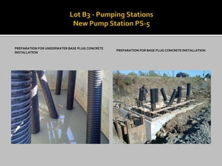
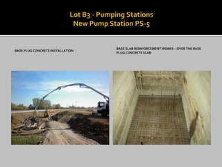
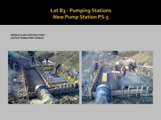
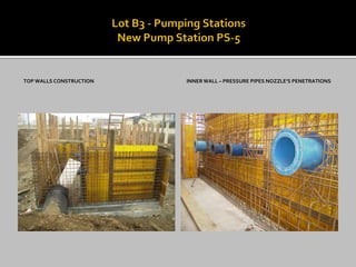
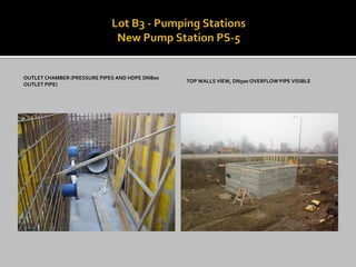
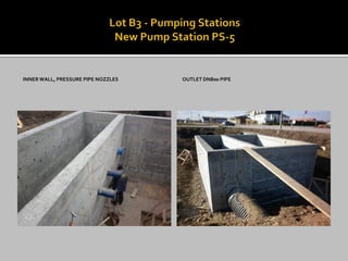
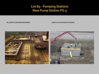
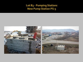
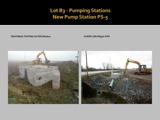
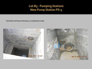
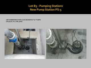
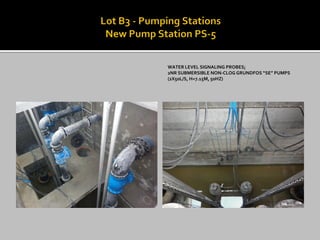
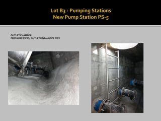
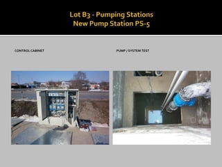
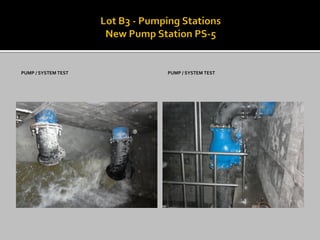
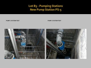
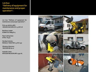

The document summarizes rehabilitation works for the urban water supply and sewer system in Derventa, Bosnia and Herzegovina. It describes the existing combined sewer system that collects wastewater, stormwater, and industrial wastewater, of which only around 50% of the city is connected. The proposed works include constructing a new sewer collector network (Lot B1 and B2) and upgrading existing pumping stations PS1, PS2, PS3 and building new pumping stations PS4 and PS5 to improve wastewater management and prevent pollution of nearby waterways. Equipment is also procured to support maintenance and operation of the rehabilitated system.


