Collection and Estimationof
Sewage
Eng. CHU DICKSON
(M.Eng in Environmental Engineering)
chnkoli@gmail.com
WASTE MANAGEMENT AND SANITATION
FACILITIES
2.
Course Content
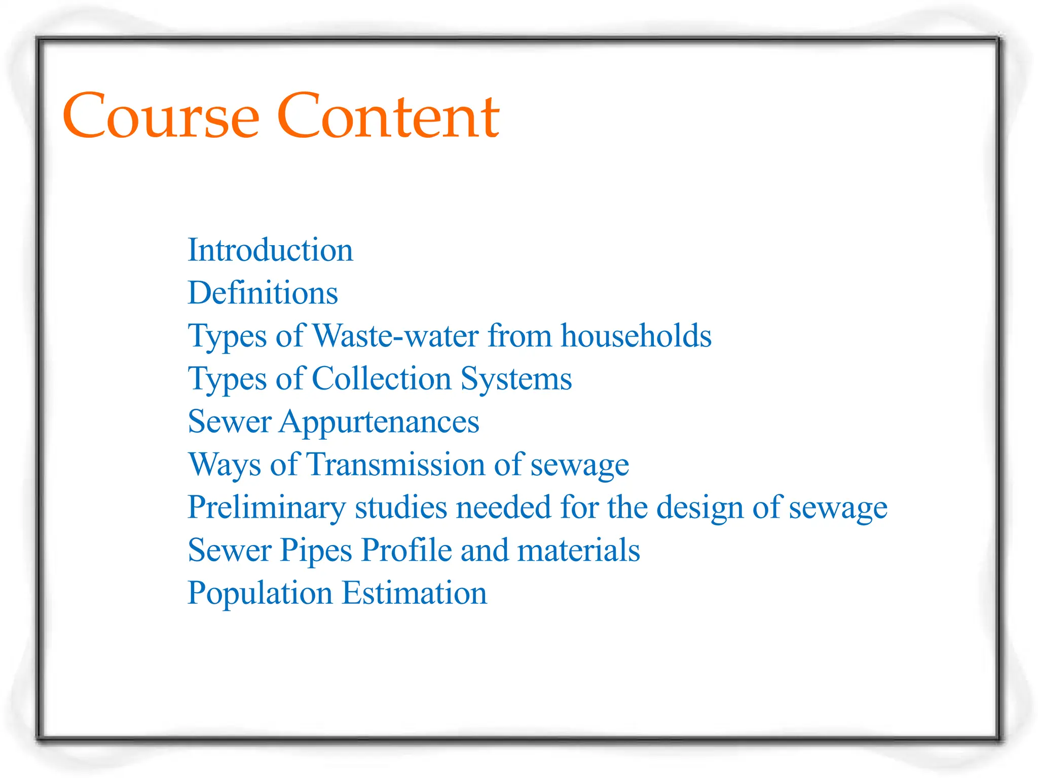
Introduction
Definitions
Types ofWaste-water from households
Types of Collection Systems
Sewer Appurtenances
Ways of Transmission of sewage
Preliminary studies needed for the design of sewage
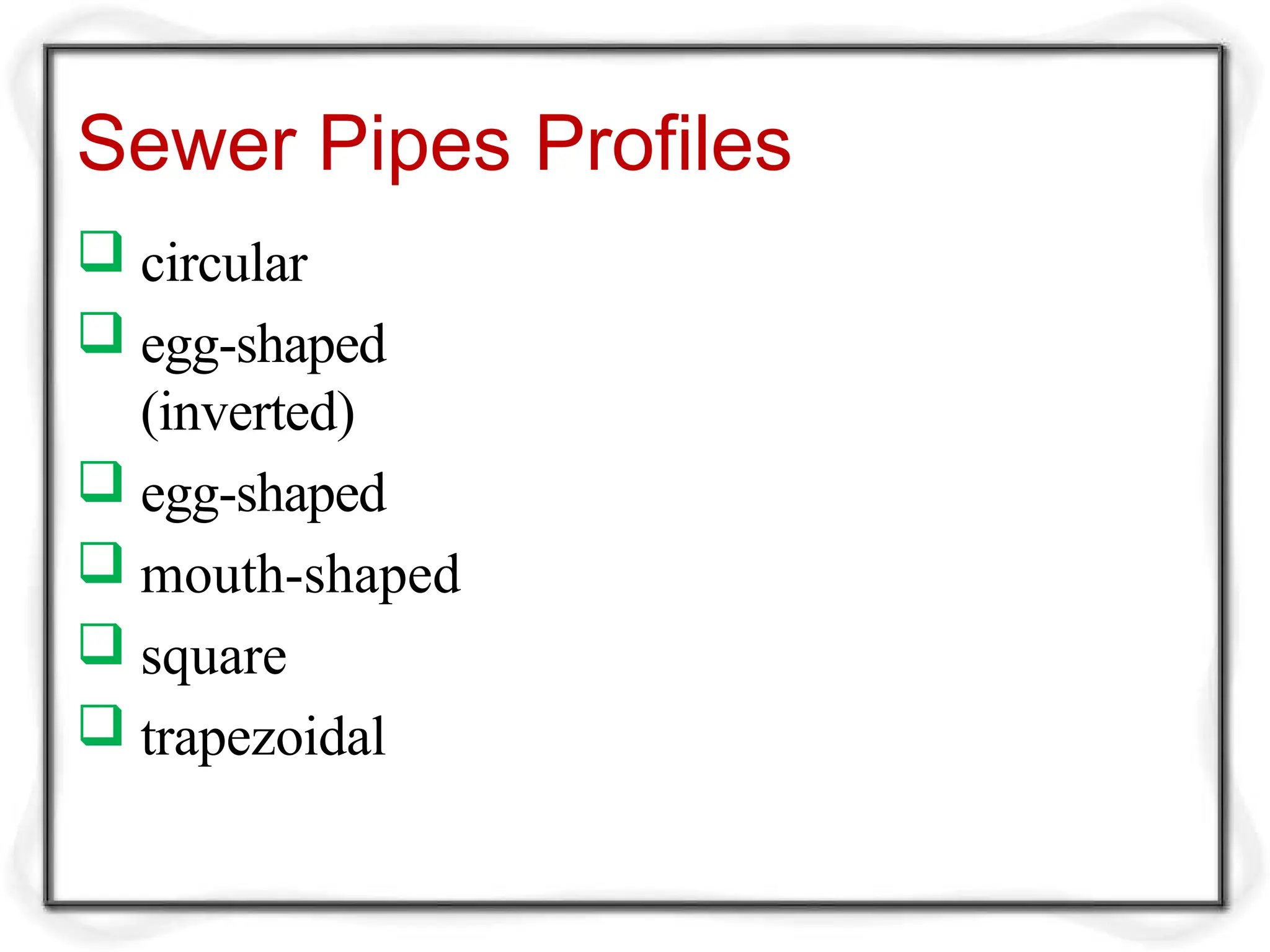
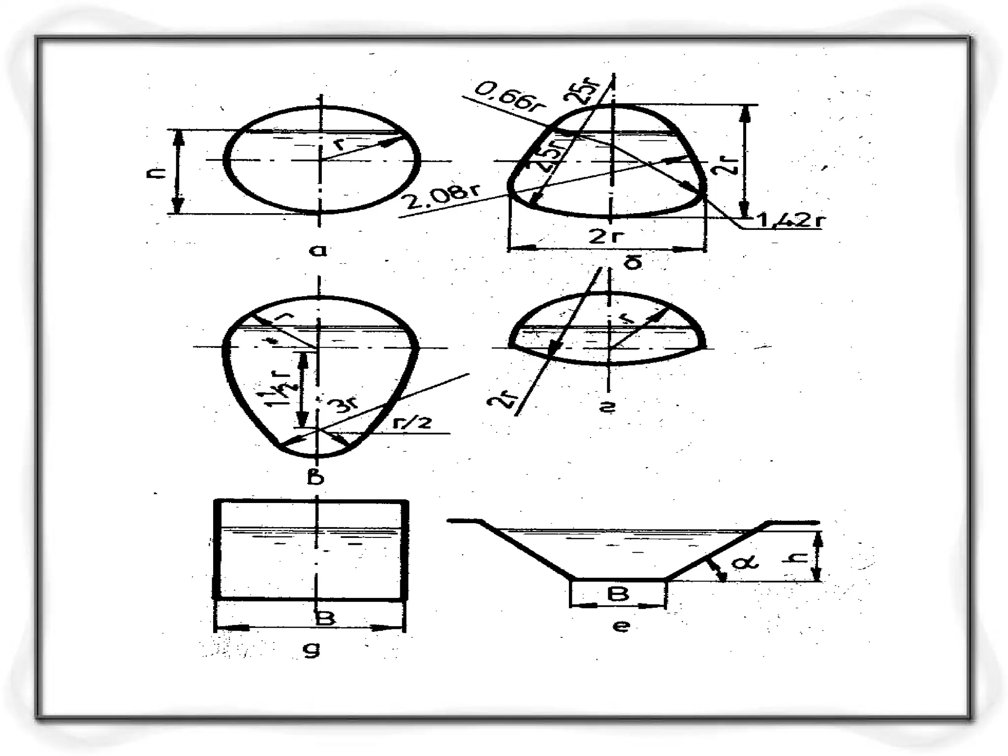
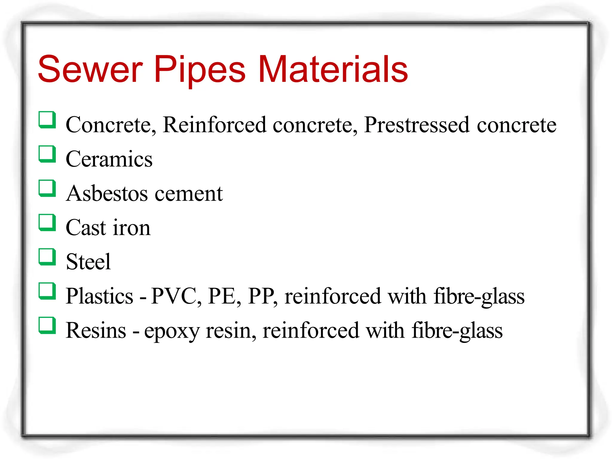
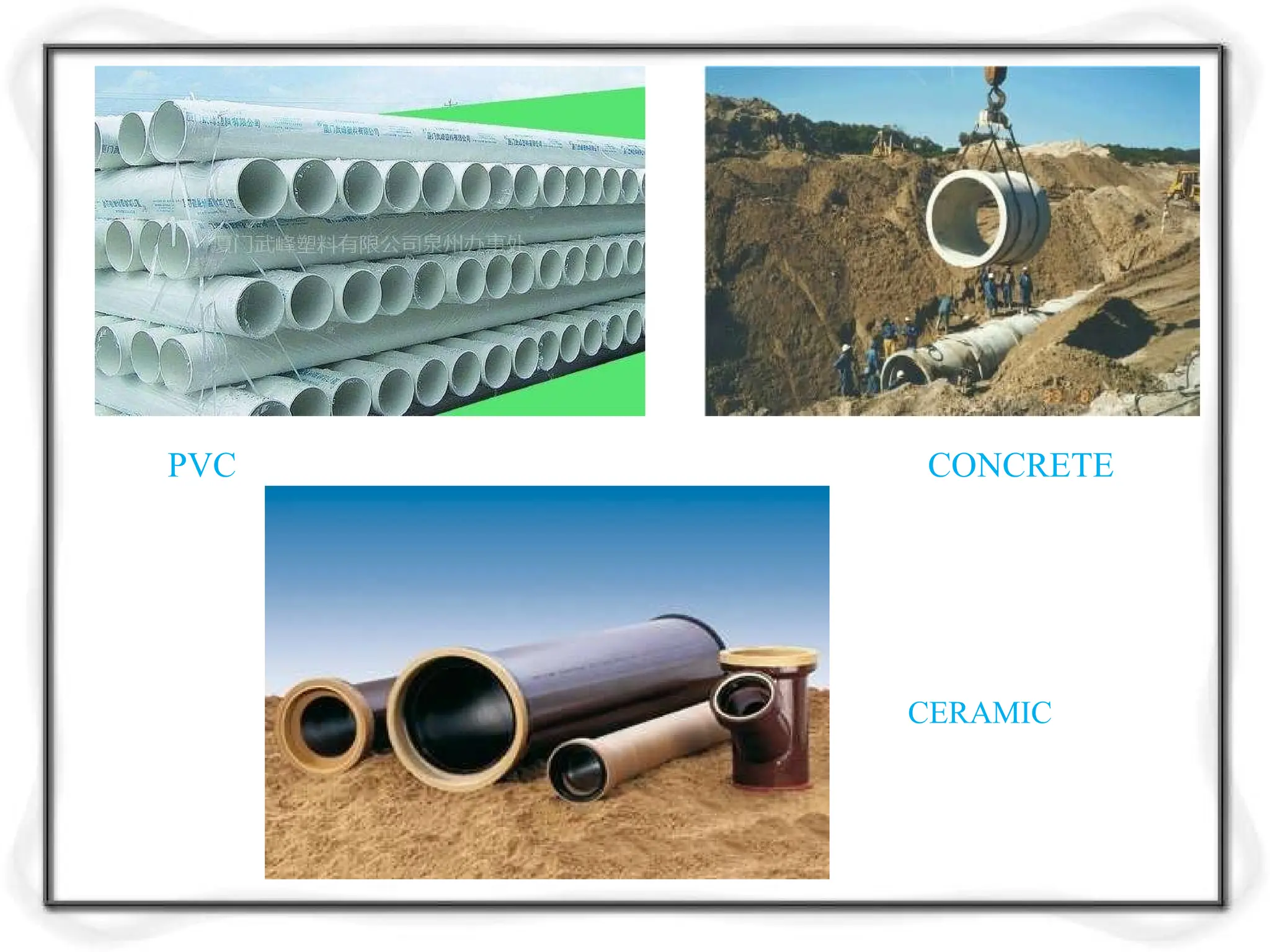
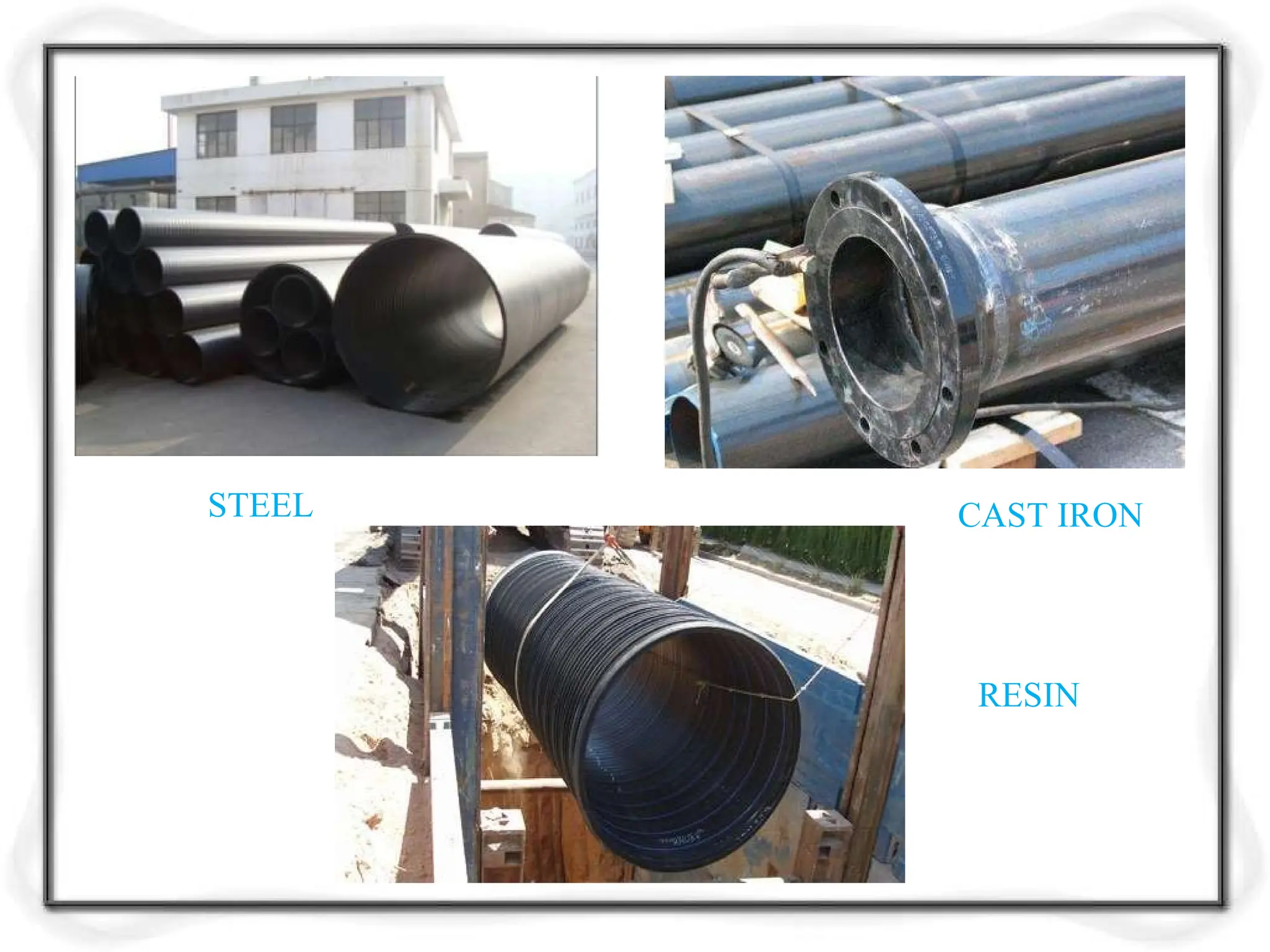
Sewer Pipes Profile and materials
Population Estimation
3.
Introduction
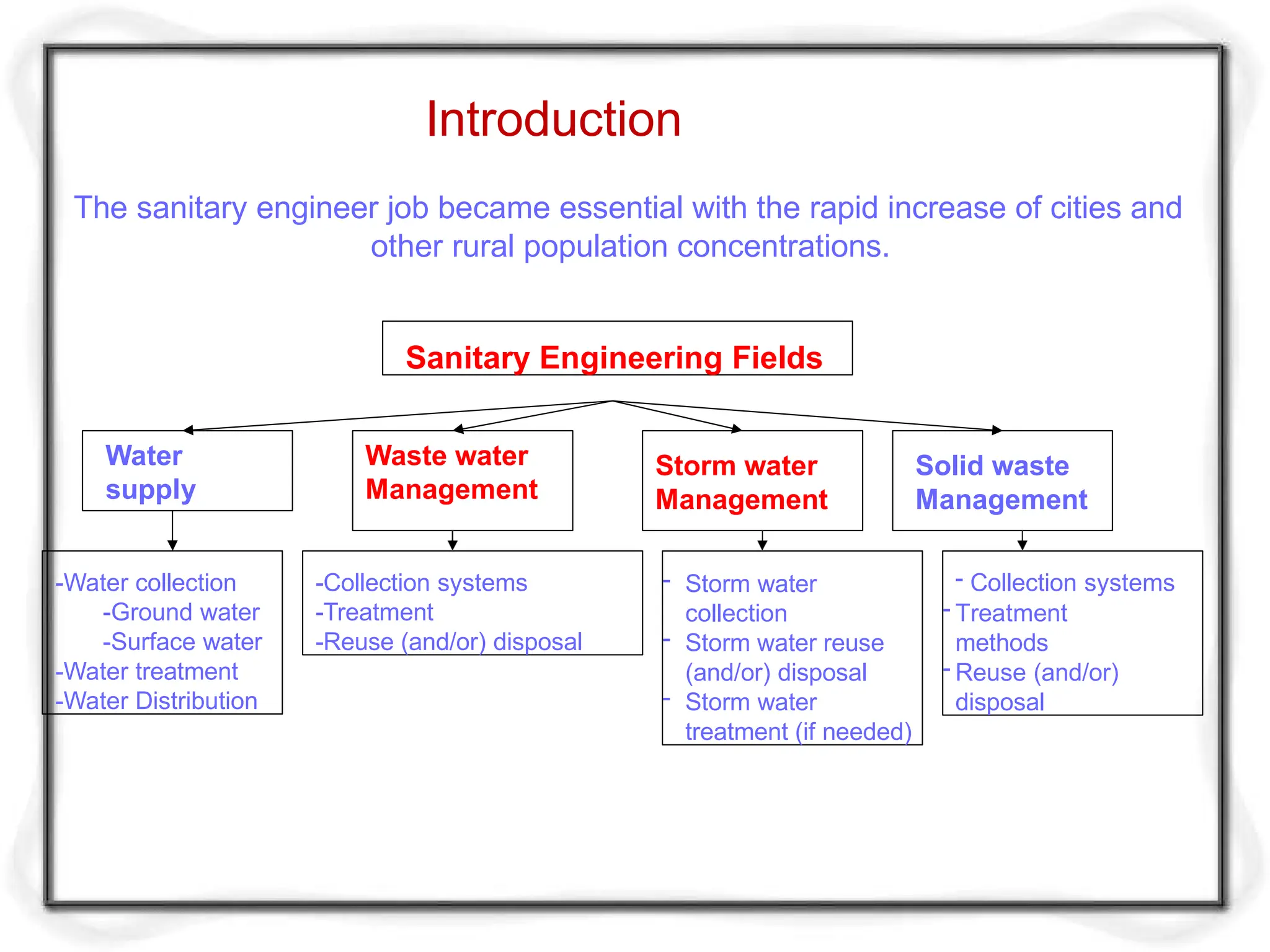
The sanitary engineerjob became essential with the rapid increase of cities and
other rural population concentrations.
Sanitary Engineering Fields
Water
supply
-Collection systems
-Treatment
-Reuse (and/or) disposal
- Storm water
collection
- Storm water reuse
(and/or) disposal
- Storm water
treatment (if needed)
-Water collection
-Ground water
-Surface water
-Water treatment
-Water Distribution
Waste water
Management
Storm water
Management
Solid waste
Management
- Collection systems
- Treatment
methods
- Reuse (and/or)
disposal
4.
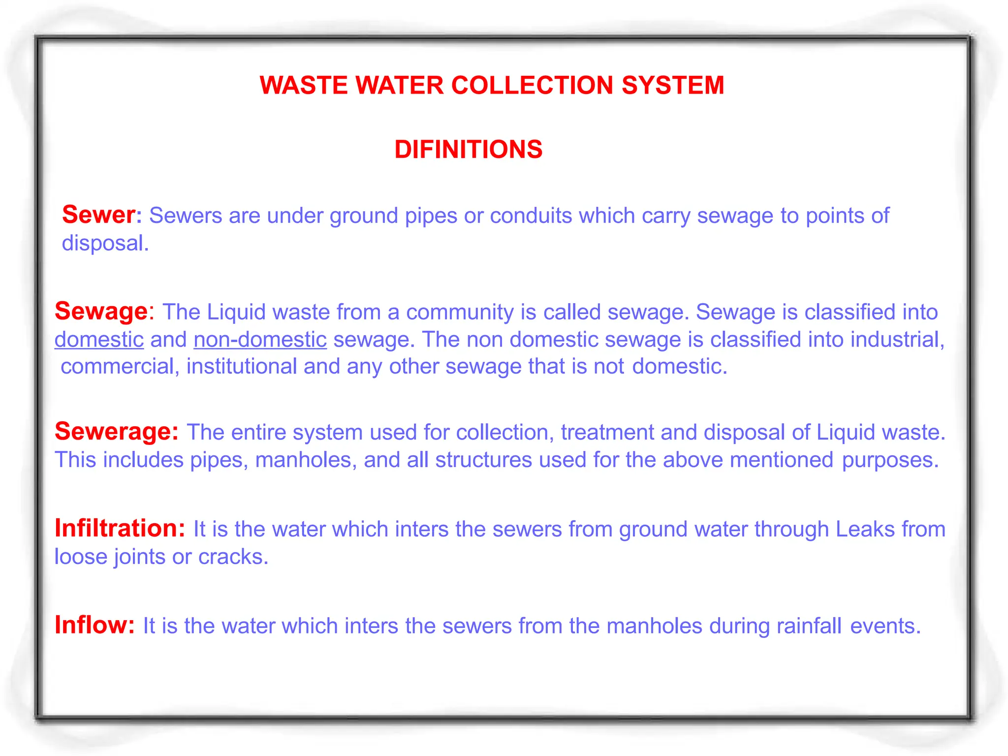
WASTE WATER COLLECTIONSYSTEM
DIFINITIONS
Sewer: Sewers are under ground pipes or conduits which carry sewage to points of
disposal.
Sewage: The Liquid waste from a community is called sewage. Sewage is classified into
domestic and non-domestic sewage. The non domestic sewage is classified into industrial,
commercial, institutional and any other sewage that is not domestic.
Sewerage: The entire system used for collection, treatment and disposal of Liquid waste.
This includes pipes, manholes, and all structures used for the above mentioned purposes.
Infiltration: It is the water which inters the sewers from ground water through Leaks from
loose joints or cracks.
Inflow: It is the water which inters the sewers from the manholes during rainfall events.
5.
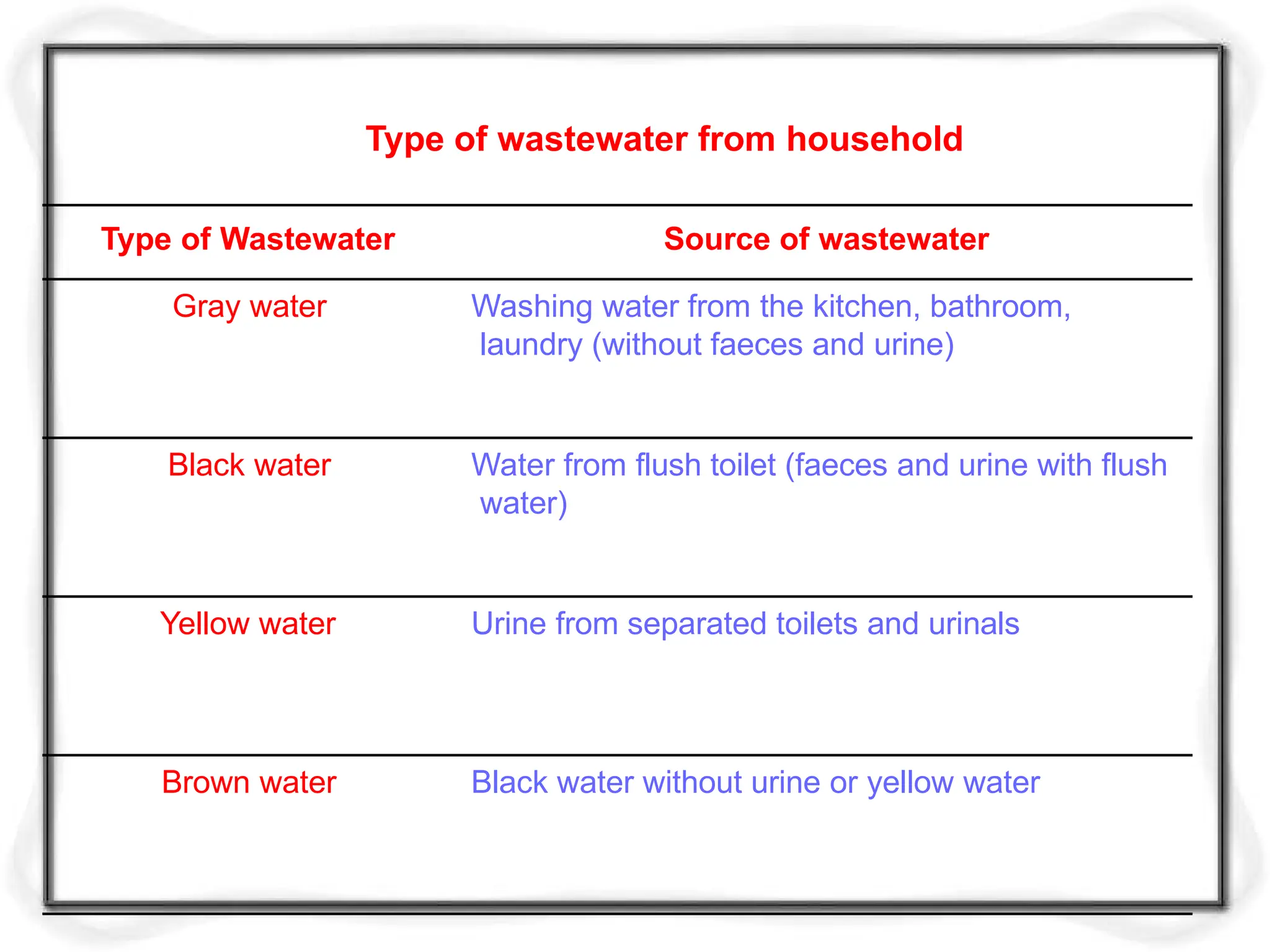
Urine from separatedtoilets and urinals
Yellow water
Water from flush toilet (faeces and urine with flush
water)
Black water
Black water without urine or yellow water
Brown water
Washing water from the kitchen, bathroom,
laundry (without faeces and urine)
Gray water
Type of wastewater from household
Type of Wastewater Source of wastewater
6.
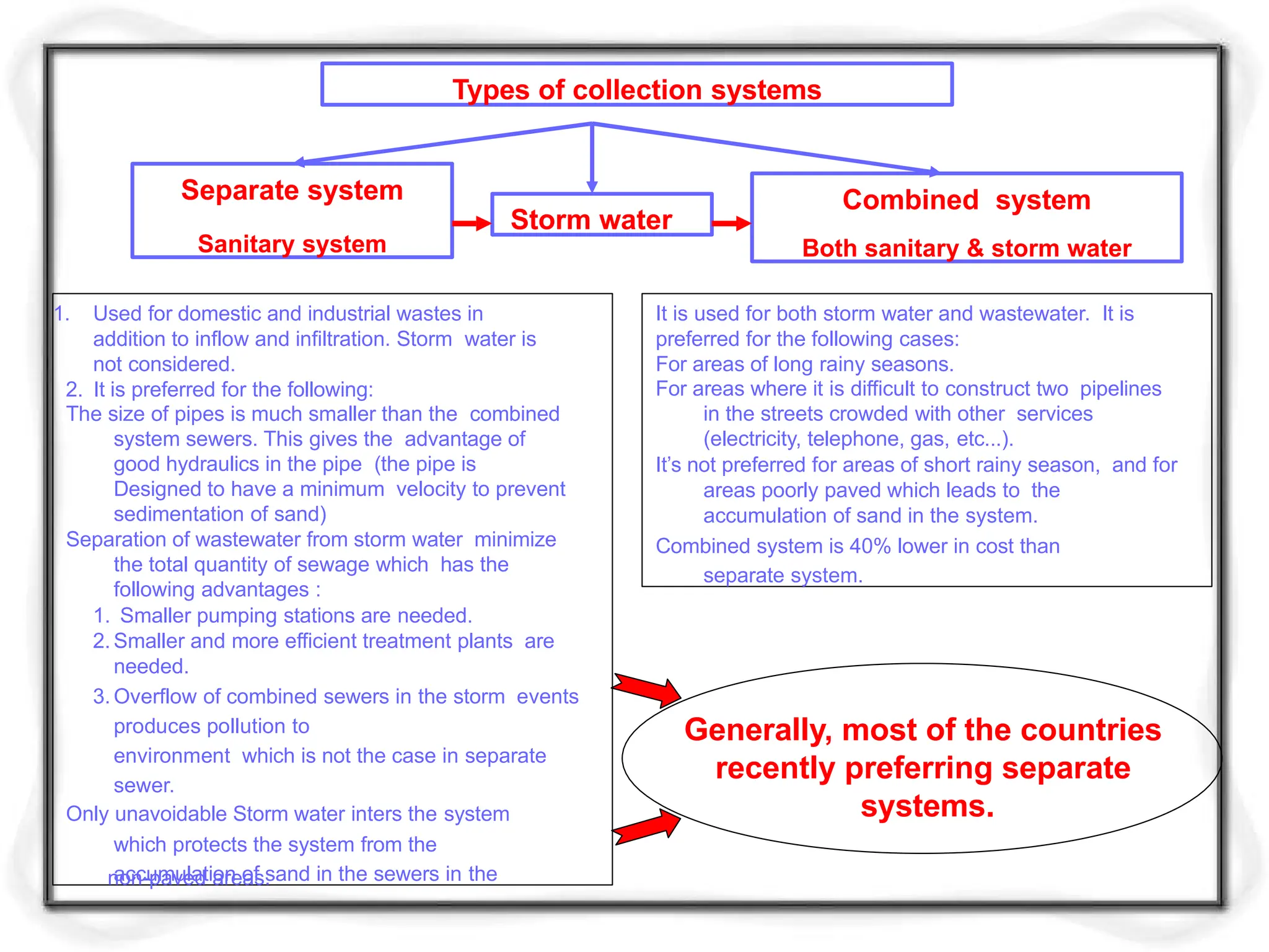
Types of collectionsystems
Separate system
Sanitary system
Combined system
Both sanitary & storm water
1. Used for domestic and industrial wastes in
addition to inflow and infiltration. Storm water is
not considered.
2. It is preferred for the following:
The size of pipes is much smaller than the combined
system sewers. This gives the advantage of
good hydraulics in the pipe (the pipe is
Designed to have a minimum velocity to prevent
sedimentation of sand)
Separation of wastewater from storm water minimize
the total quantity of sewage which has the
following advantages :
1. Smaller pumping stations are needed.
2.Smaller and more efficient treatment plants are
needed.
3.Overflow of combined sewers in the storm events
produces pollution to
environment which is not the case in separate
sewer.
Only unavoidable Storm water inters the system
which protects the system from the
accumulation of sand in the sewers in the
non-paved areas.
It is used for both storm water and wastewater. It is
preferred for the following cases:
For areas of long rainy seasons.
For areas where it is difficult to construct two pipelines
in the streets crowded with other services
(electricity, telephone, gas, etc...).
It’s not preferred for areas of short rainy season, and for
areas poorly paved which leads to the
accumulation of sand in the system.
Combined system is 40% lower in cost than
separate system.
Storm water
Generally, most of the countries
recently preferring separate
systems.
7.
Combined sewersystem
Sanitary sewers system
Storm sewers system
Types of Sewerage systems
8.
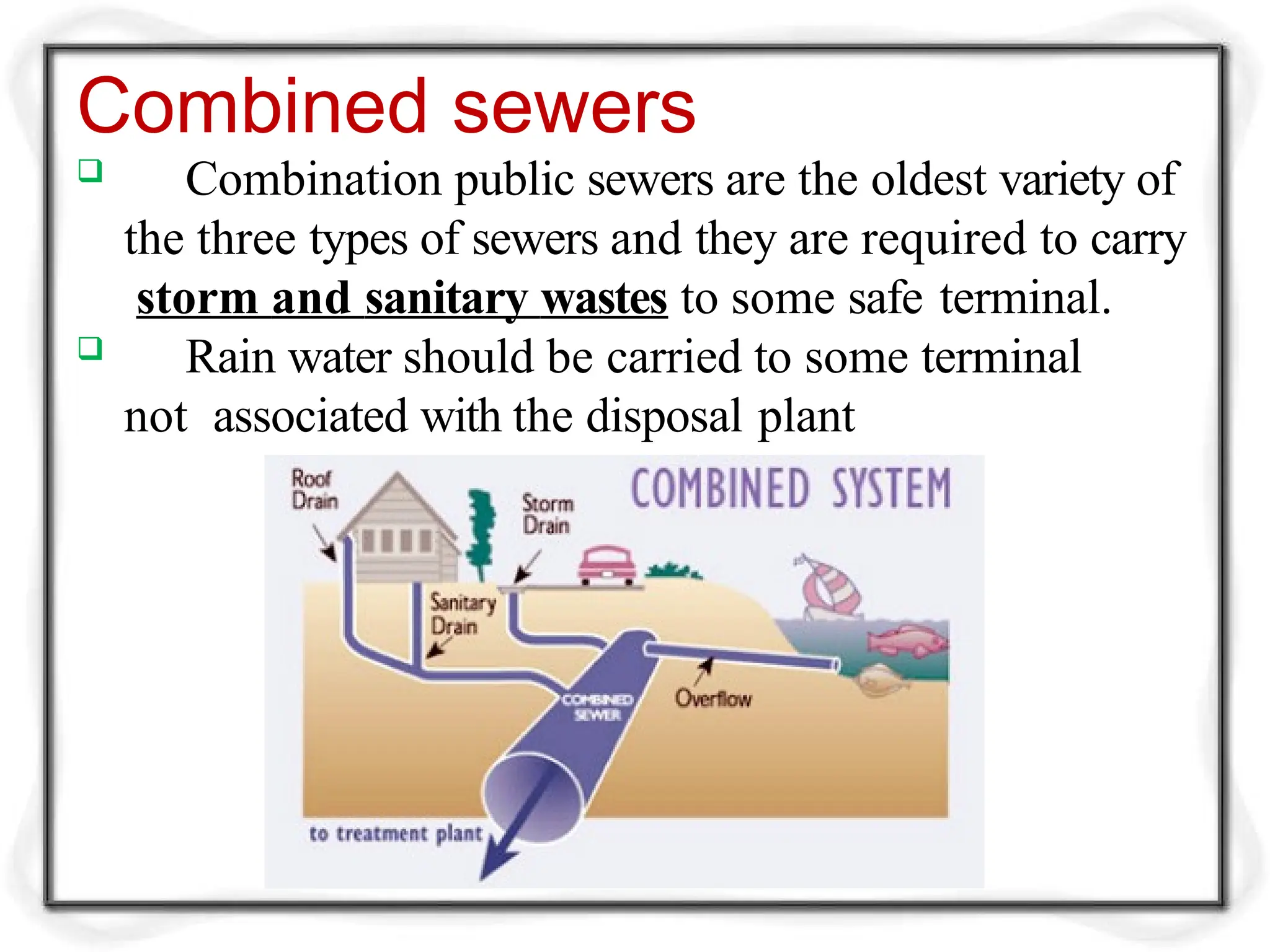
Combined sewers
Combinationpublic sewers are the oldest variety of
the three types of sewers and they are required to carry
storm and sanitary wastes to some safe terminal.
Rain water should be carried to some terminal
not associated with the disposal plant
9.
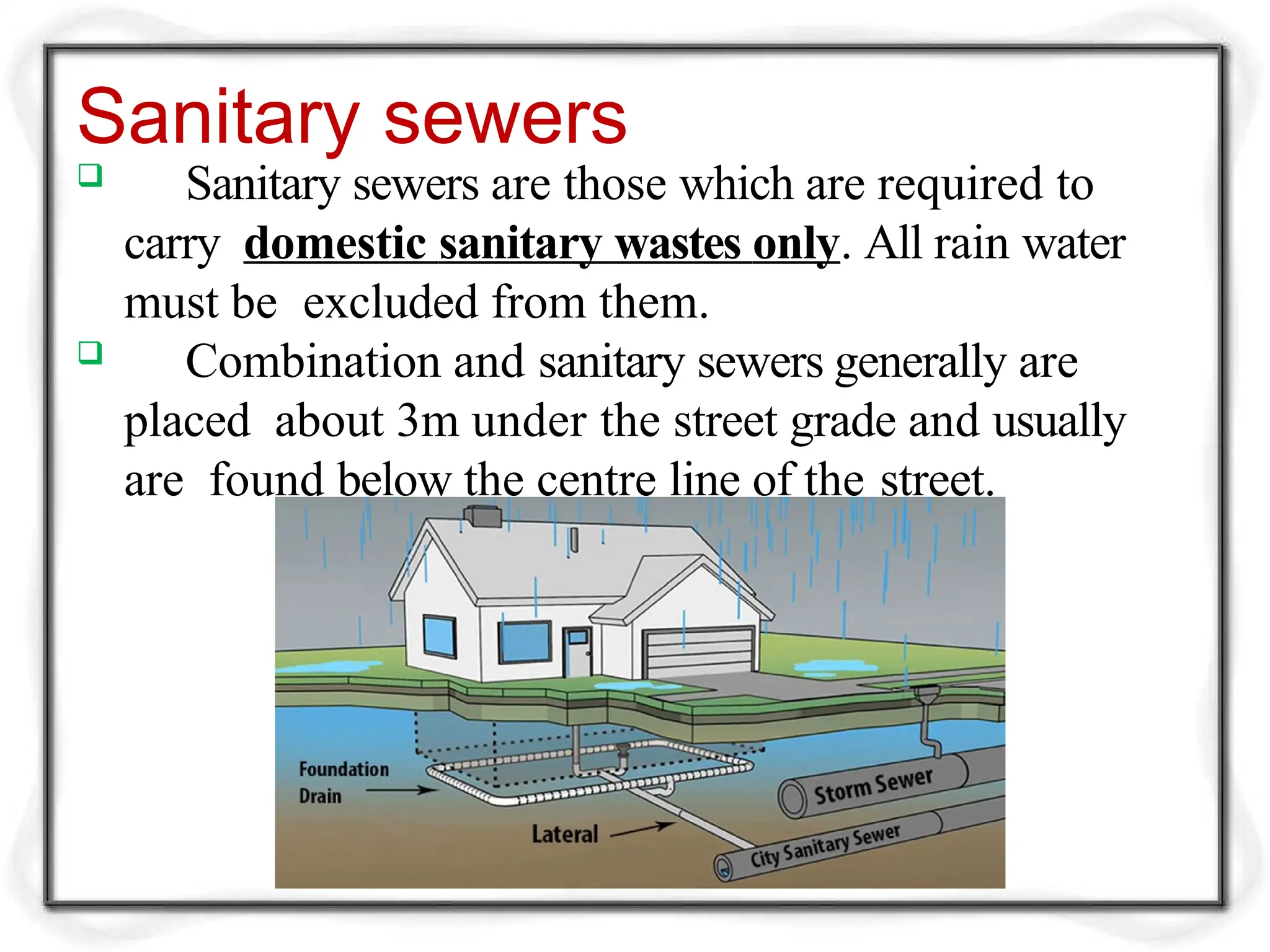
Sanitary sewers
Sanitarysewers are those which are required to
carry domestic sanitary wastes only. All rain water
must be excluded from them.
Combination and sanitary sewers generally are
placed about 3m under the street grade and usually
are found below the centre line of the street.
10.
Storm sewers
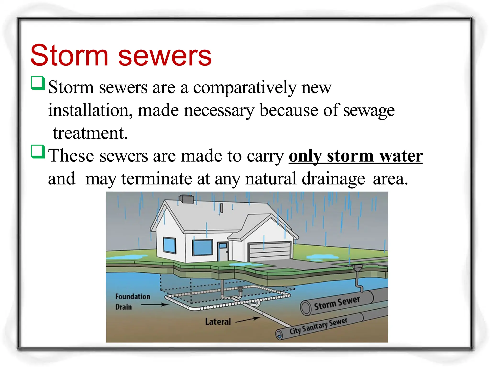
Storm sewersare a comparatively new
installation, made necessary because of sewage
treatment.
These sewers are made to carry only storm water
and may terminate at any natural drainage area.
11.
Sewer Appurtenances
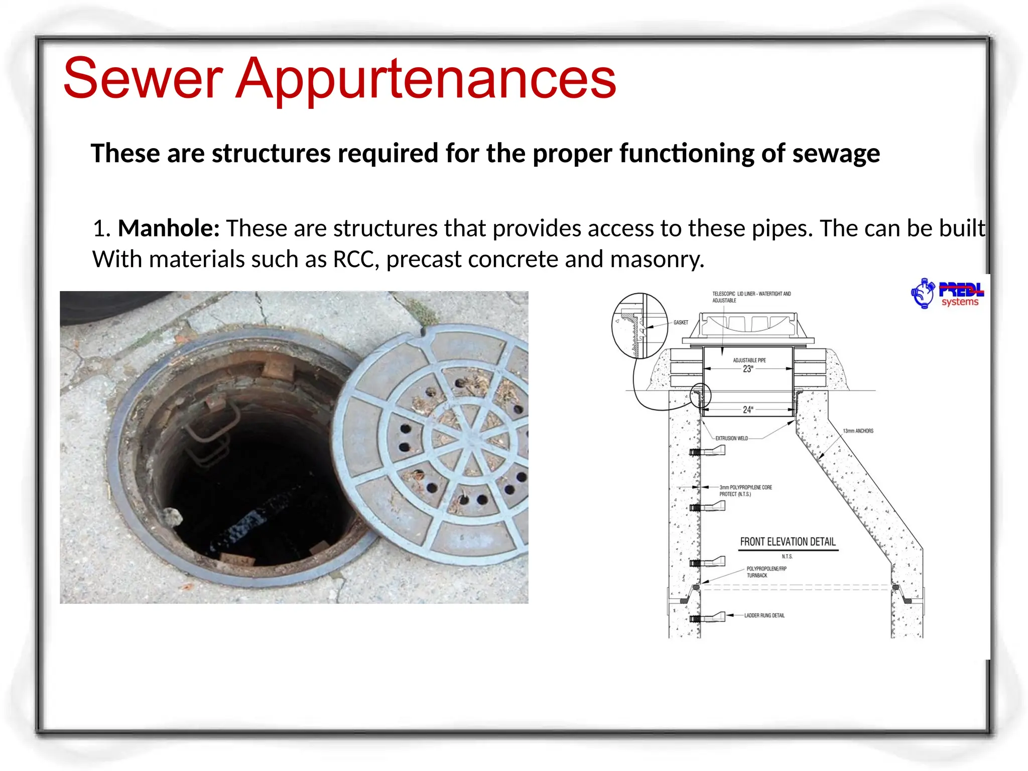
These arestructures required for the proper functioning of sewage
1. Manhole: These are structures that provides access to these pipes. The can be built
With materials such as RCC, precast concrete and masonry.
12.
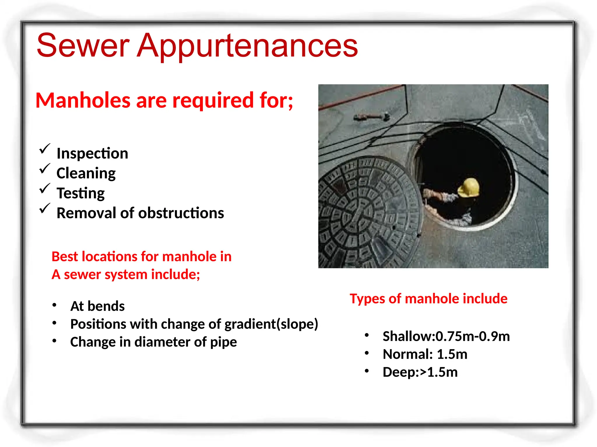
Manholes are requiredfor;
Sewer Appurtenances
Inspection
Cleaning
Testing
Removal of obstructions
Best locations for manhole in
A sewer system include;
• At bends
• Positions with change of gradient(slope)
• Change in diameter of pipe
Types of manhole include
• Shallow:0.75m-0.9m
• Normal: 1.5m
• Deep:>1.5m
13.
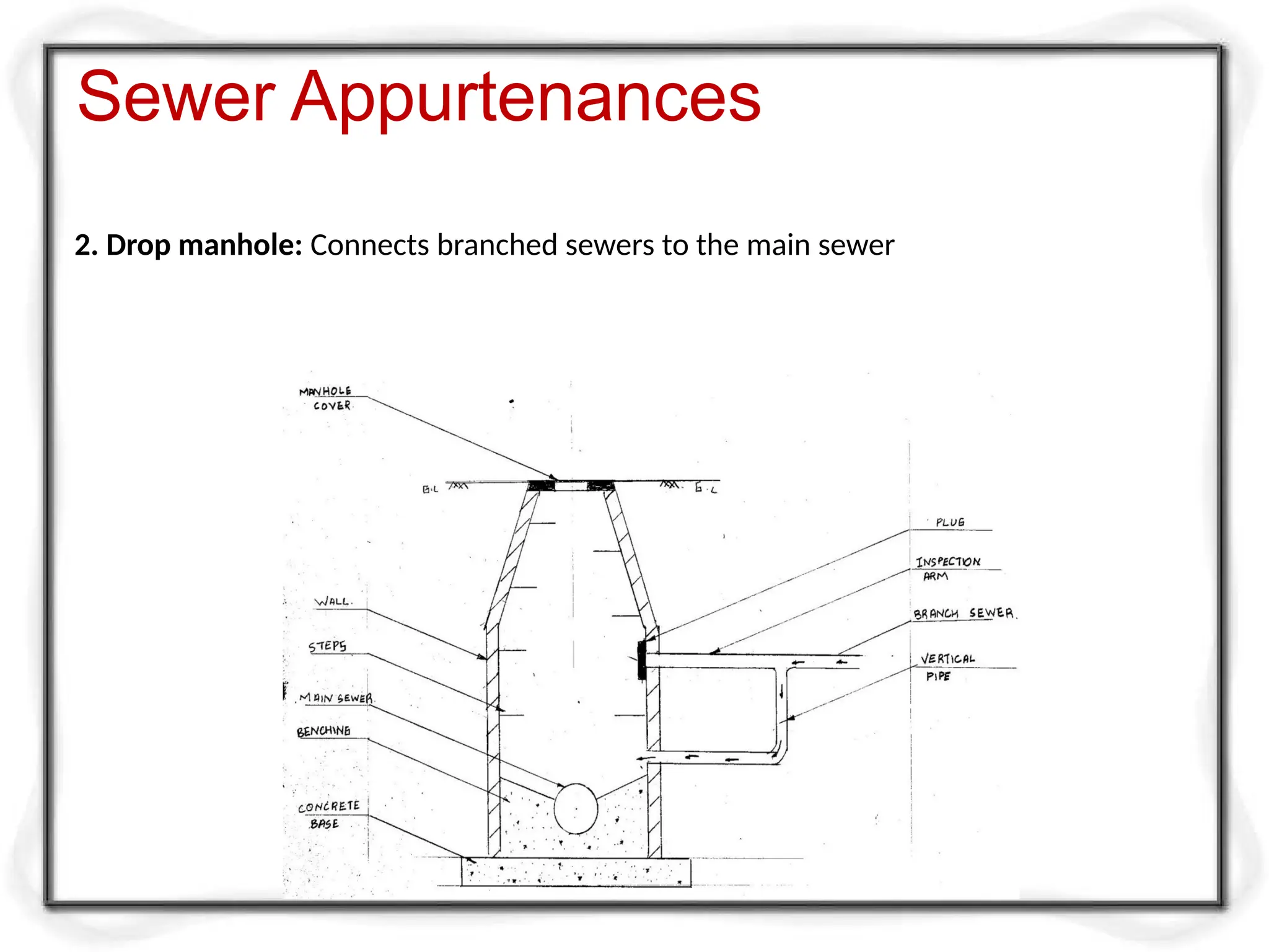
2. Drop manhole:Connects branched sewers to the main sewer
Sewer Appurtenances
14.
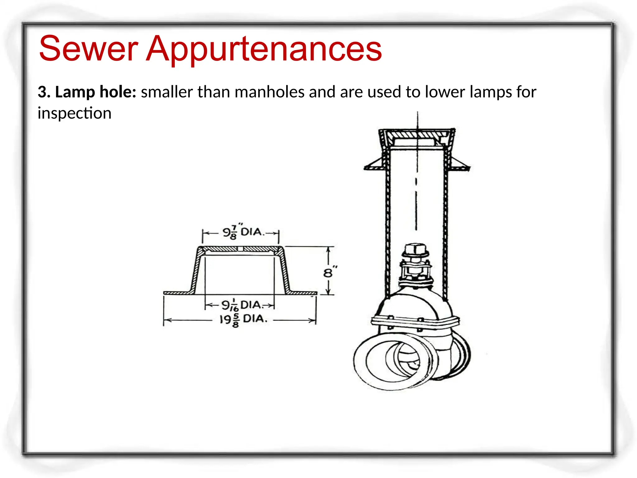
3. Lamp hole:smaller than manholes and are used to lower lamps for
inspection
Sewer Appurtenances
15.
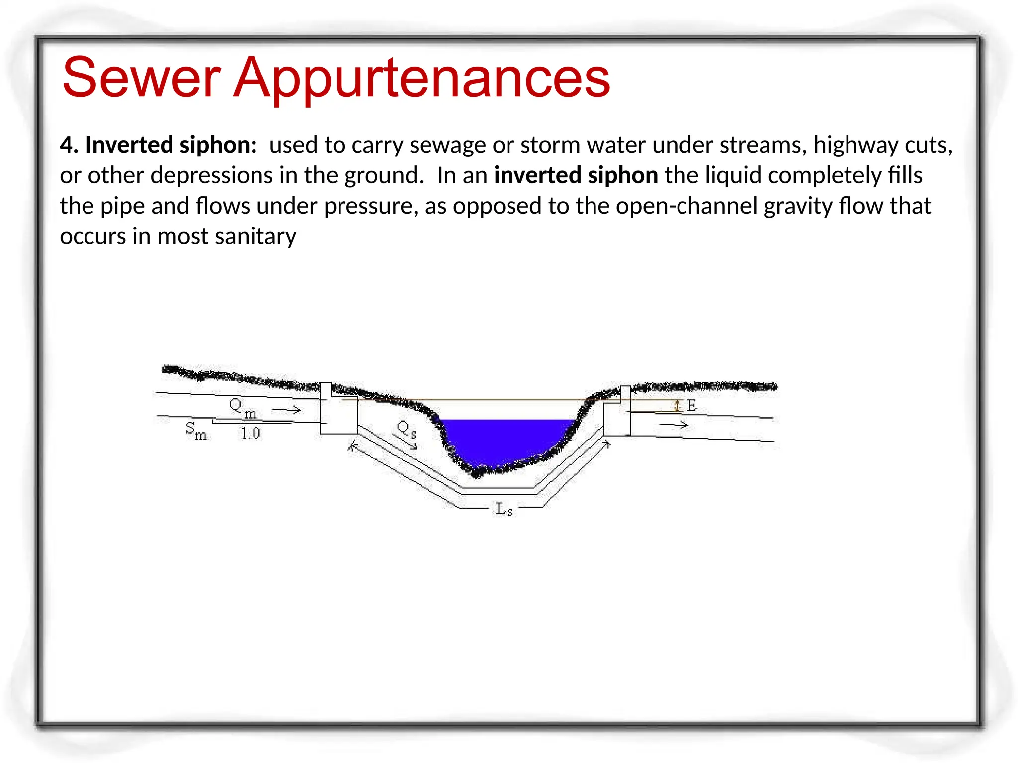
4. Inverted siphon:used to carry sewage or storm water under streams, highway cuts,
or other depressions in the ground. In an inverted siphon the liquid completely fills
the pipe and flows under pressure, as opposed to the open-channel gravity flow that
occurs in most sanitary
Sewer Appurtenances
16.
Sanitary sewer system
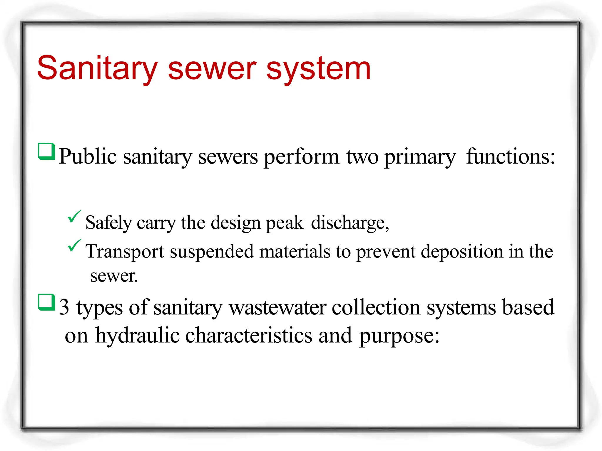
Publicsanitary sewers perform two primary functions:
Safely carry the design peak discharge,
Transport suspended materials to prevent deposition in the
sewer.
3 types of sanitary wastewater collection systems based
on hydraulic characteristics and purpose:
17.
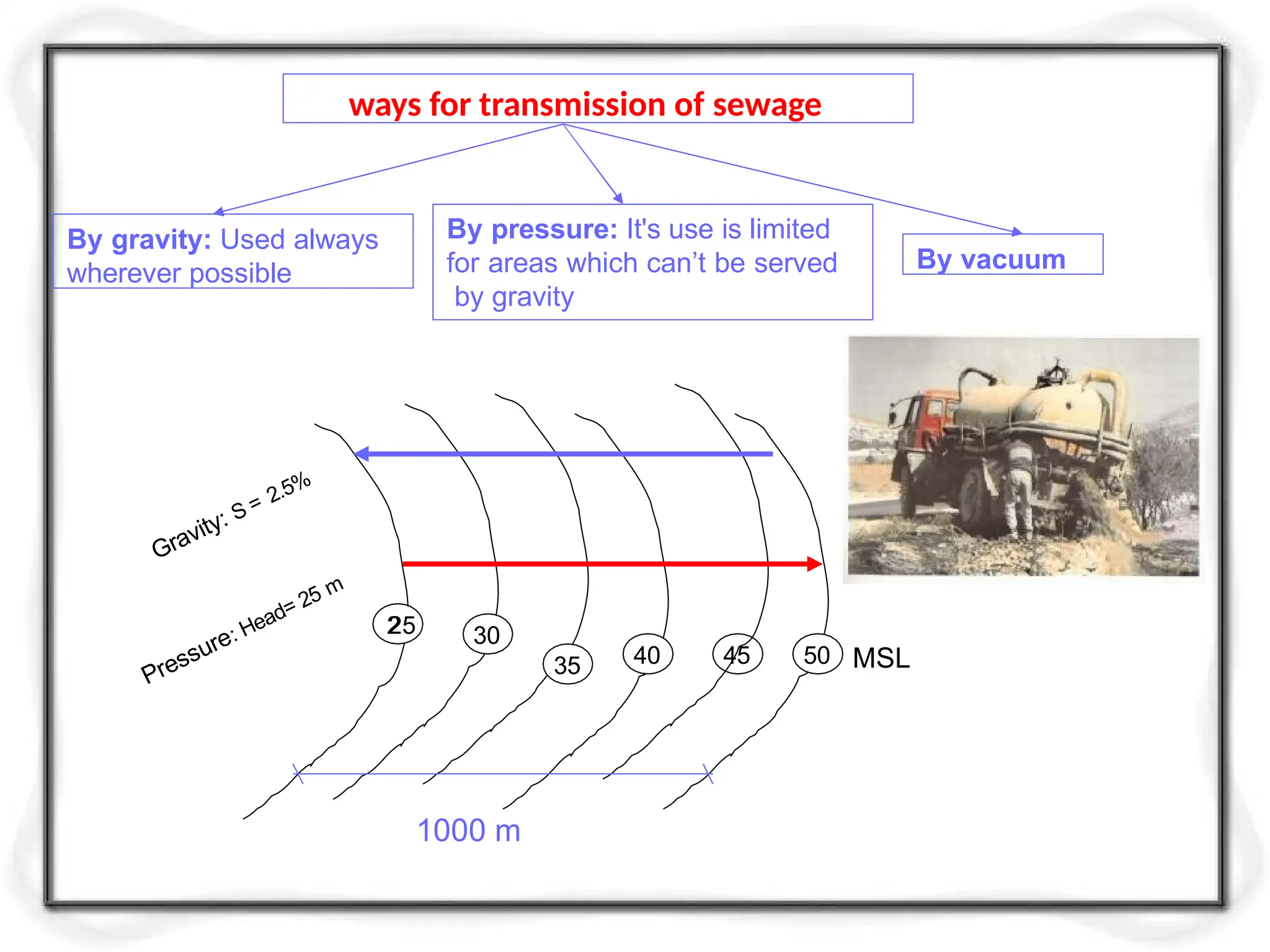
ways for transmissionof sewage
By gravity: Used always
wherever possible
By pressure: It's use is limited
for areas which can’t be served
by gravity
By vacuum
1000 m
Gravity: S = 2.5%
Pressure: Head= 25 m
2
25 30
35 40 45 50 MSL
18.
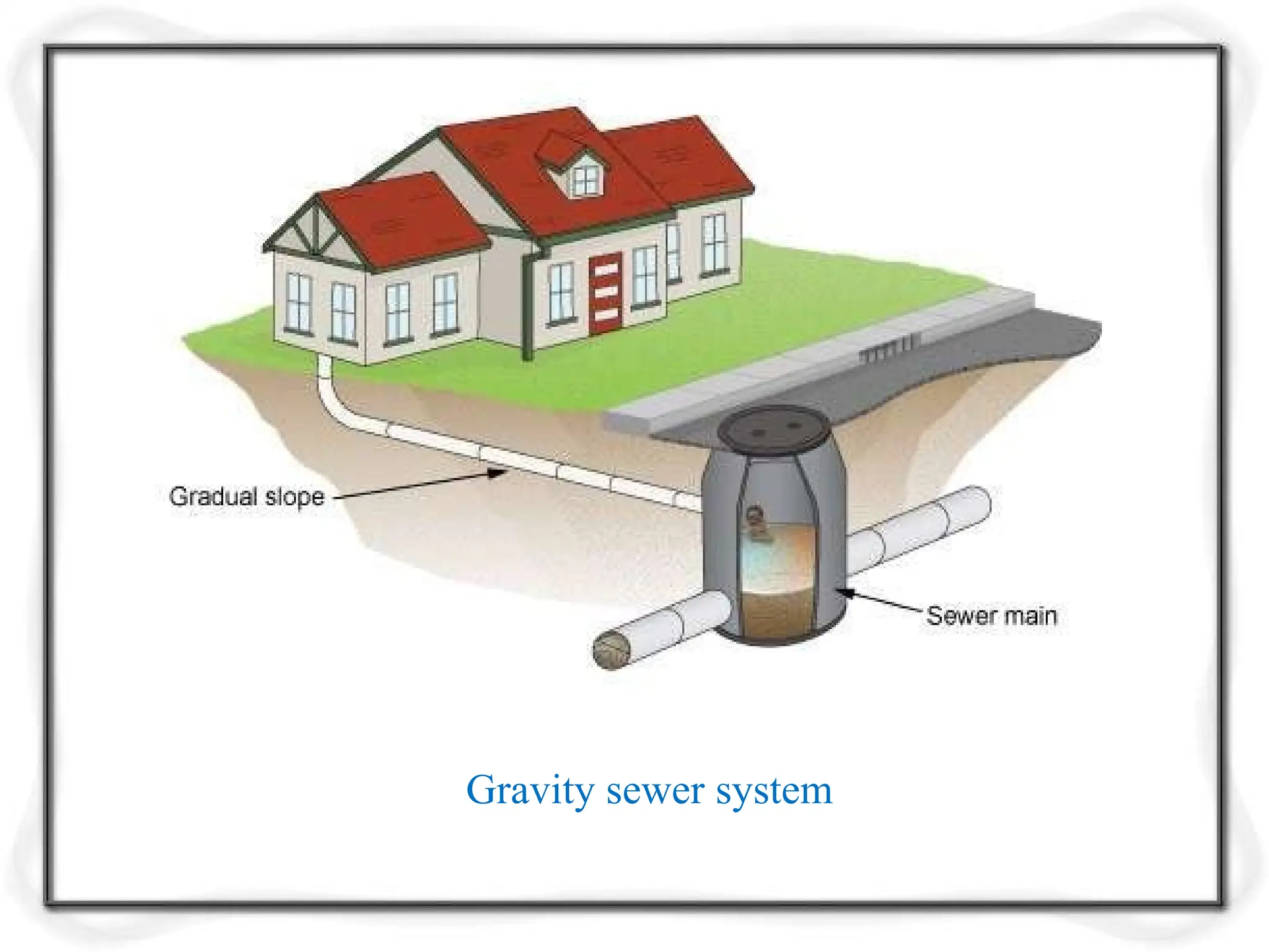
Gravity Sanitary Sewer
Most common.
Wastewater transported by gravity.
Used to collect wastewater from
residential, commercial, industrial, and institutional
sources.
Conveyance capacity allowances must be made
for groundwater infiltration and unavoidable
inflow.
Pressure (Pumped) SanitarySewer
Economical and environmentally friendly way
of collecting, transporting and disposing of
wastewater from households.
They are often used in areas when the landscape
is either very hilly or very flat, in areas that regularly
flood or have high water tables, or where it is
impractical to install other types of sewerage
systems.
21.
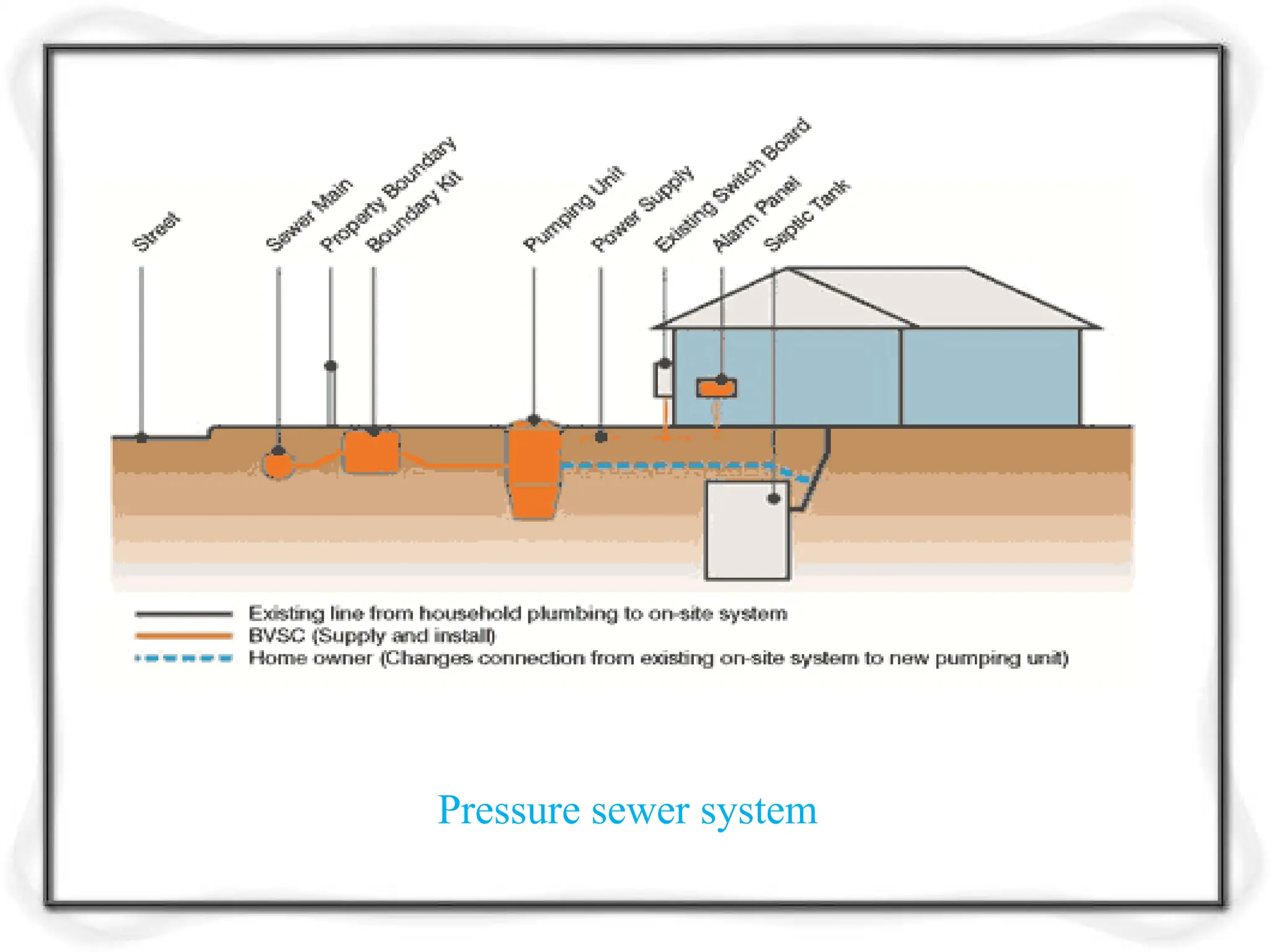
A pressuresewer system is made up of a network
of fully sealed pipes which are fed by pumping units
located at each connected property.
The pumping unit processes the household
wastewater and transfers it to the pressure sewer
located in the street via a small pipeline within the
property.
22.
The pressuresewer system is made of four
key elements. These elements are:
The pumping unit
The boundary valve kit
The house service line
The control panel
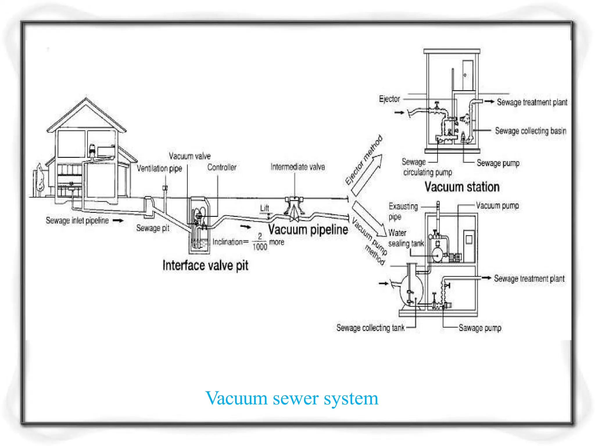
Vacuum Sewerage System
The wastewater is being delivered by a gravity
system to the pre tank of the domestic shaft.
While the pre-tank being filled, an electronic
sensor opens the interface valve.
During the opening air flows into the mixing
chamber and is being mixed with the wastewater and
leaves the valve flowing into the vacuum pipe network
as a water- air mixture.
25.
There arealso pneumatically controlled valves
that open and close depending on the vacuum in the
pipe network.
The vacuum pump produces a vacuum in the
wastewater collection tank as well as the pipe network
by which the wastewater is sucked from the pipe
network to the collection tank at the pumping station.
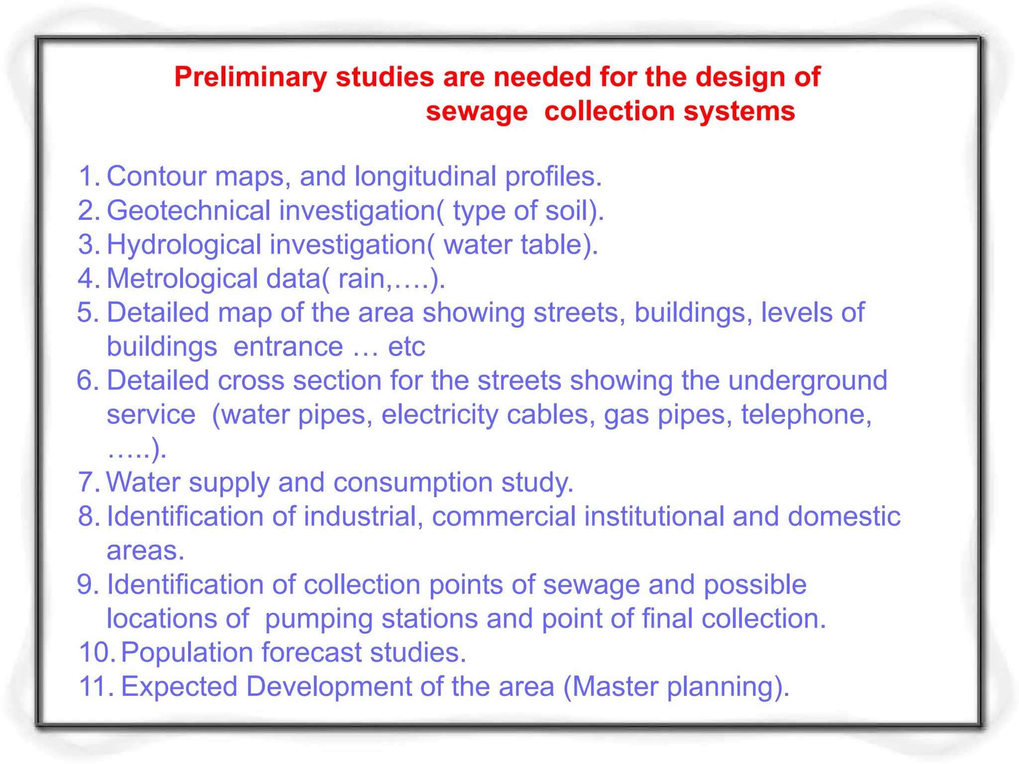
Preliminary studies areneeded for the design of
sewage collection systems
1. Contour maps, and longitudinal profiles.
2. Geotechnical investigation( type of soil).
3. Hydrological investigation( water table).
4. Metrological data( rain,….).
5. Detailed map of the area showing streets, buildings, levels of
buildings entrance … etc
6. Detailed cross section for the streets showing the underground
service (water pipes, electricity cables, gas pipes, telephone,
…..).
7. Water supply and consumption study.
8. Identification of industrial, commercial institutional and domestic
areas.
9. Identification of collection points of sewage and possible
locations of pumping stations and point of final collection.
10.Population forecast studies.
11. Expected Development of the area (Master planning).
Design approach
Wheredoes the wastewater come from?
How much wastewater flow is there going to
be?
How is the wastewater going to be removed
and treated?
Two main categories:
Sanitary Wastewater
Wastewater from residential, commercial, institutional and
industrial sources.
Storm water Runoff
Wastewater resulting from rainfall running off streets, roofs,
and other impervious surfaces.
36.
Components of aCommunity’s Wastewater
Domestic (sanitary) wastewater – wastewater
discharged from residences and from
commercial, institutional and similar facilities.
Industrial wastewater – wastewater in which industrial
wastes predominate.
37.
Infiltration/Inflow (I/I) –extraneous water that enters
the sewer system from the ground through various
means, and storm water that is discharged from
sources such as roof leaders, foundation drains, and
storm sewers.
Storm water – runoff resulting from rainfall and snow
melt
38.
Infiltration to SanitarySewer Systems
Groundwater/percolating water in the
subsurface entering a sewer system through:
Defective pipes
Leaking pipe joints
Poor connections
Cracked manhole walls etc.
39.
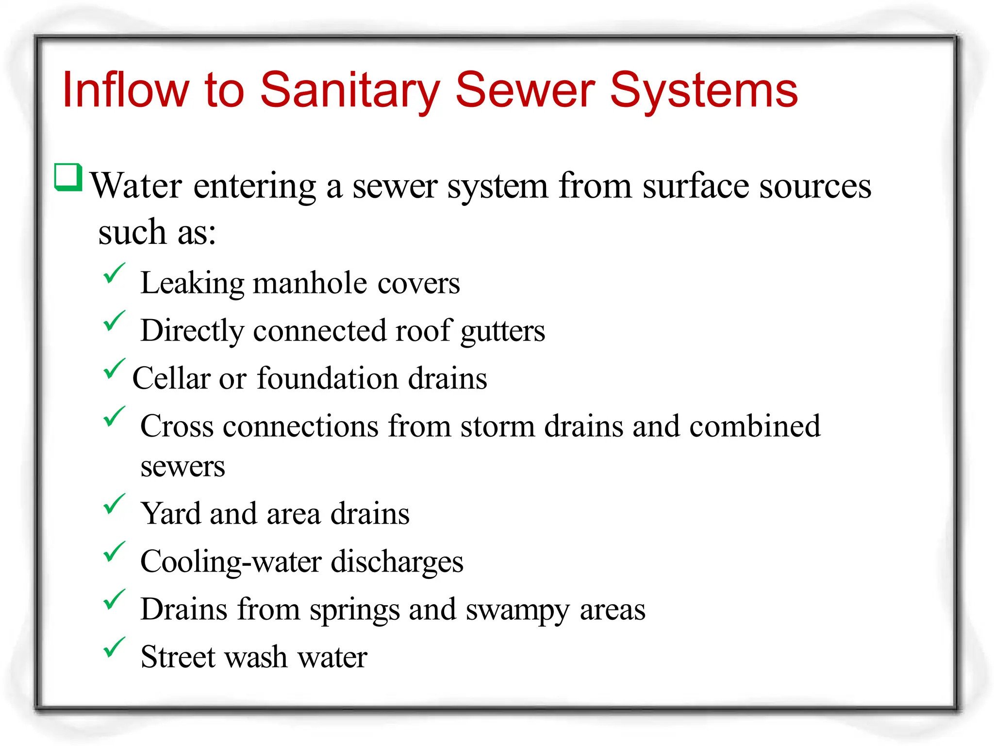
Inflow to SanitarySewer Systems
Water entering a sewer system from surface sources
such as:
Leaking manhole covers
Directly connected roof gutters
Cellar or foundation drains
Cross connections from storm drains and combined
sewers
Yard and area drains
Cooling-water discharges
Drains from springs and swampy areas
Street wash water
40.
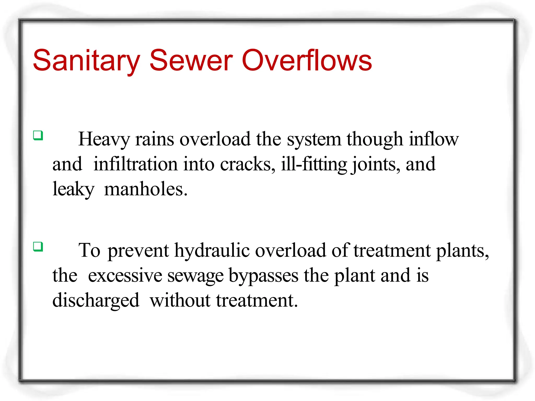
Sanitary Sewer Overflows
Heavy rains overload the system though inflow
and infiltration into cracks, ill-fitting joints, and
leaky manholes.
To prevent hydraulic overload of treatment plants,
the excessive sewage bypasses the plant and is
discharged without treatment.
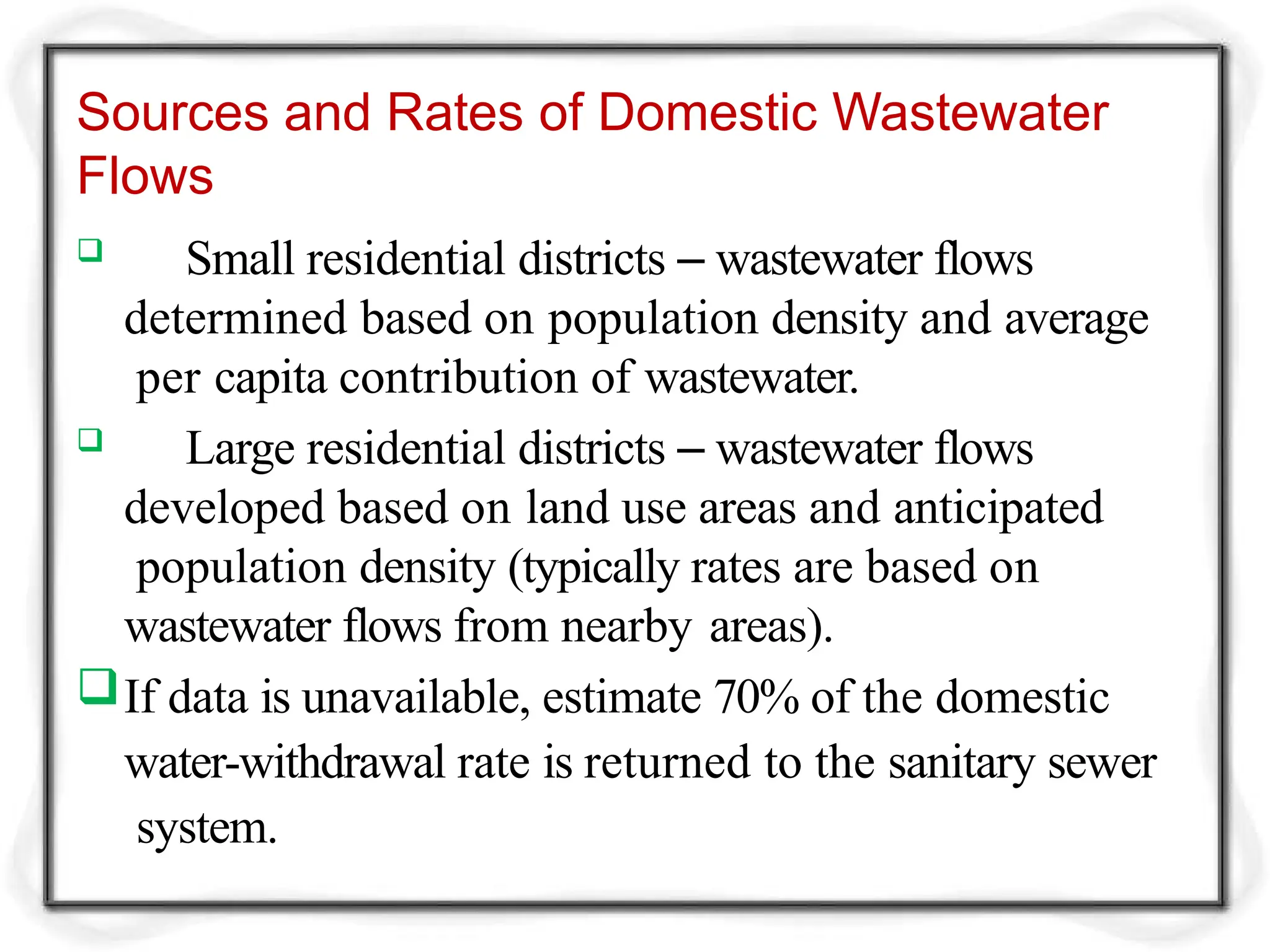
Sources and Ratesof Domestic Wastewater
Flows
Small residential districts – wastewater flows
determined based on population density and average
per capita contribution of wastewater.
Large residential districts – wastewater flows
developed based on land use areas and anticipated
population density (typically rates are based on
wastewater flows from nearby areas).
If data is unavailable, estimate 70% of the domestic
water-withdrawal rate is returned to the sanitary sewer
system.
43.
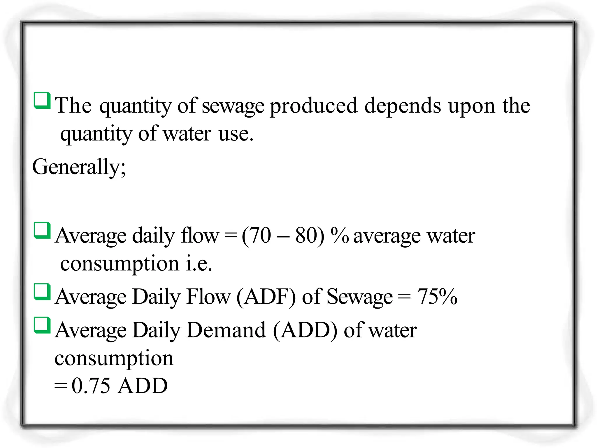
The quantity ofsewage produced depends upon the
quantity of water use.
Generally;
Average daily flow = (70 – 80) % average water
consumption i.e.
Average Daily Flow (ADF) of Sewage = 75%
Average Daily Demand (ADD) of water
consumption
= 0.75 ADD
44.
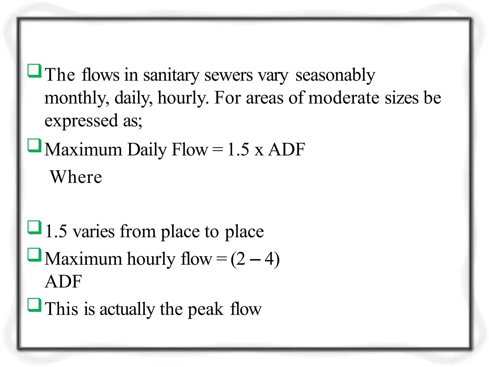
The flows insanitary sewers vary seasonably
monthly, daily, hourly. For areas of moderate sizes be
expressed as;
Maximum Daily Flow = 1.5 x ADF
Where
1.5 varies from place to place
Maximum hourly flow = (2 – 4)
ADF
This is actually the peak flow
45.
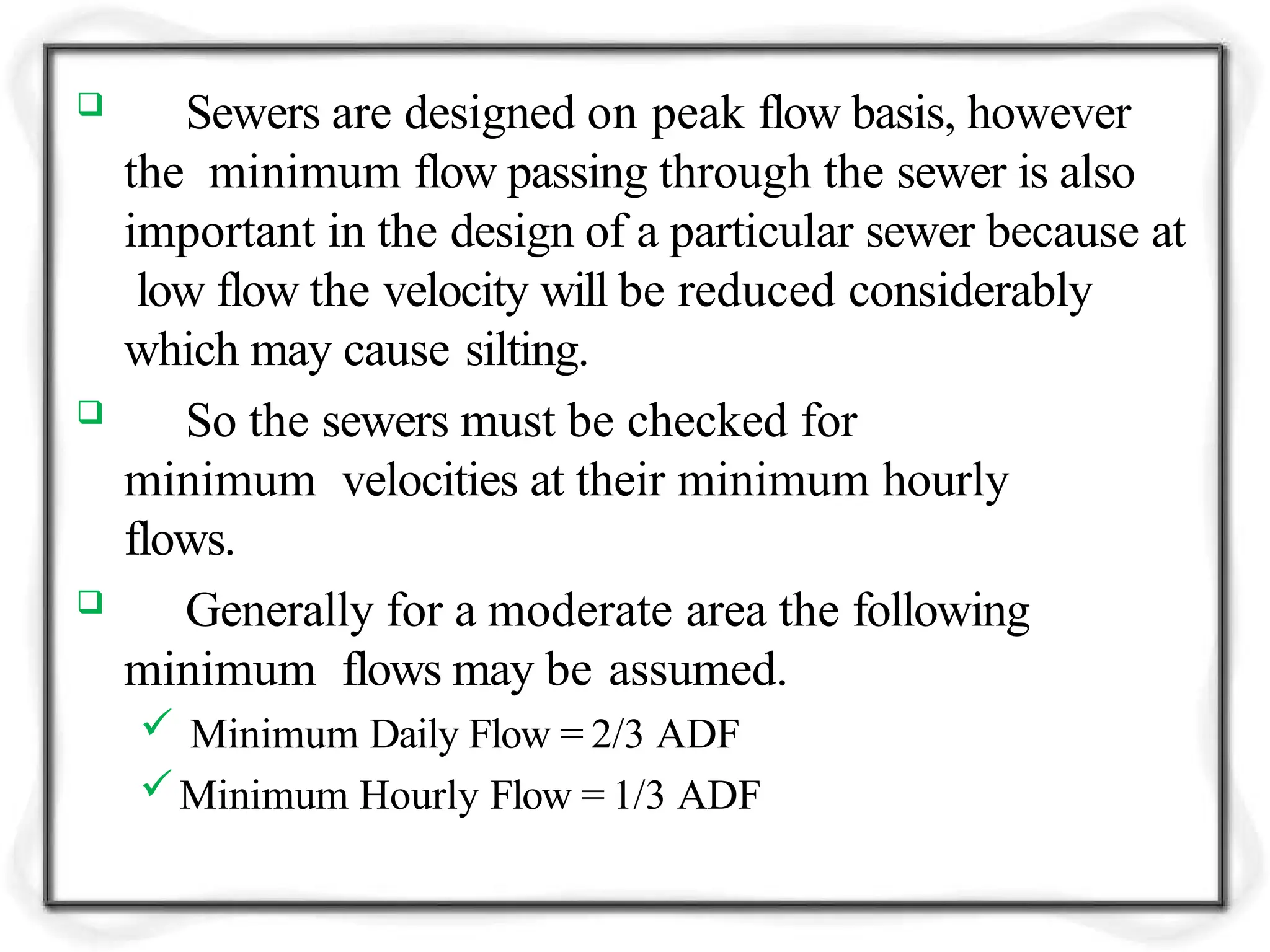
Sewers aredesigned on peak flow basis, however
the minimum flow passing through the sewer is also
important in the design of a particular sewer because at
low flow the velocity will be reduced considerably
which may cause silting.
So the sewers must be checked for
minimum velocities at their minimum hourly
flows.
Generally for a moderate area the following
minimum flows may be assumed.
Minimum Daily Flow = 2/3 ADF
Minimum Hourly Flow = 1/3 ADF
46.
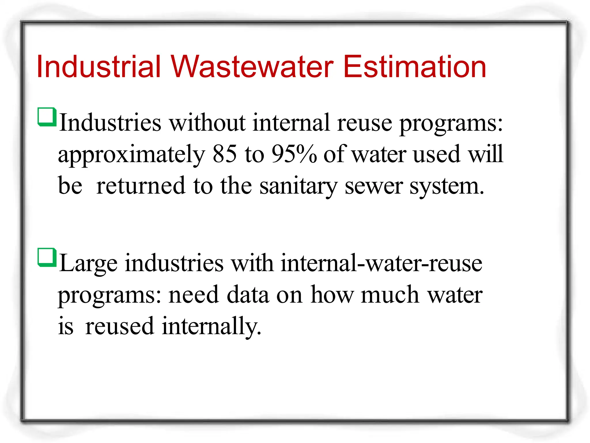
Industrial Wastewater Estimation
Industrieswithout internal reuse programs:
approximately 85 to 95% of water used will
be returned to the sanitary sewer system.
Large industries with internal-water-reuse
programs: need data on how much water
is reused internally.
47.
How is thewastewater going to be
removed and treated?
48.
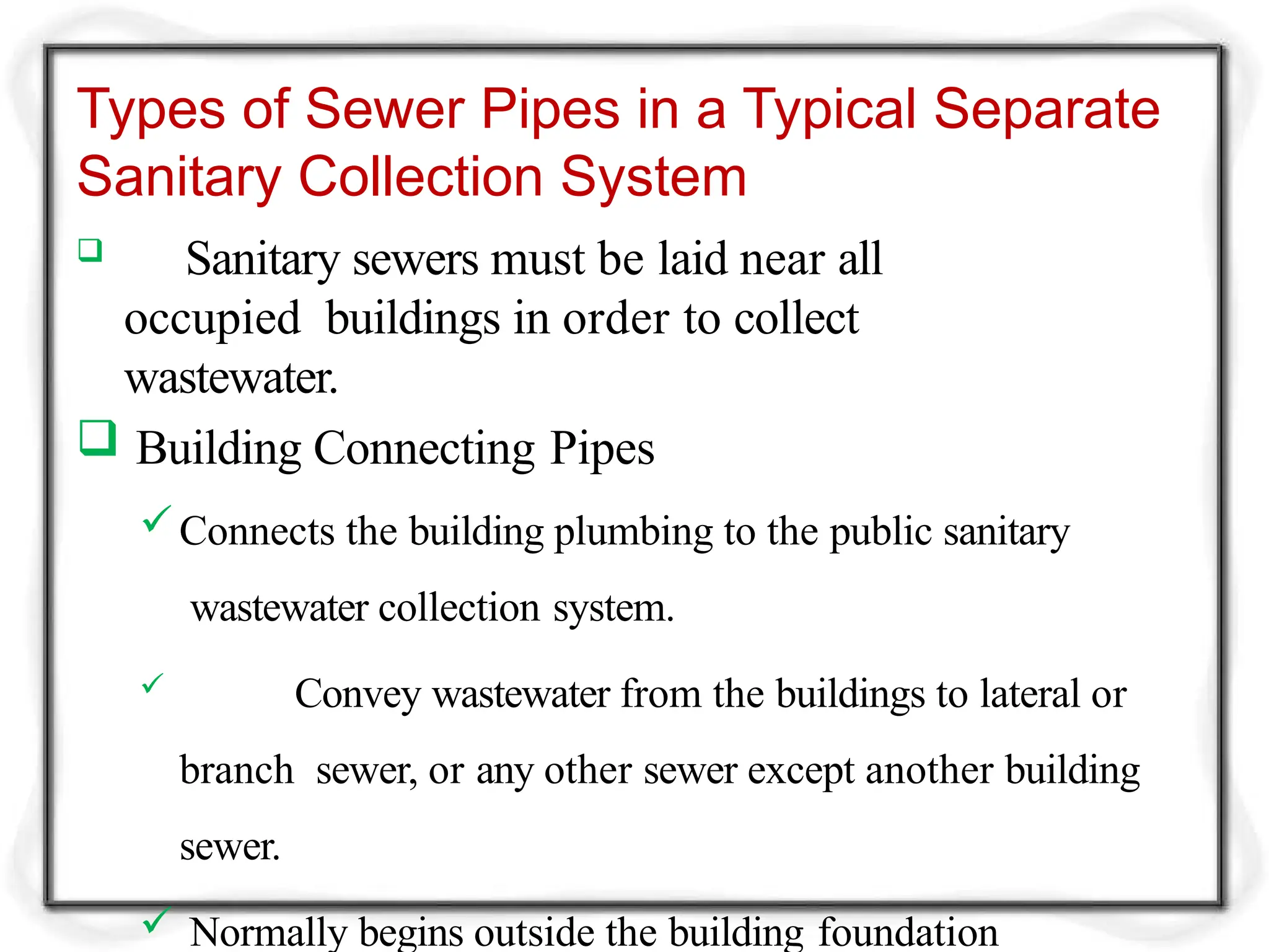
Types of SewerPipes in a Typical Separate
Sanitary Collection System
Sanitary sewers must be laid near all
occupied buildings in order to collect
wastewater.
Building Connecting Pipes
Connects the building plumbing to the public sanitary
wastewater collection system.
Convey wastewater from the buildings to lateral or
branch sewer, or any other sewer except another building
sewer.
Normally begins outside the building foundation
49.
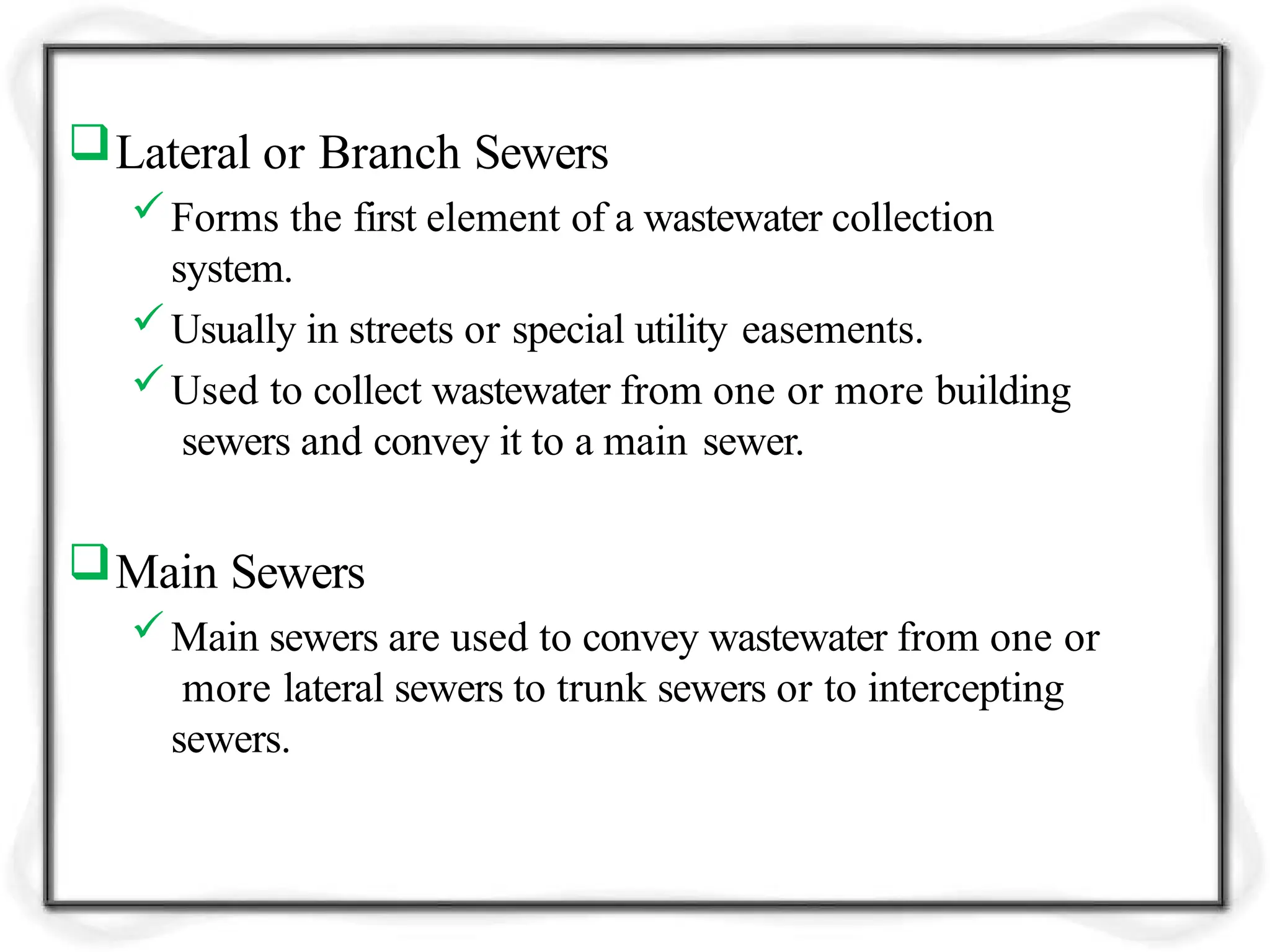
Lateral or BranchSewers
Forms the first element of a wastewater collection
system.
Usually in streets or special utility easements.
Used to collect wastewater from one or more building
sewers and convey it to a main sewer.
Main Sewers
Main sewers are used to convey wastewater from one or
more lateral sewers to trunk sewers or to intercepting
sewers.
50.
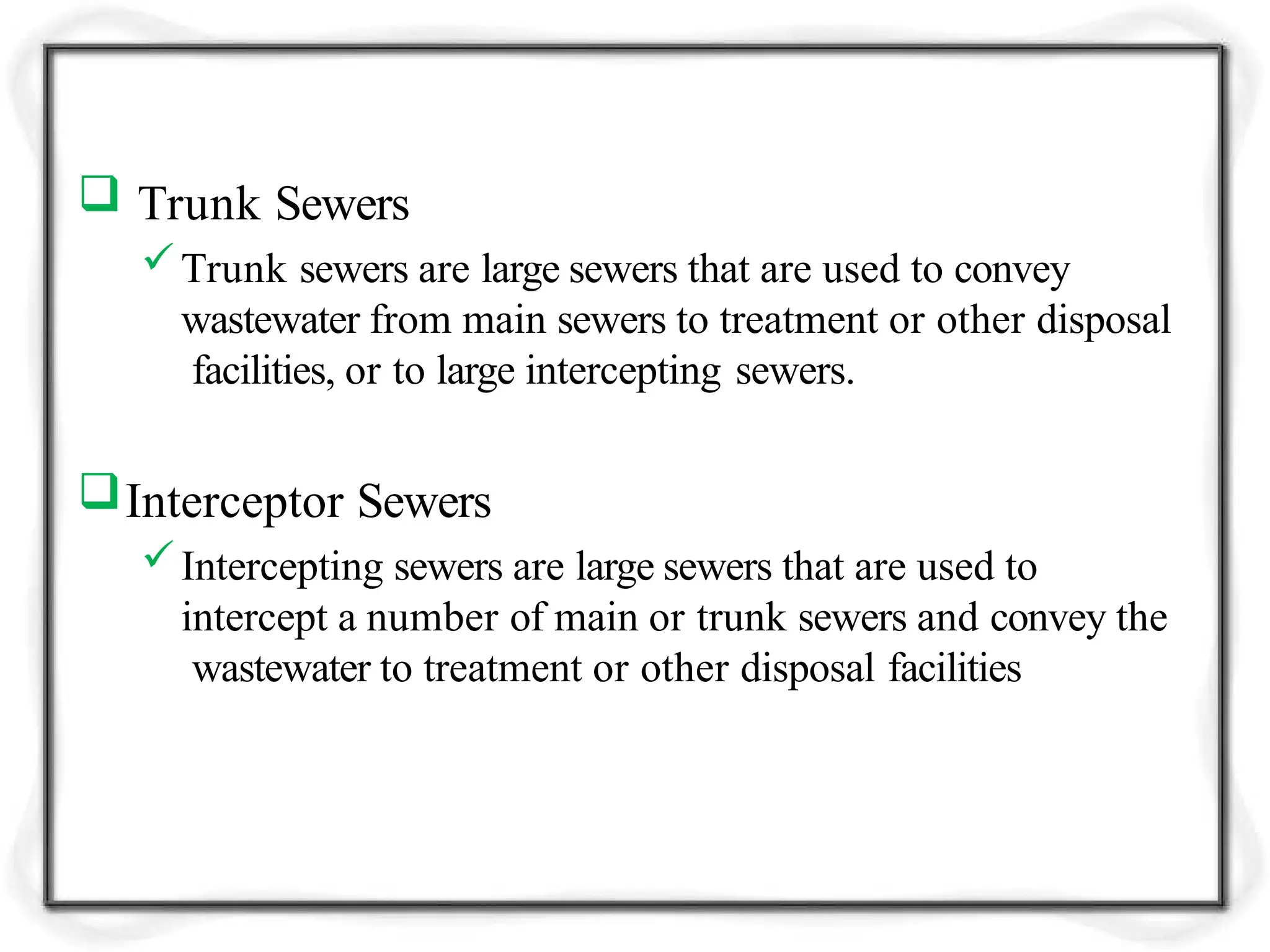
Trunk Sewers
Trunksewers are large sewers that are used to convey
wastewater from main sewers to treatment or other disposal
facilities, or to large intercepting sewers.
Interceptor Sewers
Intercepting sewers are large sewers that are used to
intercept a number of main or trunk sewers and convey the
wastewater to treatment or other disposal facilities
51.
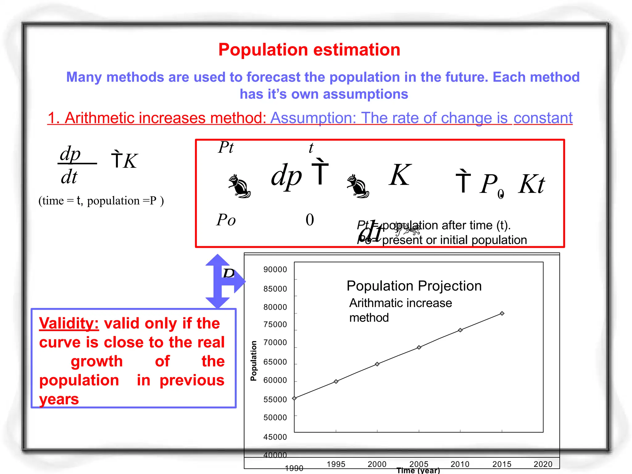
Population estimation
Many methodsare used to forecast the population in the future. Each method
has it’s own assumptions
1. Arithmetic increases method: Assumption: The rate of change is constant
K
dt
dp
(time = t, population =P )
Po 0
Pt t
dp K
dt
Pt
P0 Kt
Pt = population after time (t).
Po= present or initial population
Population Projection
Arithmatic increase
method
90000
85000
80000
75000
70000
65000
60000
55000
50000
45000
40000
1990
1995 2000 2005 2010 2015 2020
Time (year)
Population
Validity: valid only if the
curve is close to the real
growth of the
population in previous
years
52.
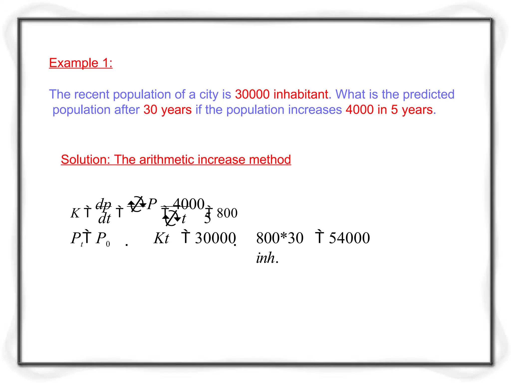
Example 1:
The recentpopulation of a city is 30000 inhabitant. What is the predicted
population after 30 years if the population increases 4000 in 5 years.
Solution: The arithmetic increase method
K
dp
P
4000
800
dt t 5
Pt P0 Kt 30000 800*30 54000
inh.
53.
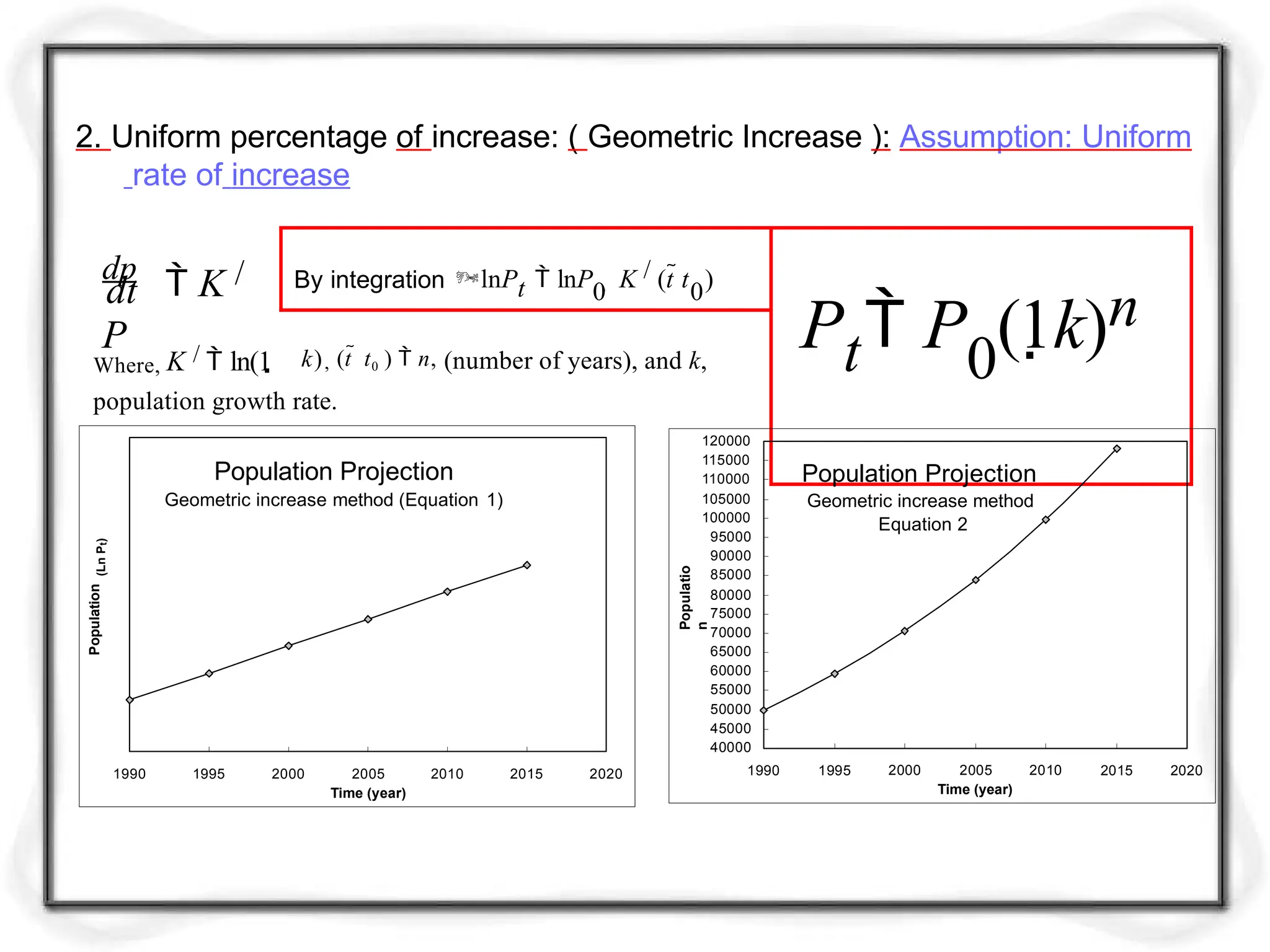
2. Uniform percentageof increase: ( Geometric Increase ): Assumption: Uniform
rate of increase
By integration lnPt lnP0 K / (t t0)
Pt P0
(1k)n
k), (t t0 ) n, (number of years), and k,
dt
dp
K /
P
Where, K / ln(1
population growth rate.
Population Projection
Geometric increase method
Equation 2
120000
115000
110000
105000
100000
95000
90000
85000
80000
75000
70000
65000
60000
55000
50000
45000
40000
1990 1995 2015 2020
2000 2005 2010
Time (year)
Populatio
n
Population Projection
Geometric increase method (Equation 1)
1990 1995 2000 2010 2015 2020
2005
Time (year)
Population
(Ln
P
t
)
54.
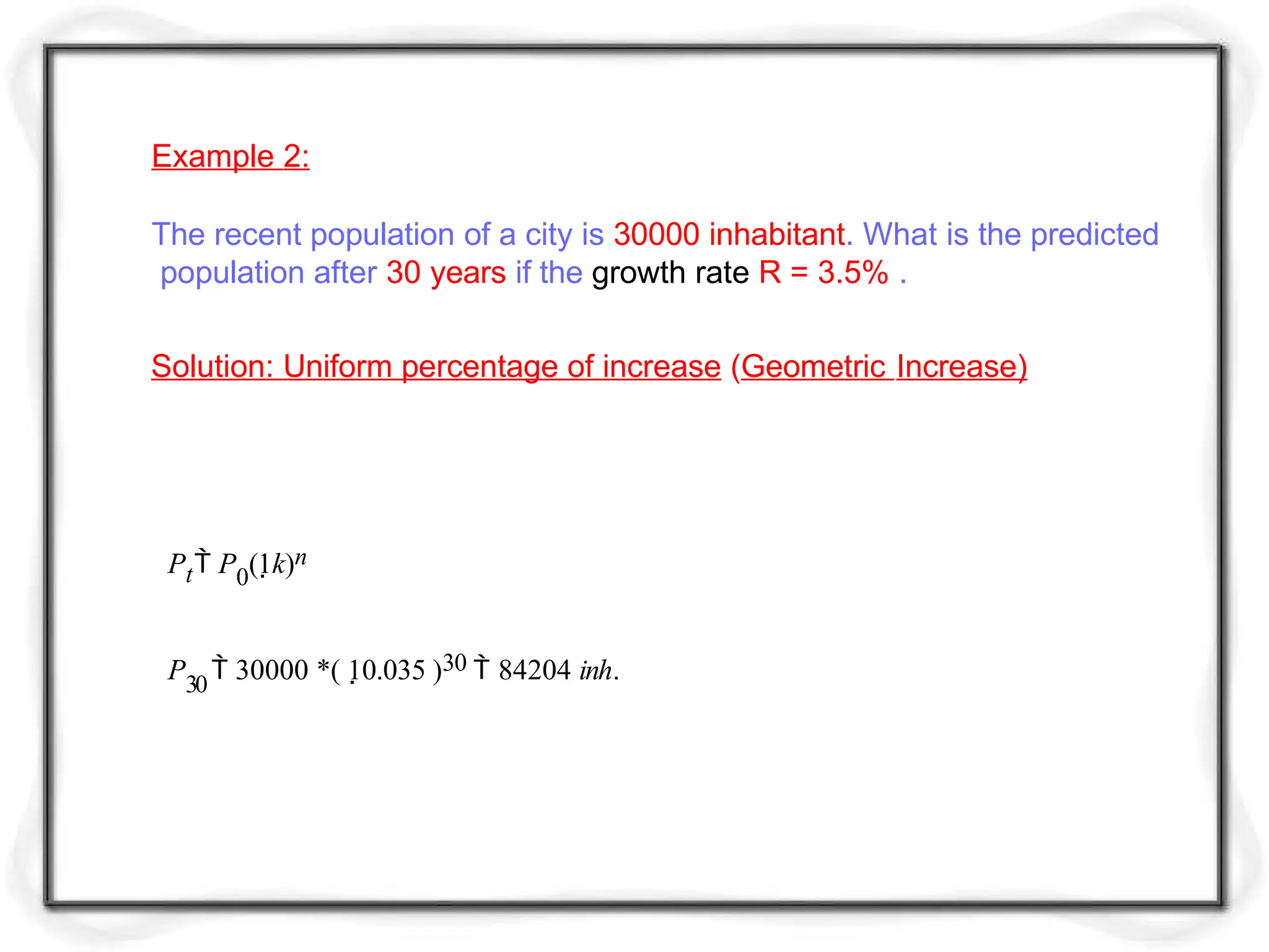
Example 2:
The recentpopulation of a city is 30000 inhabitant. What is the predicted
population after 30 years if the growth rate R = 3.5% .
Pt P0(1k)n
P30
30000 *( 10.035 )30 84204 inh.
Solution: Uniform percentage of increase (Geometric Increase)


![Wondershare Filmora 15.0.11 Crack for Mac Key Full Download [Latest] pptx](https://cdn.slidesharecdn.com/ss_thumbnails/software-251207184836-1d16ba16-thumbnail.jpg?width=640&height=640&fit=bounds)
![CleanMyMac X v5.2.8 Crack for MacOS Full Version [Latest] pptx](https://cdn.slidesharecdn.com/ss_thumbnails/softwareoverview-251207194121-a81f0142-thumbnail.jpg?width=640&height=640&fit=bounds)
![Moho Pro 14.4 Crack for MacOS Works Until 2050 [Latest] pptx](https://cdn.slidesharecdn.com/ss_thumbnails/softwareoverview-251207192639-797289c4-thumbnail.jpg?width=640&height=640&fit=bounds)


![PowerISO 9.2 Mac Crack + Serial Key Free Download 2026 [Latest] Software.pptx](https://cdn.slidesharecdn.com/ss_thumbnails/software-251207185653-5d5700e6-thumbnail.jpg?width=640&height=640&fit=bounds)


![WinRAR Crack 7.13 Final Mac Keygen 2026 Download [Latest] Software.pptx](https://cdn.slidesharecdn.com/ss_thumbnails/software-251207185858-eb450678-thumbnail.jpg?width=640&height=640&fit=bounds)


