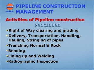
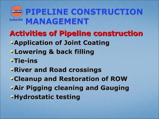
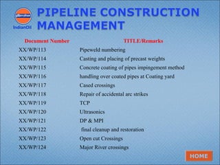
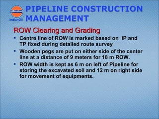
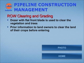
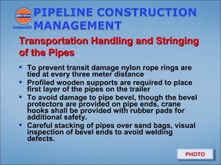
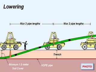
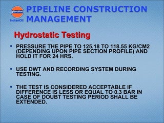
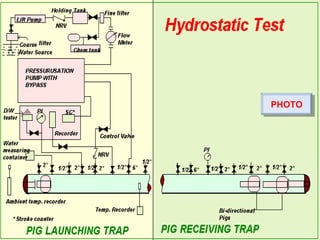
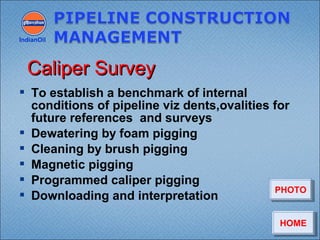
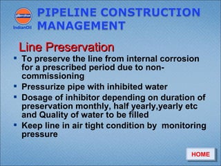
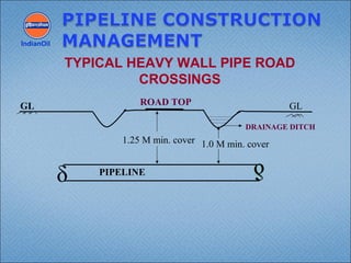
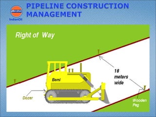
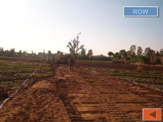
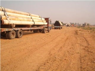
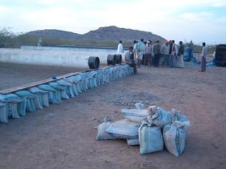
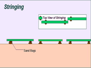
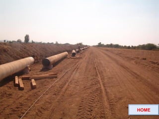
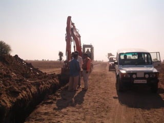
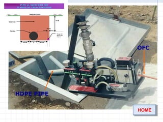
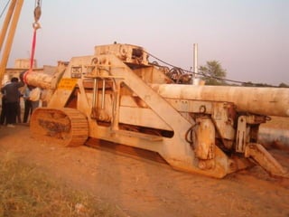
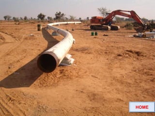
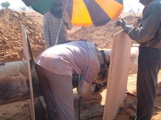
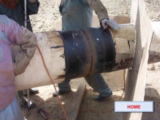
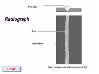
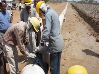
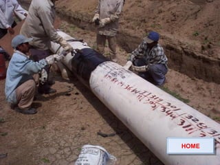
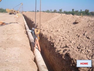
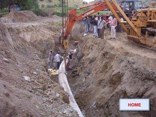
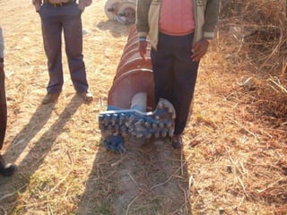
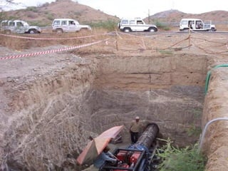
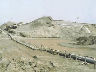
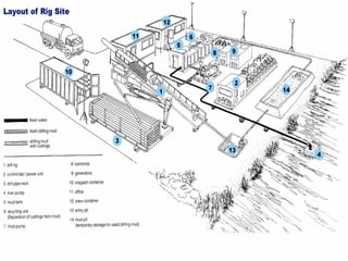
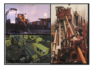
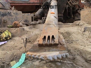
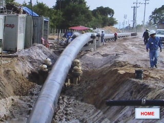
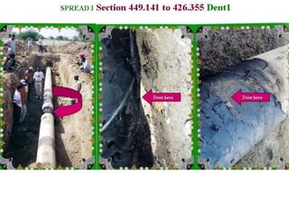
The document describes the procedures for pipeline construction. It involves activities like right of way clearing, trenching, pipe handling, stringing, bending, welding, coating of joints, lowering the pipeline into the trench, backfilling, and hydrotesting. Standard codes and quality checks are specified for each activity to ensure the pipeline is constructed safely and properly.
Ever imagined those how cross-country pipelines where built. The stages of the construction of a pipeline can be likened to a moving assembly line. A large project typically is broken into manageable lengths called “work-spreads,” which utilizes highly specialized and qualified teams. Each spread is composed of various crews, each with its own roles. As one crew completes its work, the next crew moves into position to complete its piece of the construction process. This presentation highlights the key stages of onshore pipeline construction.
A step by step visual guide of a typical cross-country pipeline construction. Useful for a beginner project team to get acquainted with pipeline laying stages.
Presentation on steel, fabrication & erection Munger Ganga BridgeAshish Kumar Yadav
Presentation on Steel Fabrication work and Erection of girder by Cantilever erection method.
One of the largest bridge in India (Bridge Length 3.690 Km)
Similar Bridge 1. Patna- Sonpur (Digha Bridge) across the river Ganga, Bihar
2. Bogibeel across river Brahmaputra in Assam
Oil & Gas Plant Construction, Project Execution PlanDavid H Moloney
Details of how a Gas & Oil Plant is constructed, and how the progress, safety and quality is monitored and controlled. Also the measures to ensure that the site is environmentally friendly.
Quality Control & Quality Assurance of MS pipelineIEI GSC
This presentation re. QC & QA of M S pipelines was made at Gujarat State Centre of the Institution of Engineers (India) at Ahmedabad by Er. Manoj Raghavan of SGS (India) Ltd.
Quality aspects in Cross Country Pipeline constructionSuresh Zanwar
Quality aspects in Cross Country Pipeline construction
Alignment of Pipeline & precautions
Soil erosion in hilly areas & precaution in ROU grading
How pipelines get laid at lower cover & precautions in trenching
Where line pipe string is important and control needed
How to control failure of welding joints
What affects in field coating joint
Pipeline lowering & stress on pipeline – Best laid Pipeline experience
How backfilling makes difference in Pipeline corrosion
How pipeline get exposed on river banks & precaution in river crossing
Safety aspects in Pipeline construction
Why casing & carrier pipe gets shorted
How to make river bank protection
Where cathodic protection fails
Piping Training course-How to be an Expert in Pipe & Fittings for Oil & Gas c...Varun Patel
Course Description
Piping a must know skill to work in Oil & Gas and similar Process Industries.
Oil and Gas industry is become a very competitive in the current time. Getting right mentor and right exposer within industry is difficult. With limited training budget spent by company on employee training, it is difficult to acquire the knowledge to success.
Knowing cross-functional skill give you an edge over others in your career success.
This course design based on years of field experience to ensure student will comprehend technical details easily and enjoy overall journey.
Learn in detail every aspect of Pipe & Pipe Fittings used in process industry
•Different types of Pipe, Pipe fittings (Elbow, Tee, reducers, Caps etc.), Flanges, Gaskets, Branch Connection, Bolting materials
•Materials (Metal-Carbon Steel, Stainless Steel, Alloy Steel etc. Non-Metal- PVC/VCM, HDPE, GRE-GRP etc.)
•Manufacturing methods
•Heat treatment requirements
•Inspection and Testing requirements (Non Destructive Testing, Mechanical & Chemical testing)
•Dimensions & Markings requirements
•Code & Standard used in piping
Content and Overview
With 2 hours of content including 30 lectures & 8 Quizzes, this course cover every aspect of Pipe, Pipe fittings, flanges, gaskets, branch connections and bolting material used in Process Piping.
This Course is divided in three parts.
1st part of the course covers fundamental of process industries. In this Part, you will learn about fundamental process piping. You will also learn about Code, Standard & Specification used in process industries.
2nd part cover various types of material used in process industries. In this part, you will learn about Metallic and Non-Metallic material used to manufacture pipe and other piping components.
3rd parts covers in detail about pipe and piping components used in Process piping. In this part we will learn about Industry terminology of Piping components, types of industrial material grade used in manufacturing and entire manufacturing process of these components. You will learn about different manufacturing methods, Heat treatment requirements, Destructive and Non-destructive testing, Visual & Dimensional inspection and Product marking requirements.
Upon completion, you will be able to use this knowledge direct on your Job and you can easily answer any interview question on pipe & fittings.
Valve and instrumentation calibration and maintenance will assures the accuracy of your industrial instrumentation and valves in accordance with relevant standards
Construction sequence for metro Project (Elevated and Underground) and Time c...Akhilesh Shukla
Construction sequence for metro Project (Elevated and Underground) and Time cycle of the metro construction activity . For more details u can contact me on my mail id -shuklaakhilesh08@gmail.com
This presentation will cover pipe support design, 3D modeling, Finite Element Analysis, special stress and thermal cases, along with the unique cases that brought on new pipe support designs. Increase your understanding of the value-added services that are offered by PT&P.
This Presentation is about the basic fundamentals one needs to know to begin Piping Engineering. All the basic formulas and questions that are usually asked in interviews are answered in this presentation. Feel free to ask any doubts in the comments and iI may try my best to answer them for you.
I have over 11 years of work experience as QA/QC Inspector in Oil and Gas fields both offshore and onshore Construction and installations. focus on PQT/PQR, WQT, NDT, Destructive testing, Inspections of welding and Filed joint coating of Subsea Pipelines, Risers, Tie‐in spools, lateral joints, Jackets, Topside, and Pile pipes. Installation inspection of Pile driving, SPM, PLEMs, I&J tubes, Jackets & top sides.
Epc project interdepency and Work Flow- promoignitetribes
Engineering, Procurement and Construction are highly correlated and set precedence against each other. They are very interdependent and these dependencies become increasingly critical as the phases are overlapped. In this module we share the interdependence of Engineering - Procurement and the influence in Construction. Here we touch a bit on work front monitoring and work face planning.
Within industry, piping is a system of pipes used to convey fluids (liquids and gases) from one location to another. The engineering discipline of piping design studies the efficient transport of fluid
Industrial process piping (and accompanying in-line components) can be manufactured from wood, fiberglass, glass, steel, aluminum, plastic, copper, and concrete. The in-line components, known as fittings, valves, and other devices, typically sense and control the pressure, flow rate and temperature of the transmitted fluid, and usually are included in the field of Piping Design (or Piping Engineering). Piping systems are documented in piping and instrumentation diagrams (P&IDs). If necessary, pipes can be cleaned by the tube cleaning process.
"Piping" sometimes refers to Piping Design, the detailed specification of the physical piping layout within a process plant or commercial building. In earlier days, this was sometimes called Drafting, Technical drawing, Engineering Drawing, and Design but is today commonly performed by Designers who have learned to use automated Computer Aided Drawing / Computer Aided Design (CAD) software
Engineers have introduced devices, known as PIGs, that are sent through the pipelines to perform inspections as well as clean the inside of the pipe. What are the advantages of these modern technologies to pipeline inspection?
How are companies in North America conducting In Line Inspection of pipelines? Discover the costs, common causes, piggability statistics, total number of pigging runs and other useful info.
CD March 2015 - Bentley presentation about current BIM thinkingComit Projects Ltd
Presentation delivered by Iain Miskimmin (COMIT chairman for Technology) about the current industry thinking with regards to BIM. Presented at the COMIT Community Day on 12th March 2015 in London.
Prism Groups corporate presentation.Prism group has formed after Prism surface coatings acquires a 50 YEAR OLD GERMAN company called OMT technologies.Omt technologies was the one of the leading painting and powder coating plant supplier in Europe, South america and North america.Prism has supplied over 500 coating lines worldwide and is the only company with the largest number of references and industry specific experience.
manufacturing and supplying an incomparable assortment of Timber Cooling Towers, Axial Fan, Flange type Motors, Fan Cylinder, Sprinkler, F C Valve, Yoke Gear side, Fan Coupling, Nozzle, Rubber Bush, Cooling Tower Gear Box, Tower Casing, Sprinkler Pipes, Electric Motors, Perforated Slats, Cooldeck Drift Eliminator and many more.
6th International Conference on Machine Learning & Applications (CMLA 2024)ClaraZara1
6th International Conference on Machine Learning & Applications (CMLA 2024) will provide an excellent international forum for sharing knowledge and results in theory, methodology and applications of on Machine Learning & Applications.
Sachpazis:Terzaghi Bearing Capacity Estimation in simple terms with Calculati...Dr.Costas Sachpazis
Terzaghi's soil bearing capacity theory, developed by Karl Terzaghi, is a fundamental principle in geotechnical engineering used to determine the bearing capacity of shallow foundations. This theory provides a method to calculate the ultimate bearing capacity of soil, which is the maximum load per unit area that the soil can support without undergoing shear failure. The Calculation HTML Code included.
Forklift Classes Overview by Intella PartsIntella Parts
Discover the different forklift classes and their specific applications. Learn how to choose the right forklift for your needs to ensure safety, efficiency, and compliance in your operations.
For more technical information, visit our website https://intellaparts.com
Saudi Arabia stands as a titan in the global energy landscape, renowned for its abundant oil and gas resources. It's the largest exporter of petroleum and holds some of the world's most significant reserves. Let's delve into the top 10 oil and gas projects shaping Saudi Arabia's energy future in 2024.
Student information management system project report ii.pdfKamal Acharya
Our project explains about the student management. This project mainly explains the various actions related to student details. This project shows some ease in adding, editing and deleting the student details. It also provides a less time consuming process for viewing, adding, editing and deleting the marks of the students.
About
Indigenized remote control interface card suitable for MAFI system CCR equipment. Compatible for IDM8000 CCR. Backplane mounted serial and TCP/Ethernet communication module for CCR remote access. IDM 8000 CCR remote control on serial and TCP protocol.
• Remote control: Parallel or serial interface.
• Compatible with MAFI CCR system.
• Compatible with IDM8000 CCR.
• Compatible with Backplane mount serial communication.
• Compatible with commercial and Defence aviation CCR system.
• Remote control system for accessing CCR and allied system over serial or TCP.
• Indigenized local Support/presence in India.
• Easy in configuration using DIP switches.
Technical Specifications
Indigenized remote control interface card suitable for MAFI system CCR equipment. Compatible for IDM8000 CCR. Backplane mounted serial and TCP/Ethernet communication module for CCR remote access. IDM 8000 CCR remote control on serial and TCP protocol.
Key Features
Indigenized remote control interface card suitable for MAFI system CCR equipment. Compatible for IDM8000 CCR. Backplane mounted serial and TCP/Ethernet communication module for CCR remote access. IDM 8000 CCR remote control on serial and TCP protocol.
• Remote control: Parallel or serial interface
• Compatible with MAFI CCR system
• Copatiable with IDM8000 CCR
• Compatible with Backplane mount serial communication.
• Compatible with commercial and Defence aviation CCR system.
• Remote control system for accessing CCR and allied system over serial or TCP.
• Indigenized local Support/presence in India.
Application
• Remote control: Parallel or serial interface.
• Compatible with MAFI CCR system.
• Compatible with IDM8000 CCR.
• Compatible with Backplane mount serial communication.
• Compatible with commercial and Defence aviation CCR system.
• Remote control system for accessing CCR and allied system over serial or TCP.
• Indigenized local Support/presence in India.
• Easy in configuration using DIP switches.
Hybrid optimization of pumped hydro system and solar- Engr. Abdul-Azeez.pdffxintegritypublishin
Advancements in technology unveil a myriad of electrical and electronic breakthroughs geared towards efficiently harnessing limited resources to meet human energy demands. The optimization of hybrid solar PV panels and pumped hydro energy supply systems plays a pivotal role in utilizing natural resources effectively. This initiative not only benefits humanity but also fosters environmental sustainability. The study investigated the design optimization of these hybrid systems, focusing on understanding solar radiation patterns, identifying geographical influences on solar radiation, formulating a mathematical model for system optimization, and determining the optimal configuration of PV panels and pumped hydro storage. Through a comparative analysis approach and eight weeks of data collection, the study addressed key research questions related to solar radiation patterns and optimal system design. The findings highlighted regions with heightened solar radiation levels, showcasing substantial potential for power generation and emphasizing the system's efficiency. Optimizing system design significantly boosted power generation, promoted renewable energy utilization, and enhanced energy storage capacity. The study underscored the benefits of optimizing hybrid solar PV panels and pumped hydro energy supply systems for sustainable energy usage. Optimizing the design of solar PV panels and pumped hydro energy supply systems as examined across diverse climatic conditions in a developing country, not only enhances power generation but also improves the integration of renewable energy sources and boosts energy storage capacities, particularly beneficial for less economically prosperous regions. Additionally, the study provides valuable insights for advancing energy research in economically viable areas. Recommendations included conducting site-specific assessments, utilizing advanced modeling tools, implementing regular maintenance protocols, and enhancing communication among system components.
Welcome to WIPAC Monthly the magazine brought to you by the LinkedIn Group Water Industry Process Automation & Control.
In this month's edition, along with this month's industry news to celebrate the 13 years since the group was created we have articles including
A case study of the used of Advanced Process Control at the Wastewater Treatment works at Lleida in Spain
A look back on an article on smart wastewater networks in order to see how the industry has measured up in the interim around the adoption of Digital Transformation in the Water Industry.
Using recycled concrete aggregates (RCA) for pavements is crucial to achieving sustainability. Implementing RCA for new pavement can minimize carbon footprint, conserve natural resources, reduce harmful emissions, and lower life cycle costs. Compared to natural aggregate (NA), RCA pavement has fewer comprehensive studies and sustainability assessments.
2. Activities of Pipeline constructionActivities of Pipeline construction
PROCEDUREPROCEDURE
Right of Way clearing and gradingRight of Way clearing and grading
Delivery, Transportation, Handling,Delivery, Transportation, Handling,
Hauling, Stringing of pipesHauling, Stringing of pipes
Trenching Normal & RockTrenching Normal & Rock
BendingBending
Lining up and WeldingLining up and Welding
Radiographic InspectionRadiographic Inspection
IndianOil
3. Activities of Pipeline constructionActivities of Pipeline construction
Application of Joint CoatingApplication of Joint Coating
Lowering & back fillingLowering & back filling
Tie-insTie-ins
River and Road crossingsRiver and Road crossings
Cleanup and Restoration of ROWCleanup and Restoration of ROW
Air Pigging cleaning and GaugingAir Pigging cleaning and Gauging
Hydrostatic testingHydrostatic testing
IndianOil
4. Activities of Pipeline constructionActivities of Pipeline construction
De watering cleaning and SwabbingDe watering cleaning and Swabbing
Golden Tie insGolden Tie ins
Valve installationValve installation
Caliper survey and dent repairsCaliper survey and dent repairs
Line PreservationLine Preservation
IndianOil
5. IndianOil
WORK PROCEDURE
Purpose:
The purpose of work procedure is to
stipulate the method that shall be used for
a particular activity covering even minute
steps in details.
The work procedure is to be prepared by agency
responsible for execution of work.
The work procedure is examined criticaly and
approved by owner/owner representative.
No deviation from work procedure is accepted.
6. IndianOil
NEED FOR WORK PROCEDURE
It helps:
1.In clearly defining the procedure to be
adopted in execution of activity.
2.In establishing QAP a tool for inspection.
3.In developing records for future
reference.
4.In case of any dispute arising at later
stage.
8. IndianOil
Document Number TITLE/Remarks
XX/WP/100 Survey,Clearing & Grade
XX/WP/101 Trench
XX/WP/102 Blasting
XX/WP/103 Pipe Handling And Stringing
XX/WP/104 Bending
XX/WP/105 Concrete coating by casting procedure
XX/WP/106 Tie-in
XX/WP/107 NDT Procedure for Mainline Welding
XX/WP/108 Applications of Heat shrinkable sleeves
XX/WP/109 Lowering in and rock shield applications
XX/WP/110 Backfill
XX/WP/111 Cathodic protection installation
XX/WP/112 Pre testing of Pipeline crossings
9. IndianOil
Document Number TITLE/Remarks
XX/WP/113 Pipeweld numbering
XX/WP/114 Casting and placing of precast weights
XX/WP/115 Concrete coating of pipes impingement method
XX/WP/116 handling over coated pipes at Coating yard
XX/WP/117 Cased crossings
XX/WP/118 Repair of accidental arc strikes
XX/WP/119 TCP
XX/WP/120 Ultrasonics
XX/WP/121 DP & MPI
XX/WP/122 final cleanup and restoration
XX/WP/123 Open cut Crossings
XX/WP/124 Major River crossings
HOME
10. Centre line of ROW is marked based on IP and
TP fixed during detailed route survey
Wooden pegs are put on either side of the center
line at a distance of 9 meters for 18 m ROW.
ROW width is kept as 6 m on left of Pipeline for
storing the excavated soil and 12 m on right side
for movement of equipments.
IndianOil
ROW Clearing and GradingROW Clearing and Grading
11. Dozer with flat front blade is used to clear the
vegetation and trees
Prior information to land owners to clear the land
of their crops before entering
IndianOil
ROW Clearing and GradingROW Clearing and Grading
HOME
PHOTO
12. To prevent transit damage nylon rope rings are
tied at every three meter distance
Profiled wooden supports are required to place
first layer of the pipes on the trailer
To avoid damage to pipe bevel, though the bevel
protectors are provided on pipe ends, crane
hooks shall be provided with rubber pads for
additional safety.
Careful stacking of pipes over sand bags, visual
inspection of bevel ends to avoid welding
defects.
IndianOil
Transportation Handling and StringingTransportation Handling and Stringing
of the Pipesof the Pipes
PHOTOPHOTO
13. In cultivable land, to strip top soil (30 cm depth)
& store separately along ROW for replacement
on top of backfilled ditch.
Provide suitable crossings across open ROW
for land owners/ public.
Width of trench : Pipe OD + 300 mm.
Depth of trench to be measured from original
ground/ graded surface/ top of road/ bottom of
rail, whichever is lower.
IndianOil
TRENCHINGTRENCHING
14. Provide 300 mm additional cover where pipeline
is within 15 m of private dwelling, industrial
buildings or public places.
Provide temp. diversions/ bridges at road
crossings to allow passage of normal traffic
with min. inconvenience.
Provide warning/ traffic signs, lights,
barricades, fencing, watchmen as required by
local authorities.
Provide extra depth to fit min. radius of bend at
crossings.
IndianOil
TRENCHINGTRENCHING
15. Sl.Sl.
No.No.
LocationLocation Min. CoverMin. Cover
(m)(m)
11 Industrial, Commercial, Residential Areas (NormalIndustrial, Commercial, Residential Areas (Normal
Terrain)Terrain)
1.251.25
22 Uncased/ Cased Road CrossingsUncased/ Cased Road Crossings
& Cart-Track Crossings& Cart-Track Crossings
1.251.25
33 Railway CrossingsRailway Crossings 1.701.70
44 Normal Terrain / Drainage ditches at Railways,Normal Terrain / Drainage ditches at Railways,
Highways etc.Highways etc.
1.201.20
55 Minor Water Course CrossingsMinor Water Course Crossings 1.501.50
66 Marshy Areas/ Water reservoir Areas/ PondsMarshy Areas/ Water reservoir Areas/ Ponds 1.501.50
77 Submerged River CrossingsSubmerged River Crossings 2.502.50
88 Rocky AreasRocky Areas 1.001.00
17. Cold field bends for change of vertical & horizontal
alignment by using bending machine & mandrel.
Bends to be made without causing wrinkles,
buckles, stretching & damage to pipe coating.
Bending procedure to be established including step
length & max. degree per pull per foot (0.9550 for
18” OD pipes).
Over bends to be made to clear high points of the
trench bottom.
IndianOil
BENDINGBENDING
18. Sag bends to fit the bottom of the trench.
Side bends to leave min. clearance to trench wall.
Radius of curvature > 40 D upto 18” OD & > 60 D for
above 18” OD pipes.
End of bend should not be closer than 2 m from
girth weld or pipe end.
Bends to be installed by positioning longitudinal
welds in upper quadrant.
IndianOil
BENDINGBENDING
19. Ovality of bent pipe < 2.5 % of nominal dia. at any
point; to be checked by passing a gauge consisting
of two discs of 95% nominal pipe internal dia.
To layout pipes in such a way that Nos. of pieces cut
off less than 2 m are held min.
No Mitre bends are permitted.
Hot pulled bends may be used in unavoidable
circumstances.
IndianOil
BENDINGBENDING
PHOTOPHOTO
21. FOLLOWING STANDARDS/CODES ARE
REFFERED IN INSPECTION & TESTING OF
WELD.
API 1104, Welding of pipelines and related
facilities.
ASME Sec IX, Boiler & Pressure vessel Code.
IndianOil
STANDARDS/CODESSTANDARDS/CODES
23. A) Tensile strength test
B) Nick break test
C) Root, face and side bend test
IndianOil
Destructive TestDestructive Test
24. Scope of work includes 100% Radiographic
inspection of all joints for the initial 1 Km of
the pipeline in each spread. For balance
portion of the pipeline ,20% of all joints shall
be radio-graphically inspected except for
specific crossings and tie-ins which need
100% radio-graphic inspection
IndianOil
RadiographyRadiography
26. COATING CLEARANCE IS AVAILABLE FROM
RADIOGRAPHY CREW.
HUMIDITY <85%, IF BETWEEN 75% TO 85%
PREHEAT BEFORE BLASTING.
CLEANING OF JOINT AREA AND ADJACENT
COATING DONE UPTO 100MM ON CTE COATING
ON BOTH PIPES
CHAMPER THE PIPE COATING TO AN ANGLE<30
PREHEAT THE WELDED JOINT AREA TO 60-80 C
IndianOil
JOINT COATINGJOINT COATING
27. SANDBLASTING IS DONE UPTO 100 MM ON CTE
COATING ON BOTH PIPES
ENTIRE SAND BLAST SURFACE IS FREE FROM
MOISTURE.
THE ROUGHNESS OF SAND BLASTED SURFACES
IS BETWEEN 50-70 MICRON AS MEASURED BY
PRESS-O-FILM/ELCOMETER.
PART A(60+10ml)PRIMER & PART B(30+10ml)
EPOXY IS MIXED FOR MIN 30 SEC
PREHEATING OF PIPE TO A TEMPERATURE OF 60-
80o
C DONE.
IndianOil
JOINT COATINGJOINT COATING
28. THE OVERLAP POSITION OF THE SLEEVE IS AT 2
OR 10 ‘O’ CLOCK.
WET FILM THICKNESS OF PRIMER IS BETWEEN 50-
70 MICRONS.
SIDE OF OVERLAP PORTION HEATED & PRESSED
WITH SILICON ROLLERS.
THE CLOSURE PATCH IS HEATED, PRESSED &
SEALED ON THE SLEEVE.
DIRECTION OF FLAME IS CIRCULAR & FROM ONE
END TO OTHER END.
THE SLEEVE IS COMPLETELY SHRUNK AND
CONFORMS TO PIPE
IndianOil
JOINT COATINGJOINT COATING
29. SLEEVE IS FREE FROM WRINKLES, COLD SPOTS,
ENTRAPPED AIR IS EXPELLED BY HEATING &
PRESSING WITH ROLLER OR BY HAND.
THICKNES OF SLEEVE ON WELD SEEM IS MIN
1.7MM AND ON PARENT METAL IS MIN 2MM.
PEEL TEST DONE ONE IN EVERY 100 JOINTS OR
DAY’S PRODUCTION WHICHEVER IS LOWER ON
SUBSEQUENT MORNING.
IndianOil
JOINT COATINGJOINT COATING
30. PEEL TEST PROCEDURE
PEEL SIZED 1” BY 8” PEEL CUT UPTO BARE PIPE
ANY LOCATION- AT WELDED SEAM, ON PIPE AND
ON CTE COATING
FAILS IF PEEL OF FORCE IS LESS AT OBSERVED
TEMP. OR ADHESIVE LAYER OF SLEEVE IS
PEELED OFF FROM PIPE.
PEEL TESTED PORTION IS REPAIRED.
IndianOil
JOINT COATINGJOINT COATING
PHOTOPHOTO
31. Before lowering of pipeline in the trench,
To clear the trench of all debris, stones, pipe
cut pieces, welding rods, hard clods, skids etc.
before lowering of pipeline.
To drain out water from the trench (if any) to
avoid floatation.
To carry out complete check by full circle
holiday detector.
IndianOil
PIPELINE LOWERING IN TRENCHPIPELINE LOWERING IN TRENCH
32. Before lowering of pipeline in the trench,
To repair all coating damages.
To provide sand padding (150 mm thick) free
from gravel/ pebbles in rocky areas.
Pipeline to be lifted & laid by using non-
abrasive material (Teflon) coated hooks.
IndianOil
PIPELINE LOWERING IN TRENCHPIPELINE LOWERING IN TRENCH
33. Before lowering of pipeline in the trench,
No sling to be put around field joint coating.
Adequate Nos. of side booms to be used for holding the
pipeline in gentle S-curve maintaining elastic bend
radius.
Pipeline not to be laid in tension. Trench to be rectified
(if required) so that the pipeline fits the excavation and
rests on the trench bed.
To avoid movement of pipeline in the trench.
IndianOil
PIPELINE LOWERING IN TRENCHPIPELINE LOWERING IN TRENCH
34. BACKFILLING OF PREVIOUS SECTION HAS
BEEN COMPLETED.
LOWERING CLEARANCE FROM JOINT COATING
SITE IS AVAILABLE.
RADIOGRAPHY CLEARANCE FOR LEFT OUT
JOINTS IS AVAILABLE.
COATING CHECKED VISUALLY FOR DEFECTS
AND REPAIRS DONE, IF REQUIRED.
HOLIDAY DONE AT 15 KV
DEPTH AT 4 LOCATIONS IS CHECKED AND
FOUND .1.5 M
IndianOil
PIPELINE LOWERING IN TRENCHPIPELINE LOWERING IN TRENCH
35. WIDTH CHECKED AT BOTTOM OF TRENCH AT 4
LOCATIONS AND FOUND . 1.2 m
TRENCH BOTTOM IS FREE FROM ROCKY
STRATA
SOFT PADDING ON THE BOTTOM OF TRENCH
DONE
NIGHT CAPS ARE PROVIDED ON OPEN ENDS OF
PIPE SECTION.
SLING OF SIDE BOOM IS NOT BE ON FIELD
JOINT COATING.
PIPE IS LOWERED IN THE RIGHT SIDE OF THE
TRENCH.
DISTANCE OF HDPE PIPE FROM MAIN PIPE IS
400MM.
IndianOil
PIPELINE LOWERING IN TRENCHPIPELINE LOWERING IN TRENCH
36. SPIKES PROVIDED AT 10 M INTERVAL ALONG
THE ROUTE OF HDPE PIPE.
SPIKE REMOVED AFTER PADING.
WARNING TAPE IS LAID AT 400 MM ABOVE
HDPE PIPE
IndianOil
PIPELINE LOWERING IN TRENCHPIPELINE LOWERING IN TRENCH
38. The gaps which are left out during mainline
welding due to road/railway crossing,
canal/river crossings etc are connected in
the form of Tie-in joints
IndianOil
Tie- InsTie- Ins
PHOTOPHOTO
39. 1. Cased crossings for Railways & Highways (NH/ SH)
Casing pipe: 24” OD x 0.281” WT API 5L Gr. B
Carrier Pipe: 18” OD x 0.250” WT API 5L X65
2. Uncased crossings (open cut) for minor roads/ cart –
tracks using heavy wall pipe (18” OD x 0.281” WT API
5L X65).
3. Minor water course crossings (open cut) using normal
pipe (18” OD x 0.250” WT API 5L X65)
IndianOil
TYPES OF CROSSINGSTYPES OF CROSSINGS
40. 4. Submerged river crossings (open cut) using heavier
wall pipe (18” OD x 0. 375” WT API 5L X65) with
concrete coating/ HDD XING
5. Crossings for existing underground facilities like
pipelines, cables using normal pipe (18” OD x 0.250”
WT API 5L X65) with min. clearance of 500 mm.
Crossings at Sl. No. 2, 3 & 5 above are part of mainline
item.
Cased and submerged river crossings are separate
items.
IndianOil
TYPES OF CROSSINGSTYPES OF CROSSINGS
41. Execute crossing work as per concerned Statutory Authority
permission conditions.
Highways, main roads, rail roads & their verges and banks of water
courses not to be used for loading, unloading or stacking of
materials or equipment.
Roads or water courses not to be closed or diverted without prior
permission of concerned Statutory Authority.
Before execution of cased and submerged river crossings, detailed
methodology to be submitted by contractor containing:
Time schedule,
Working method,
Equipment to be deployed
Test procedure
Manning
Soil Investigations.
IndianOil
CROSSINGSCROSSINGS
42. To be executed by horizontal boring technique.
Casing pipe to be 6” larger in dia. than carrier
pipe.
Carrier pipes to be 3 LPE coated. No coating of
casing pipes.
Ground water table (if encountered) over length
of boring to be lowered up to at least 0.5 m
below bottom of the pipeline.
IndianOil
CASED CROSSINGSCASED CROSSINGS
43. For boring pits in unstable soils, closed sheet
piling to be used.
Boring/ exit pit bottom to be graded for min. 12
m at the approach to each end of casing.
Backfill in boring/ exit pits to be compacted in
15 cm layers to 90% proctor density by mech.
compactor after dewatering.
IndianOil
CASED CROSSINGSCASED CROSSINGS
44. Dia. of bored hole to be almost same as casing
pipe OD.
Vent pipes to be provided on both ends of
casing in such a way that there is no contact
with carrier pipe.
100% radiographic inspection of weld joints of
carrier pipes.
IndianOil
CASED CROSSINGSCASED CROSSINGS
45. Prior to installation, hydrostatic pre-testing of
the carrier pipeline section to be carried out at a
pressure corresponding to 95% SMYS of pipe
material (120.62 kg/cm2 for SSPL) . Test
pressure to be maintained for min. 4 hrs.
Insulators to be securely fastened to carrier
pipes @ 1 m c/c.
IndianOil
CASED CROSSINGSCASED CROSSINGS
46. At both ends of casing, double set of insulators
to be installed.
Carrier pipe to be pulled/ pushed into casing in
such a way that insulators are not disturbed.
Annular space between casing and carrier
pipes at both ends to be packed tightly with jute
and bitumen before fixing end seals in order to
prevent ingress of moisture/ water.
IndianOil
CASED CROSSINGSCASED CROSSINGS
47. After installation, electrical test to be conducted
to determine resistance between carrier pipe &
casing pipe or carrier pipe & soil, which should
be min. 1 mega ohm.
The earth to be properly compacted up to a
distance of 3 m from end of casing pipe on both
sides to avoid uneven settlement of carrier
pipe.
IndianOil
CASED CROSSINGSCASED CROSSINGS
48. IndianOil
TYPICAL CASED RAILWAYTYPICAL CASED RAILWAY
CROSSINGCROSSING
1.25 m
1.0 m Min.
1.7 m Min.
Vent Pipe
(80mm dia. MS pipe)
18 OD x 0.250” WT API 5L-X65 Grade Carrier Pipe
24 OD x 0..312” WT API 5L Grade B Casing Pipe
HDPE End SealHDPE Insulators
@ 1 m c/c
Boring Pit Exit Pit
1.0 m Min.1.0 m Min.
Railway
0.3 m.
0.5 m
GL
GL
PHOTOPHOTO
49. Clear the site by removing all rubbish,broken
skids, empty canes,pieces of electrodes and other
construction material
Restore ROW to the satisfaction of farmers and
obtain NOC from them
Restore cut roads, canals, river banks etc and
obtain NOC from concerned Government
Department
IndianOil
Clean-Up and RestorationClean-Up and Restoration
PHOTOPHOTO
50. Cleaning with compressed air with the help
of series of brush pigs
Gauge plate of softer metal like Al of 95%
of ID of highest wall thickness pipe is
fastened to pig
Retrieved gauge plate is analyzed and
preserved
IndianOil
Air pigging cleaning and GaugingAir pigging cleaning and Gauging
PIGPIG
52. MECHANICAL CLEARANCE IS AVAILABLE. (Pipe
book completed)
INSTRUMENTS AND EQUIPMENT TO BE USED ARE
WITH VALID CALIBRATION AND OF REQUIRED
RATING.
WATER TESTING CERTIFICATE AND CORROSION
INHIBITOR DOSAGE RECOMMENDATION
AVAILABLE.
IndianOil
Hydrostatic TestingHydrostatic Testing
53. GAUGE PLATE OF 95% ID AND 10 MM THICKNESS
SHALL BE PASSED THROUGH THE SECTION
AFTER CLEANING OF THE PIPE.
GAUGE PLATE WITH < 2 MM SCRATCH ON SIDE
WALL AND WITH NO DENT IS ACCEPTABLE.
CHECKING THE CONDITION AND SEQUENCE OF
PIGS IN THE HYDROSTATIC HEADER.
IndianOil
Hydrostatic TestingHydrostatic Testing
54. ONLY QUALIFIED WELDER IS ALLOWED TO
PERFORM WELDING OF HEADER.
CHECK RATING AND CONDITION OF HEADER
FITTINGS.
USE THE FILLING WATER FROM TESTED
WATER SOURCE ONLY.
FILL 500 MTRS. OF WATER BEFORE FIRST PIG
AND 1000 MTR WATER BETWEEN FIRST AND
SECOND PIG.
FINAL FILLING SHALL BE DONE WITH FILL RATE
OF 2 KM/HRS.
IndianOil
Hydrostatic TestingHydrostatic Testing
55. AFTER RECEIPT OF PIGS AT RECIVER MINIMUM
2 HRS. WATER FLUSHING SHALL BE ENSURED.
TURBINE METER READING RECORDING SHALL
BE PRESERVED.
THERMAL STABILIZATION FOR 24 HRS. SHALL
BE DONE AND SECTION IS SAID TO BE
THERMALLY STABILIZED IF DIFFERENCE NOT
HIGHER THAN 1 DEGREE IS ATTAINED
BETWEEN THE AVERAGE VALUE OF SOIL
TEMPERATURE READINGS
IndianOil
Hydrostatic TestingHydrostatic Testing
56. PRESSURISE THE SECTION NOT MORE THAN 2
BAR/MIN RATE.
FOLLOWING THE SEQUENCE MENTIONED BELOW:-
a) PRESSURE THE PIPE SECTION TO 50%HOLD FOR I HR.
b) DROP 0.5 BAR DO AIR VOLUME CALCULATION.
c) DROP PRESSURE TO STATIC +1 BAR.
d) FOLLOW B & C FOR 75% PRESSURISATION.
e) IF AIR VOLUME CALCULATION VALUE IS BETWEEN 1
TO 1.06, THEN FILLING IS ACCEPTED.
IndianOil
Hydrostatic TestingHydrostatic Testing
57. PRESSURE THE PIPE TO 125.18 TO 118.55 KG/CM2
(DEPENDING UPON PIPE SECTION PROFILE) AND
HOLD IT FOR 24 HRS.
USE DWT AND RECORDING SYSTEM DURING
TESTING.
THE TEST IS CONSIDERED ACCEPTABLE IF
DIFFERENCE IS LESS OR EQUAL TO 0.3 BAR IN
CASE OF DOUBT TESTING PERIOD SHALL BE
EXTENDED.
IndianOil
Hydrostatic TestingHydrostatic Testing
59. Need of cleaning and gauging
Cleaning with compressed air with the help of
series of brush pigs
Gauge plate of softer metal like Al of 95% of ID of
highest wall thickness pipe is fastened to pig
Retrieved gauge plate is analyzed and preserved
IndianOil
Cleaning and Gauging OperationCleaning and Gauging Operation
60. Boundary Pillars ( A set at every 250 m)
Kilometer post
Turning Point marker
Direction Marker( Before and after a TP 200m)
Warning Sign
Valve Installation:
Pre tested valves are installed at designated
locations after completion of hydrotest
IndianOil
Markers and Valve InstallationMarkers and Valve Installation
HOMEHOME
61. To establish a benchmark of internal
conditions of pipeline viz dents,ovalities for
future references and surveys
Dewatering by foam pigging
Cleaning by brush pigging
Magnetic pigging
Programmed caliper pigging
Downloading and interpretation
IndianOil
Caliper SurveyCaliper Survey
HOMEHOME
PHOTOPHOTO
62. To preserve the line from internal corrosion
for a prescribed period due to non-
commissioning
Pressurize pipe with inhibited water
Dosage of inhibitor depending on duration of
preservation monthly, half yearly,yearly etc
and Quality of water to be filled
Keep line in air tight condition by monitoring
pressure
IndianOil
Line PreservationLine Preservation
HOMEHOME
63. IndianOil
TYPICAL HEAVY WALL PIPE ROAD
CROSSINGS
δ
ROAD TOPGL
1.25 M min. cover
DRAINAGE DITCH
1.0 M min. cover
GL
PIPELINE
δ
δ
98. AIR-VOLUME CALCULATION
AIR-VOLUME RATIO=Vi/Vp (Acceptable limit is 1.06 at
75%of test pressure cycle)
Vi=Actual volume of water drained to drop pressure by
0.05 Kg/Cm2
Vp=(0.884 ri / ti+A)X10-6 X Vt X P X K
Vp=Computed water amount required to raise by P the
pressure in the section to be tested (M3)
Vt=Geomatrical volume of the section (M3)
ri=Nominal inner radius of the pipe (mm)(Average)
ti=Nominal wall thickness of the pipe (mm)(Average)
A=Isothermal compressibility value for water at the
pressurization tempreture in the P range (bar-1)x106.
Ref graph.
P=Pressure Raise (bar)
K=A dimensionless coefficient that is equal to 1.02 for
longitudinally welded pipe.