Downloaded 147 times

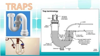
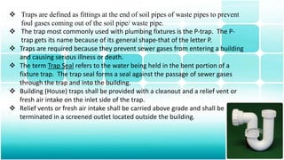
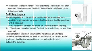
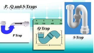
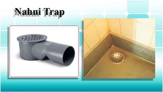
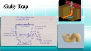
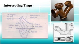
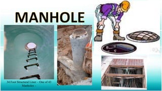


Traps are fittings used to prevent foul gases from entering buildings through soil or waste pipes. Traps retain a small amount of water that forms a seal against gas passage. They are usually P-shaped and must be self-cleaning to allow waste to pass through while maintaining the water seal. Manholes provide access for maintenance of underground utility lines like sewers. They have protective covers and steps within to access the underground space safely. Proper installation and design of manholes and their supports is needed to prevent structural failures over time.


