The document provides details on the design of a sewer system for a housing society located in Jhelum, Pakistan. It includes preliminary investigations of the site, design considerations and criteria, and calculations for pipe sizing and slope between manholes. The design is based on a population forecast of 319 people in the future with an average daily sewage flow of 115 cubic meters and peak flow of 467 cubic meters. Calculations show a 225mm diameter pipe is required between the first two manholes with a slope of 0.0033 to maintain a minimum velocity of 0.7 meters per second.


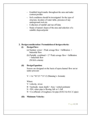

![DESIGN CALCULATIONS
POPULATION FORCASTING:
Population Present Future
(2017) (2037)
Persons/plot 7 11
Persons/app 400 618
Persons/flat 200 309
Pop. of school 300 464
Park 200 309
Graveyard 50 77
Dispensary 150 232
Presentpopulation:
(No. of plots * no. of persons per plot) + other population
Design future population:
Pi + [1+ % rate of growth]
Here n = no. of years for design
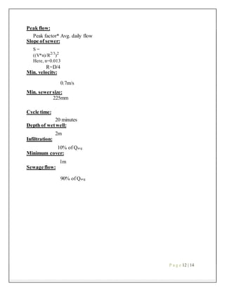
Per capita waterconsumption:
400 lpcd
Avg. daily flow:
(Population*per capita consumption*factor)/1000
Here, Factor= 0.8 to 0.9
Peak factor:
1+ (14/4+P.05
)
Here, P = in thousands
P a g e 11 | 14](https://image.slidesharecdn.com/arslan-180423112533/85/SEWER-DESIGN-12-320.jpg)