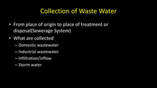
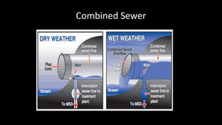
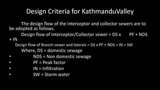
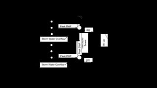
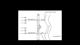
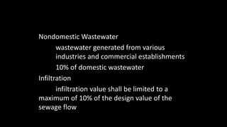
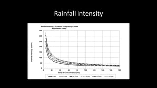
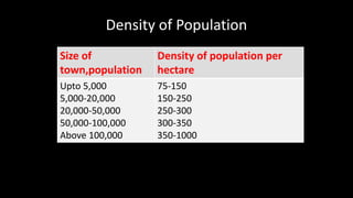
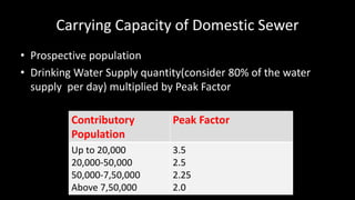
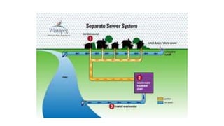
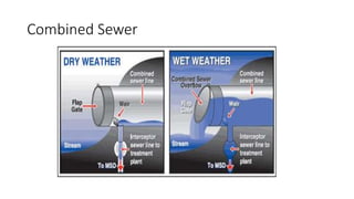
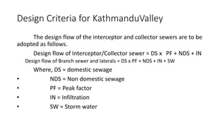
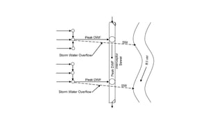
Rajesh Prasad Singh
Prepared by:
Collection of Waste Water
• From place of origin to place of treatment or
disposal(Sewerage System)
• What are collected
– Domestic wastewater
– Industrial wastewater
– Infiltration/inflow
– Storm water
Types of Collection System
1)Sanitary wastewater system
2)Combined sanitary and storm water collection system
3)Storm water collection system
Choice of System
Combined System Separate system
Volume of water reaching WWTP High
Sewer size Large
Self cleansing velocity during dry period
LOW, so deposits of solid in the sewer
Initial investment HIGH
Low
Smaller size
Basis of design is the required self
cleansing velocity
Low
Combined Sewer
Water
Quality
Standards
for Various
uses
Design Criteria for KathmanduValley
The design flow of the interceptor and collector sewers are to
be adopted as follows.
Design flow of Interceptor/Collector sewer = DS x PF + NDS
+ IN
Design flow of Branch sewer and laterals = DS x PF + NDS + IN + SW
Where, DS = domestic sewage
• NDS = Non domestic sewage
• PF = Peak factor
• IN = Infiltration
• SW = Storm water
Steps in Sewer Design
• Survey and General Investigation
– Precise levels indicating the topography
– Subsoil investigation
– Location of treatment works
– Existing features of the town
– Type of land use
– Population and population density
– Discharge point of the water body with HFL
– One meter contour map
– Existing utilities to be mapped in the layout plan
• System Pattern of Sewerage Layout
– Interceptor pattern
– Zone pattern
– Fan Pattern
– Radial Pattern
• Design Period
Minimum 30 years
• Population
– Use census data
– Real count
– Make projection of future population
– Use population densities where there is possibility of growth in the
future
Wastewater Generation
• Domestic Wastewater
– 100 lpcd up to the year 2020 and 120 lpcd in the year 2030
– 80% of the water consumption becoming sewage flow("Manual on
Sewerage and Sewage Treatment”, Ministry of Urban Development,
November 2013)
Nondomestic Wastewater
wastewater generated from various
industries and commercial establishments
10% of domestic wastewater
Infiltration
infiltration value shall be limited to a
maximum of 10% of the design value of the
sewage flow
Storm Water
Q = CIA
where, Q = storm water flow in m3/s; C = runoff
coefficient or impermeability factor;
I = intensity of rainfall in m/s; and
A=catchment area or drainage area in m2
Runoff Coefficient(C)
Land Use
Runoff
Coefficient
Land Use
Runoff
Coefficient
Lawns:
Sandy soil, flat, 2% 0.05 - 0.10
Business: Sandy soil, avg., 2-7% 0.10 - 0.15
Downtown area 0.70 - 0.95 Sandy soil, steep, 7% 0.15 - 0.20
Neighborhood area 0.50 - 0.70 Heavy soil, flat, 2% 0.13 - 0.17
Heavy soil, avg., 2-7% 0.18 - 0.22
Heavy soil, steep, 7% 0.25 - 0.35
Agricultural land:
Bare packed soil
Smooth 0.30 - 0.60
Rough 0.20 - 0.50
Residential (urban): Cultivated rows
Single family area 0.30 - 0.50 Heavy soil, no crop 0.30 - 0.60
Multi-units, detached 0.40 - 0.60 Heavy soil, with crop 0.20 - 0.50
Multi-units, attached 0.60 - 0.75 Sandy soil, no crop 0.20 - 0.40
Residential (suburban) 0.25 - 0.40 Sandy soil, with crop 0.10 - 0.25
Apartment areas 0.50 - 0.70 Pasture
Heavy soil 0.15 - 0.45
Sandy soil 0.05 - 0.25
Woodlands 0.05 - 0.25
Streets:
Industrial Asphaltic 0.70 - 0.95
Light areas 0.50 - 0.80 Concrete 0.80 - 0.95
Heavy areas 0.60 - 0.90 Brick 0.70 - 0.85
Parks, cemeteries 0.10 - 0.25 Unimproved areas 0.10 - 0.30
Playgrounds 0.20 - 0.35 Drives and walks 0.75 - 0.85
Railroad yards 0.20 - 0.40 Roofs 0.75 - 0.95
Coefficients
Rainfall Intensity
0
50
100
150
200
250
300
350
0 20 40 60 80 100 120 140 160 180
RainfalIntensity(mm/hr)
Time of Concentration (min)
Rainfall Intensity - Duration - Frequency Curves
Kathmandu Valley
2-year 5-year 10-year 25-year 50-year 100-year
Flow Velocity
• Self Cleaning Velocity
– The minimum velocity at which no solids get deposited in the invert
of the sewer is called self-cleaning velocity. For the design purposes
the self- cleaning velocity has considered as 0.6 m/sec (source:
American Society of Civil Engineers, ASCE).
• The minimum velocity to cause the scouring of the suspension
of solids heavier than the sewage or liquid which carry them is
determined by the following Shield formula:
V =
8k
f
ρs−ρ
ρ
g × d
Where, V = Velocity of flow
k = Characteristics of solids (0.04 -0.06)
• f = Darcy’s coefficient of friction, 0.03
Specific gravity of the solids particles in the
sewage. Its value is between 1.2 and 2.65.
• Specific gravity of the liquid = 1
• g = Acceleration due to gravity
• d = diameter of the particles.
• From the above formula, it is clear that heavier and
sticky solids require velocity for their cleaning.
=
Minimum Velocity
The minimum velocity of 0.6 and 0.8 m/s at the peak flow is
recommended for separate flow and combined/storm water
sewer respectively
Maximum Velocity
The maximum velocity of 3.0 m/sec has been recommended.
Froude number should be less than 1.0 so that supercritical flow
is avoided at the peak flow.
Design Formula
• Design practice is to use Manning’s Formula for open channel
flow and the Hazen Williams and Darcy-Weisbach formulae for
closed conduit or pressure flow (Source: Manual on Sewerage
and Sewage Treatment (Third Edition), Ministry of Urban
Development, November 2013).
The manning's formula is given by the following equation.
V =
1
n
× R
2
3 × S
1
2
Q =
1
n
× A × R
2
3 × S
1
2
Where;
Q = discharge in m3/s
S = slope of hydraulic gradient
R = hydraulic radius in m
A = cross sectional area of flow
V= velocity in m/s
n = Manning’s coefficient of roughness
Roughness Coefficient
Manning roughness coefficients for concrete and HDPE pipes are
recommended as 0.013 and 0.009 respectively
Minimum Sewer Diameter
200 mm for collector, branch and lateral sewers 400 mm for
interceptor sewers
Ruling Gradient
CWWMP recommends a minimum sewer gradient of 1 in 200
Depth of Flow in Sewer
Sewers will be designed in such a way that the depth of flow in
the sewer at peak flow is not more than 0.8 times the diameter
of the sewer i.e. d/D ≤ 0.8
Pipe Features
Pipe Material and Joints
In principle all pipes to be used in the main sewer network
are proposed to be reinforced concrete cement RCC pipes with
spigot and socket ends, jointed through rubber gaskets. RCC
pipes shall be manufactured as per NS80/2042 and IS 458:2003
medium duty, non pressure pipes. The jointing shall be Rubber
Ring Joint (RRJ) type and the rubber gasket to be provided shall
be as per NS, NP3 or exceptionally NP4 RCC (Hume) pipes for
sewer lines as applicable.
Pipe Cover
The minimum cover above the crests of the sewer pipe is to be 1.0 m
Width of Trench
• For diameter up to 450mm, the bottom pipe width of trench shall be
OD+45cm
• For diameter above 450 mm, the bottom width of trench shall be
OD+60cm
• For house connection, the bottom width of trench shall be not less than
OD+30cm
Where OD = outside diameter of pipe
Bedding
Table 3-2: Categories of Bedding
Category
Description Abbreviation
Type 1 Granular bedding GRB
Type 2 Plain Cement Concrete M20 PCCB
Type 3 Reinforced Cement Concrete 0.4%
reinforcement M20
RCCB 0.4
Type 4 Reinforced Cement Concrete 1.0%
reinforcement M20
RCCB 1.0
Type 5
"Arch" bedding for PE pipes including the
combination of anti-flotation precast RCC
blocks every 3m and type 1 bedding in current
sections
ARCH / Type 1
Table 3.3
The proposed bedding type for various pipe materials at different
depths are specified in Table 3-3 and Table 3-4.
Pipe
NP3 -RRJ
Type 1 Type 2 Type 3 Type 4 Type 5
ND OD GRB PCCB RCCB 0.4 RCCB
1.0
ARCH
200 0.26 0-4m 5. m >5m
IfRequired
NotApplicable
250 0.31 0-4m 4-5m >5m
300 0.38 0-4m 4-5m >5m
350 0.50 0-4m 4-5m >5m
400 0.55 0-4m 4-5m >5m
450 0.60 0-4m 4-5m >5m
500 0.65 0-5m 5-6m >6m
600 0.77 0-5m 5-6m >6m
700 0.87 0-5m 5-6m >6m
800 0.99 0-5m 5-6m >6m
900 1.10 0-5m 5-6m >6m
1000 1.23
Not
Applicable
0-7m >7m
1200 1.44 0-7m >7m
1500 1.78 0-7m >7m
Depth Of Trench
Trench Depth = Ground Level – Invert Level + Pipe Thickness + H1
Where, H1 is related to thetype of bedding
H2 and H3 are related to the pipe diameter
H4 is related to the type of bedding
H5 depend of the bedding arrangements and the surface reinstatement
H6 is defined by the characteristics of the surface finishing
H2 + H3 is equal to the outside diameter of the pipe
The concrete cradle depth varies from 0 to H1+H2+H3+H4 depending on the type of bedding.
Density of Population
Size of
town,population
Density of population per
hectare
Upto 5,000
5,000-20,000
20,000-50,000
50,000-100,000
Above 100,000
75-150
150-250
250-300
300-350
350-1000
Carrying Capacity of Domestic Sewer
• Prospective population
• Drinking Water Supply quantity(consider 80% of the water
supply per day) multiplied by Peak Factor
Contributory
Population
Peak Factor
Up to 20,000
20,000-50,000
50,000-7,50,000
Above 7,50,000
3.5
2.5
2.25
2.0
Flow depth in sewer
• Due to ventilation in waste water flow, sewers are not
designed to run full
• Recommended Depth of Flow in Sewers
Size of Sewer Depth of Flow
Upto 400 mm dia
400mm-900mm dia
Larger than 900mmdia
½ depth
2/3 depth
¾ depth
Minimum Size of Sewer
Minimum size of public sewer shall be 150mm dia but
in practice 200mm dia is recommended
Minimum And Maximum Velocity
Sewer should constructed with gradients which
produce Self Cleansing Velocities sufficient to carry
forward all solids and avoid settlements. A minimum
velocity of 0.6m/sec at design peak flow in the sewer
is recommended subject to a minimum velocity of
0.6m/sec for Present Peak Flows.The maximum
velocity to be permitted is of the order of 3m/sec
Manholes
Purpose of manholes
cleaning, inspection and maintenance of sewer line
Location of manholes
gradient change
pipe size change
bends
regular interval as per specification
Construction Material
• Manholes are generally constructed in circular shape. The manholes are in brick masonry
walls with plastered inside, RC concrete bottom and top slab with cover and finished with a
benching. Alternatively small size masonry manholes can be rectangular for easy
construction
• Where the water table is high and the pipe sewer is laid in open field or along the side of
the drain, the RCC circular manholes would be constructed to avoid any leakages into or out
the manholes. The RCC cast in situ or precast manholes will be used in the interceptor and
collector sewers as these are proposed to be laid along the bank of the river. RCC precast or
cast in situ manholes are recommended for large size sewers where space is sufficient for its
construction. If possible brick masonry manholes are planned for narrow streets where the
construction of RCC manholes is difficult and RCC cast in situ or precast manholes are
proposed for main roads or for heavy traffic roads. Precast manholes should be made
watertight by providing rubber gasket at the joints. Masonry manholes are limited to 2 m
depth for pipes of 200-450 mm.
Manhole Cover Levels
• The final level of manholes would be depending on site condition,
and therefore the final levels will be finalized during the execution
time. However, generally the following values may be considered;
• Paved areas cover level = final paved level.
• Landscaped areas cover level = final ground level +0.1m.
• Open, unpaved areas cover level = final ground level +0.25m or as
instructed by the Engineer during construction.
• Manhole covers with frame with a minimum clear opening of 600
mm
Manhole Size and Shape
Table 3-7: Recommended Manhole Size
Depth to Pipe Soffit from Cover
Level
Largest Pipe in Manhole Circular Diameter of Manhole Wall Thickness
Manhole Type
(m) (mm) (mm) (mm)
< 3 200-450 900 150 Type I RCC
3 - 6 200-450 1200 200 Type II RCC
< 5 500-1000 1500 200 Type III RCC
5 - 8 500-1000 1500 250 Type IV RCC
< 5 1200 1800 200 Type V RCC
5 - 8 1200 1800 250 Type VI RCC
< 5 1400-1600 2400 200 Type VII RCC
5 - 8 1400-1600 2400 250 Type VIII RCC
Thank you
Collection of Waste Water
• From place of origin to place of treatment or disposal(Sewerage
System)
• What are collected
• Domestic wastewater
• Industrial wastewater
• Infiltration/inflow
• Storm water
Types of Collection System
1)Sanitary wastewater system
2)Combined sanitary and storm water collection system
3)Storm water collection system
Choice of System
Combined System Separate system
Volume of water reaching WWTP High
Sewer size Large
Self cleansing velocity during dry period
LOW, so deposits of solid in the sewer
Initial investment HIGH
Low
Smaller size
Basis of design is the required self
cleansing velocity
Low
Combined Sewer
Water
Quality
Standards
for Various
uses
Design Criteria for KathmanduValley
The design flow of the interceptor and collector sewers are to be
adopted as follows.
Design flow of Interceptor/Collector sewer = DS x PF + NDS + IN
Design flow of Branch sewer and laterals = DS x PF + NDS + IN + SW
Where, DS = domestic sewage
• NDS = Non domestic sewage
• PF = Peak factor
• IN = Infiltration
• SW = Storm water
Steps in Sewer Design
• Survey and General Investigation
• Precise levels indicating the topography
• Subsoil investigation
• Location of treatment works
• Existing features of the town
• Type of land use
• Population and population density
• Discharge point of the water body with HFL
• One meter contour map
• Existing utilities to be mapped in the layout plan
• System Pattern of Sewerage Layout
• Interceptor pattern
• Zone pattern
• Fan Pattern
• Radial Pattern
• Design Period
Minimum 30 years
• Population
• Use census data
• Real count
• Make projection of future population
• Use population densities where there is possibility of growth in the future
Wastewater Generation
• Domestic Wastewater
• 100 lpcd up to the year 2020 and 120 lpcd in the year 2030
• 80% of the water consumption becoming sewage flow("Manual on Sewerage
and Sewage Treatment”, Ministry of Urban Development, November 2013)
Nondomestic Wastewater
wastewater generated from various industries
and commercial establishments
10% of domestic wastewater
Infiltration
infiltration value shall be limited to a maximum
of 10% of the design value of the sewage flow
Storm Water
Q = CIA
where, Q = storm water flow in m3/s; C = runoff
coefficient or impermeability factor;
I = intensity of rainfall in m/s; and
A=catchment area or drainage area in m2
Runoff Coefficient(C)
Land Use
Runoff
Coefficient
Land Use
Runoff
Coefficient
Lawns:
Sandy soil, flat, 2% 0.05 - 0.10
Business: Sandy soil, avg., 2-7% 0.10 - 0.15
Downtown area 0.70 - 0.95 Sandy soil, steep, 7% 0.15 - 0.20
Neighborhood area 0.50 - 0.70 Heavy soil, flat, 2% 0.13 - 0.17
Heavy soil, avg., 2-7% 0.18 - 0.22
Heavy soil, steep, 7% 0.25 - 0.35
Agricultural land:
Bare packed soil
Smooth 0.30 - 0.60
Rough 0.20 - 0.50
Residential (urban): Cultivated rows
Single family area 0.30 - 0.50 Heavy soil, no crop 0.30 - 0.60
Multi-units, detached 0.40 - 0.60 Heavy soil, with crop 0.20 - 0.50
Multi-units, attached 0.60 - 0.75 Sandy soil, no crop 0.20 - 0.40
Residential (suburban) 0.25 - 0.40 Sandy soil, with crop 0.10 - 0.25
Apartment areas 0.50 - 0.70 Pasture
Heavy soil 0.15 - 0.45
Sandy soil 0.05 - 0.25
Woodlands 0.05 - 0.25
Streets:
Industrial Asphaltic 0.70 - 0.95
Light areas 0.50 - 0.80 Concrete 0.80 - 0.95
Heavy areas 0.60 - 0.90 Brick 0.70 - 0.85
Parks, cemeteries 0.10 - 0.25 Unimproved areas 0.10 - 0.30
Playgrounds 0.20 - 0.35 Drives and walks 0.75 - 0.85
Railroad yards 0.20 - 0.40 Roofs 0.75 - 0.95
Coefficients
Rainfall Intensity
0
50
100
150
200
250
300
350
0 20 40 60 80 100 120 140 160 180
RainfalIntensity(mm/hr)
Time of Concentration (min)
Rainfall Intensity - Duration - Frequency Curves
Kathmandu Valley
2-year 5-year 10-year 25-year 50-year 100-year
Flow Velocity
• Self Cleaning Velocity
• The minimum velocity at which no solids get deposited in the invert of the
sewer is called self-cleaning velocity. For the design purposes the self-
cleaning velocity has considered as 0.6 m/sec (source: American Society of
Civil Engineers, ASCE).
• The minimum velocity to cause the scouring of the suspension of
solids heavier than the sewage or liquid which carry them is
determined by the following Shield formula:
V =
8k
f
ρs−ρ
ρ
g × d
Where, V = Velocity of flow
k = Characteristics of solids (0.04 -0.06)
• f = Darcy’s coefficient of friction, 0.03
Specific gravity of the solids particles in the
sewage. Its value is between 1.2 and 2.65.
• Specific gravity of the liquid = 1
• g = Acceleration due to gravity
• d = diameter of the particles.
• From the above formula, it is clear that heavier and sticky
solids require velocity for their cleaning.
=
Minimum Velocity
The minimum velocity of 0.6 and 0.8 m/s at the peak flow is
recommended for separate flow and combined/storm water sewer
respectively
Maximum Velocity
The maximum velocity of 3.0 m/sec has been recommended. Froude
number should be less than 1.0 so that supercritical flow is avoided at
the peak flow.
Design Formula
• Design practice is to use Manning’s Formula for open channel flow
and the Hazen Williams and Darcy-Weisbach formulae for closed
conduit or pressure flow (Source: Manual on Sewerage and Sewage
Treatment (Third Edition), Ministry of Urban Development, November
2013).
The manning's formula is given by the following equation.
V =
1
n
× R
2
3 × S
1
2
Q =
1
n
× A × R
2
3 × S
1
2
Where;
Q = discharge in m3/s
S = slope of hydraulic gradient
R = hydraulic radius in m
A = cross sectional area of flow
V= velocity in m/s
n = Manning’s coefficient of roughness
Roughness Coefficient
Manning roughness coefficients for concrete and HDPE pipes are
recommended as 0.013 and 0.009 respectively
Minimum Sewer Diameter
200 mm for collector, branch and lateral sewers 400 mm for
interceptor sewers
Ruling Gradient
CWWMP recommends a minimum sewer gradient of 1 in 200
Depth of Flow in Sewer
Sewers will be designed in such a way that the depth of flow in the
sewer at peak flow is not more than 0.8 times the diameter of the
sewer i.e. d/D ≤ 0.8
Pipe Features
Pipe Material and Joints
In principle all pipes to be used in the main sewer network are
proposed to be reinforced concrete cement RCC pipes with spigot and
socket ends, jointed through rubber gaskets. RCC pipes shall be
manufactured as per NS80/2042 and IS 458:2003 medium duty, non
pressure pipes. The jointing shall be Rubber Ring Joint (RRJ) type and
the rubber gasket to be provided shall be as per NS, NP3 or
exceptionally NP4 RCC (Hume) pipes for sewer lines as applicable.
Pipe Cover
The minimum cover above the crests of the sewer pipe is to be 1.0 m
Width of Trench
• For diameter up to 450mm, the bottom pipe width of trench shall be
OD+45cm
• For diameter above 450 mm, the bottom width of trench shall be
OD+60cm
• For house connection, the bottom width of trench shall be not less than
OD+30cm
Where OD = outside diameter of pipe
Bedding
Table 3-2: Categories of Bedding
Category
Description Abbreviation
Type 1 Granular bedding GRB
Type 2 Plain Cement Concrete M20 PCCB
Type 3 Reinforced Cement Concrete 0.4%
reinforcement M20
RCCB 0.4
Type 4 Reinforced Cement Concrete 1.0%
reinforcement M20
RCCB 1.0
Type 5
"Arch" bedding for PE pipes including the
combination of anti-flotation precast RCC
blocks every 3m and type 1 bedding in current
sections
ARCH / Type 1
Table 3.3
The proposed bedding type for various pipe materials at different
depths are specified in Table 3-3 and Table 3-4.
Pipe
NP3 -RRJ
Type 1 Type 2 Type 3 Type 4 Type 5
ND OD GRB PCCB RCCB 0.4 RCCB
1.0
ARCH
200 0.26 0-4m 5. m >5m
IfRequired
NotApplicable
250 0.31 0-4m 4-5m >5m
300 0.38 0-4m 4-5m >5m
350 0.50 0-4m 4-5m >5m
400 0.55 0-4m 4-5m >5m
450 0.60 0-4m 4-5m >5m
500 0.65 0-5m 5-6m >6m
600 0.77 0-5m 5-6m >6m
700 0.87 0-5m 5-6m >6m
800 0.99 0-5m 5-6m >6m
900 1.10 0-5m 5-6m >6m
1000 1.23
Not
Applicable
0-7m >7m
1200 1.44 0-7m >7m
1500 1.78 0-7m >7m
Depth Of Trench
Trench Depth = Ground Level – Invert Level + Pipe Thickness + H1
Where, H1 is related to thetype of bedding
H2 and H3 are related to the pipe diameter
H4 is related to the type of bedding
H5 depend of the bedding arrangements and the surface reinstatement
H6 is defined by the characteristics of the surface finishing
H2 + H3 is equal to the outside diameter of the pipe
The concrete cradle depth varies from 0 to H1+H2+H3+H4 depending on the type of bedding.
Density of Population
Size of
town,population
Density of population per
hectare
Upto 5,000
5,000-20,000
20,000-50,000
50,000-100,000
Above 100,000
75-150
150-250
250-300
300-350
350-1000
Carrying Capacity of Domestic Sewer
• Prospective population
• Drinking Water Supply quantity(consider 80% of the water supply per
day) multiplied by Peak Factor
Contributory
Population
Peak Factor
Up to 20,000
20,000-50,000
50,000-7,50,000
Above 7,50,000
3.5
2.5
2.25
2.0
Flow depth in sewer
• Due to ventilation in waste water flow, sewers are not designed to run
full
• Recommended Depth of Flow in Sewers
Size of Sewer Depth of Flow
Upto 400 mm dia
400mm-900mm dia
Larger than 900mmdia
½ depth
2/3 depth
¾ depth
Minimum Size of Sewer
Minimum size of public sewer shall be 150mm dia but
in practice 200mm dia is recommended
Minimum And Maximum Velocity
Sewer should constructed with gradients which
produce Self Cleansing Velocities sufficient to carry
forward all solids and avoid settlements. A minimum
velocity of 0.6m/sec at design peak flow in the sewer
is recommended subject to a minimum velocity of
0.6m/sec for Present Peak Flows.The maximum
velocity to be permitted is of the order of 3m/sec
Manholes
Purpose of manholes
cleaning, inspection and maintenance of sewer line
Location of manholes
gradient change
pipe size change
bends
regular interval as per specification
Construction Material
• Manholes are generally constructed in circular shape. The manholes are in brick masonry
walls with plastered inside, RC concrete bottom and top slab with cover and finished
with a benching. Alternatively small size masonry manholes can be rectangular for easy
construction
• Where the water table is high and the pipe sewer is laid in open field or along the side of
the drain, the RCC circular manholes would be constructed to avoid any leakages into or
out the manholes. The RCC cast in situ or precast manholes will be used in the
interceptor and collector sewers as these are proposed to be laid along the bank of the
river. RCC precast or cast in situ manholes are recommended for large size sewers where
space is sufficient for its construction. If possible brick masonry manholes are planned
for narrow streets where the construction of RCC manholes is difficult and RCC cast in
situ or precast manholes are proposed for main roads or for heavy traffic roads. Precast
manholes should be made watertight by providing rubber gasket at the joints. Masonry
manholes are limited to 2 m depth for pipes of 200-450 mm.
Manhole Cover Levels
• The final level of manholes would be depending on site condition,
and therefore the final levels will be finalized during the execution
time. However, generally the following values may be considered;
• Paved areas cover level = final paved level.
• Landscaped areas cover level = final ground level +0.1m.
• Open, unpaved areas cover level = final ground level +0.25m or as
instructed by the Engineer during construction.
• Manhole covers with frame with a minimum clear opening of 600 mm
Manhole Size and Shape
Table 3-7: Recommended Manhole Size
Depth to Pipe Soffit from Cover
Level
Largest Pipe in Manhole Circular Diameter of Manhole Wall Thickness
Manhole Type
(m) (mm) (mm) (mm)
< 3 200-450 900 150 Type I RCC
3 - 6 200-450 1200 200 Type II RCC
< 5 500-1000 1500 200 Type III RCC
5 - 8 500-1000 1500 250 Type IV RCC
< 5 1200 1800 200 Type V RCC
5 - 8 1200 1800 250 Type VI RCC
< 5 1400-1600 2400 200 Type VII RCC
5 - 8 1400-1600 2400 250 Type VIII RCC
Thank you

Sewer Design

  • 1.
  • 2.
    Collection of WasteWater • From place of origin to place of treatment or disposal(Sewerage System) • What are collected – Domestic wastewater – Industrial wastewater – Infiltration/inflow – Storm water
  • 3.
    Types of CollectionSystem 1)Sanitary wastewater system 2)Combined sanitary and storm water collection system 3)Storm water collection system
  • 4.
    Choice of System CombinedSystem Separate system Volume of water reaching WWTP High Sewer size Large Self cleansing velocity during dry period LOW, so deposits of solid in the sewer Initial investment HIGH Low Smaller size Basis of design is the required self cleansing velocity Low
  • 6.
  • 7.
  • 8.
    Design Criteria forKathmanduValley The design flow of the interceptor and collector sewers are to be adopted as follows. Design flow of Interceptor/Collector sewer = DS x PF + NDS + IN Design flow of Branch sewer and laterals = DS x PF + NDS + IN + SW Where, DS = domestic sewage • NDS = Non domestic sewage • PF = Peak factor • IN = Infiltration • SW = Storm water
  • 11.
    Steps in SewerDesign • Survey and General Investigation – Precise levels indicating the topography – Subsoil investigation – Location of treatment works – Existing features of the town – Type of land use – Population and population density – Discharge point of the water body with HFL
  • 12.
    – One metercontour map – Existing utilities to be mapped in the layout plan
  • 13.
    • System Patternof Sewerage Layout – Interceptor pattern – Zone pattern – Fan Pattern – Radial Pattern • Design Period Minimum 30 years
  • 14.
    • Population – Usecensus data – Real count – Make projection of future population – Use population densities where there is possibility of growth in the future
  • 15.
    Wastewater Generation • DomesticWastewater – 100 lpcd up to the year 2020 and 120 lpcd in the year 2030 – 80% of the water consumption becoming sewage flow("Manual on Sewerage and Sewage Treatment”, Ministry of Urban Development, November 2013)
  • 16.
    Nondomestic Wastewater wastewater generatedfrom various industries and commercial establishments 10% of domestic wastewater Infiltration infiltration value shall be limited to a maximum of 10% of the design value of the sewage flow
  • 17.
    Storm Water Q =CIA where, Q = storm water flow in m3/s; C = runoff coefficient or impermeability factor; I = intensity of rainfall in m/s; and A=catchment area or drainage area in m2
  • 18.
    Runoff Coefficient(C) Land Use Runoff Coefficient LandUse Runoff Coefficient Lawns: Sandy soil, flat, 2% 0.05 - 0.10 Business: Sandy soil, avg., 2-7% 0.10 - 0.15 Downtown area 0.70 - 0.95 Sandy soil, steep, 7% 0.15 - 0.20 Neighborhood area 0.50 - 0.70 Heavy soil, flat, 2% 0.13 - 0.17 Heavy soil, avg., 2-7% 0.18 - 0.22 Heavy soil, steep, 7% 0.25 - 0.35 Agricultural land: Bare packed soil Smooth 0.30 - 0.60 Rough 0.20 - 0.50 Residential (urban): Cultivated rows Single family area 0.30 - 0.50 Heavy soil, no crop 0.30 - 0.60 Multi-units, detached 0.40 - 0.60 Heavy soil, with crop 0.20 - 0.50 Multi-units, attached 0.60 - 0.75 Sandy soil, no crop 0.20 - 0.40 Residential (suburban) 0.25 - 0.40 Sandy soil, with crop 0.10 - 0.25 Apartment areas 0.50 - 0.70 Pasture Heavy soil 0.15 - 0.45 Sandy soil 0.05 - 0.25 Woodlands 0.05 - 0.25 Streets: Industrial Asphaltic 0.70 - 0.95 Light areas 0.50 - 0.80 Concrete 0.80 - 0.95 Heavy areas 0.60 - 0.90 Brick 0.70 - 0.85 Parks, cemeteries 0.10 - 0.25 Unimproved areas 0.10 - 0.30 Playgrounds 0.20 - 0.35 Drives and walks 0.75 - 0.85 Railroad yards 0.20 - 0.40 Roofs 0.75 - 0.95 Coefficients
  • 19.
    Rainfall Intensity 0 50 100 150 200 250 300 350 0 2040 60 80 100 120 140 160 180 RainfalIntensity(mm/hr) Time of Concentration (min) Rainfall Intensity - Duration - Frequency Curves Kathmandu Valley 2-year 5-year 10-year 25-year 50-year 100-year
  • 20.
    Flow Velocity • SelfCleaning Velocity – The minimum velocity at which no solids get deposited in the invert of the sewer is called self-cleaning velocity. For the design purposes the self- cleaning velocity has considered as 0.6 m/sec (source: American Society of Civil Engineers, ASCE).
  • 21.
    • The minimumvelocity to cause the scouring of the suspension of solids heavier than the sewage or liquid which carry them is determined by the following Shield formula: V = 8k f ρs−ρ ρ g × d
  • 22.
    Where, V =Velocity of flow k = Characteristics of solids (0.04 -0.06) • f = Darcy’s coefficient of friction, 0.03 Specific gravity of the solids particles in the sewage. Its value is between 1.2 and 2.65. • Specific gravity of the liquid = 1 • g = Acceleration due to gravity • d = diameter of the particles. • From the above formula, it is clear that heavier and sticky solids require velocity for their cleaning. =
  • 23.
    Minimum Velocity The minimumvelocity of 0.6 and 0.8 m/s at the peak flow is recommended for separate flow and combined/storm water sewer respectively Maximum Velocity The maximum velocity of 3.0 m/sec has been recommended. Froude number should be less than 1.0 so that supercritical flow is avoided at the peak flow.
  • 24.
    Design Formula • Designpractice is to use Manning’s Formula for open channel flow and the Hazen Williams and Darcy-Weisbach formulae for closed conduit or pressure flow (Source: Manual on Sewerage and Sewage Treatment (Third Edition), Ministry of Urban Development, November 2013).
  • 25.
    The manning's formulais given by the following equation. V = 1 n × R 2 3 × S 1 2 Q = 1 n × A × R 2 3 × S 1 2 Where; Q = discharge in m3/s S = slope of hydraulic gradient R = hydraulic radius in m A = cross sectional area of flow V= velocity in m/s n = Manning’s coefficient of roughness
  • 26.
    Roughness Coefficient Manning roughnesscoefficients for concrete and HDPE pipes are recommended as 0.013 and 0.009 respectively Minimum Sewer Diameter 200 mm for collector, branch and lateral sewers 400 mm for interceptor sewers
  • 27.
    Ruling Gradient CWWMP recommendsa minimum sewer gradient of 1 in 200 Depth of Flow in Sewer Sewers will be designed in such a way that the depth of flow in the sewer at peak flow is not more than 0.8 times the diameter of the sewer i.e. d/D ≤ 0.8
  • 28.
    Pipe Features Pipe Materialand Joints In principle all pipes to be used in the main sewer network are proposed to be reinforced concrete cement RCC pipes with spigot and socket ends, jointed through rubber gaskets. RCC pipes shall be manufactured as per NS80/2042 and IS 458:2003 medium duty, non pressure pipes. The jointing shall be Rubber Ring Joint (RRJ) type and the rubber gasket to be provided shall be as per NS, NP3 or exceptionally NP4 RCC (Hume) pipes for sewer lines as applicable.
  • 29.
    Pipe Cover The minimumcover above the crests of the sewer pipe is to be 1.0 m Width of Trench • For diameter up to 450mm, the bottom pipe width of trench shall be OD+45cm • For diameter above 450 mm, the bottom width of trench shall be OD+60cm • For house connection, the bottom width of trench shall be not less than OD+30cm Where OD = outside diameter of pipe
  • 30.
    Bedding Table 3-2: Categoriesof Bedding Category Description Abbreviation Type 1 Granular bedding GRB Type 2 Plain Cement Concrete M20 PCCB Type 3 Reinforced Cement Concrete 0.4% reinforcement M20 RCCB 0.4 Type 4 Reinforced Cement Concrete 1.0% reinforcement M20 RCCB 1.0 Type 5 "Arch" bedding for PE pipes including the combination of anti-flotation precast RCC blocks every 3m and type 1 bedding in current sections ARCH / Type 1
  • 31.
    Table 3.3 The proposedbedding type for various pipe materials at different depths are specified in Table 3-3 and Table 3-4. Pipe NP3 -RRJ Type 1 Type 2 Type 3 Type 4 Type 5 ND OD GRB PCCB RCCB 0.4 RCCB 1.0 ARCH 200 0.26 0-4m 5. m >5m IfRequired NotApplicable 250 0.31 0-4m 4-5m >5m 300 0.38 0-4m 4-5m >5m 350 0.50 0-4m 4-5m >5m 400 0.55 0-4m 4-5m >5m 450 0.60 0-4m 4-5m >5m 500 0.65 0-5m 5-6m >6m 600 0.77 0-5m 5-6m >6m 700 0.87 0-5m 5-6m >6m 800 0.99 0-5m 5-6m >6m 900 1.10 0-5m 5-6m >6m 1000 1.23 Not Applicable 0-7m >7m 1200 1.44 0-7m >7m 1500 1.78 0-7m >7m
  • 32.
    Depth Of Trench TrenchDepth = Ground Level – Invert Level + Pipe Thickness + H1 Where, H1 is related to thetype of bedding H2 and H3 are related to the pipe diameter H4 is related to the type of bedding H5 depend of the bedding arrangements and the surface reinstatement H6 is defined by the characteristics of the surface finishing H2 + H3 is equal to the outside diameter of the pipe The concrete cradle depth varies from 0 to H1+H2+H3+H4 depending on the type of bedding.
  • 34.
    Density of Population Sizeof town,population Density of population per hectare Upto 5,000 5,000-20,000 20,000-50,000 50,000-100,000 Above 100,000 75-150 150-250 250-300 300-350 350-1000
  • 35.
    Carrying Capacity ofDomestic Sewer • Prospective population • Drinking Water Supply quantity(consider 80% of the water supply per day) multiplied by Peak Factor Contributory Population Peak Factor Up to 20,000 20,000-50,000 50,000-7,50,000 Above 7,50,000 3.5 2.5 2.25 2.0
  • 36.
    Flow depth insewer • Due to ventilation in waste water flow, sewers are not designed to run full • Recommended Depth of Flow in Sewers Size of Sewer Depth of Flow Upto 400 mm dia 400mm-900mm dia Larger than 900mmdia ½ depth 2/3 depth ¾ depth
  • 38.
    Minimum Size ofSewer Minimum size of public sewer shall be 150mm dia but in practice 200mm dia is recommended Minimum And Maximum Velocity Sewer should constructed with gradients which produce Self Cleansing Velocities sufficient to carry forward all solids and avoid settlements. A minimum velocity of 0.6m/sec at design peak flow in the sewer is recommended subject to a minimum velocity of 0.6m/sec for Present Peak Flows.The maximum velocity to be permitted is of the order of 3m/sec
  • 39.
    Manholes Purpose of manholes cleaning,inspection and maintenance of sewer line Location of manholes gradient change pipe size change bends regular interval as per specification
  • 40.
    Construction Material • Manholesare generally constructed in circular shape. The manholes are in brick masonry walls with plastered inside, RC concrete bottom and top slab with cover and finished with a benching. Alternatively small size masonry manholes can be rectangular for easy construction • Where the water table is high and the pipe sewer is laid in open field or along the side of the drain, the RCC circular manholes would be constructed to avoid any leakages into or out the manholes. The RCC cast in situ or precast manholes will be used in the interceptor and collector sewers as these are proposed to be laid along the bank of the river. RCC precast or cast in situ manholes are recommended for large size sewers where space is sufficient for its construction. If possible brick masonry manholes are planned for narrow streets where the construction of RCC manholes is difficult and RCC cast in situ or precast manholes are proposed for main roads or for heavy traffic roads. Precast manholes should be made watertight by providing rubber gasket at the joints. Masonry manholes are limited to 2 m depth for pipes of 200-450 mm.
  • 41.
    Manhole Cover Levels •The final level of manholes would be depending on site condition, and therefore the final levels will be finalized during the execution time. However, generally the following values may be considered; • Paved areas cover level = final paved level. • Landscaped areas cover level = final ground level +0.1m. • Open, unpaved areas cover level = final ground level +0.25m or as instructed by the Engineer during construction. • Manhole covers with frame with a minimum clear opening of 600 mm
  • 42.
    Manhole Size andShape Table 3-7: Recommended Manhole Size Depth to Pipe Soffit from Cover Level Largest Pipe in Manhole Circular Diameter of Manhole Wall Thickness Manhole Type (m) (mm) (mm) (mm) < 3 200-450 900 150 Type I RCC 3 - 6 200-450 1200 200 Type II RCC < 5 500-1000 1500 200 Type III RCC 5 - 8 500-1000 1500 250 Type IV RCC < 5 1200 1800 200 Type V RCC 5 - 8 1200 1800 250 Type VI RCC < 5 1400-1600 2400 200 Type VII RCC 5 - 8 1400-1600 2400 250 Type VIII RCC
  • 43.
  • 44.
    Collection of WasteWater • From place of origin to place of treatment or disposal(Sewerage System) • What are collected • Domestic wastewater • Industrial wastewater • Infiltration/inflow • Storm water
  • 45.
    Types of CollectionSystem 1)Sanitary wastewater system 2)Combined sanitary and storm water collection system 3)Storm water collection system
  • 46.
    Choice of System CombinedSystem Separate system Volume of water reaching WWTP High Sewer size Large Self cleansing velocity during dry period LOW, so deposits of solid in the sewer Initial investment HIGH Low Smaller size Basis of design is the required self cleansing velocity Low
  • 48.
  • 49.
  • 50.
    Design Criteria forKathmanduValley The design flow of the interceptor and collector sewers are to be adopted as follows. Design flow of Interceptor/Collector sewer = DS x PF + NDS + IN Design flow of Branch sewer and laterals = DS x PF + NDS + IN + SW Where, DS = domestic sewage • NDS = Non domestic sewage • PF = Peak factor • IN = Infiltration • SW = Storm water
  • 53.
    Steps in SewerDesign • Survey and General Investigation • Precise levels indicating the topography • Subsoil investigation • Location of treatment works • Existing features of the town • Type of land use • Population and population density • Discharge point of the water body with HFL
  • 54.
    • One metercontour map • Existing utilities to be mapped in the layout plan
  • 55.
    • System Patternof Sewerage Layout • Interceptor pattern • Zone pattern • Fan Pattern • Radial Pattern • Design Period Minimum 30 years
  • 56.
    • Population • Usecensus data • Real count • Make projection of future population • Use population densities where there is possibility of growth in the future
  • 57.
    Wastewater Generation • DomesticWastewater • 100 lpcd up to the year 2020 and 120 lpcd in the year 2030 • 80% of the water consumption becoming sewage flow("Manual on Sewerage and Sewage Treatment”, Ministry of Urban Development, November 2013)
  • 58.
    Nondomestic Wastewater wastewater generatedfrom various industries and commercial establishments 10% of domestic wastewater Infiltration infiltration value shall be limited to a maximum of 10% of the design value of the sewage flow
  • 59.
    Storm Water Q =CIA where, Q = storm water flow in m3/s; C = runoff coefficient or impermeability factor; I = intensity of rainfall in m/s; and A=catchment area or drainage area in m2
  • 60.
    Runoff Coefficient(C) Land Use Runoff Coefficient LandUse Runoff Coefficient Lawns: Sandy soil, flat, 2% 0.05 - 0.10 Business: Sandy soil, avg., 2-7% 0.10 - 0.15 Downtown area 0.70 - 0.95 Sandy soil, steep, 7% 0.15 - 0.20 Neighborhood area 0.50 - 0.70 Heavy soil, flat, 2% 0.13 - 0.17 Heavy soil, avg., 2-7% 0.18 - 0.22 Heavy soil, steep, 7% 0.25 - 0.35 Agricultural land: Bare packed soil Smooth 0.30 - 0.60 Rough 0.20 - 0.50 Residential (urban): Cultivated rows Single family area 0.30 - 0.50 Heavy soil, no crop 0.30 - 0.60 Multi-units, detached 0.40 - 0.60 Heavy soil, with crop 0.20 - 0.50 Multi-units, attached 0.60 - 0.75 Sandy soil, no crop 0.20 - 0.40 Residential (suburban) 0.25 - 0.40 Sandy soil, with crop 0.10 - 0.25 Apartment areas 0.50 - 0.70 Pasture Heavy soil 0.15 - 0.45 Sandy soil 0.05 - 0.25 Woodlands 0.05 - 0.25 Streets: Industrial Asphaltic 0.70 - 0.95 Light areas 0.50 - 0.80 Concrete 0.80 - 0.95 Heavy areas 0.60 - 0.90 Brick 0.70 - 0.85 Parks, cemeteries 0.10 - 0.25 Unimproved areas 0.10 - 0.30 Playgrounds 0.20 - 0.35 Drives and walks 0.75 - 0.85 Railroad yards 0.20 - 0.40 Roofs 0.75 - 0.95 Coefficients
  • 61.
    Rainfall Intensity 0 50 100 150 200 250 300 350 0 2040 60 80 100 120 140 160 180 RainfalIntensity(mm/hr) Time of Concentration (min) Rainfall Intensity - Duration - Frequency Curves Kathmandu Valley 2-year 5-year 10-year 25-year 50-year 100-year
  • 62.
    Flow Velocity • SelfCleaning Velocity • The minimum velocity at which no solids get deposited in the invert of the sewer is called self-cleaning velocity. For the design purposes the self- cleaning velocity has considered as 0.6 m/sec (source: American Society of Civil Engineers, ASCE).
  • 63.
    • The minimumvelocity to cause the scouring of the suspension of solids heavier than the sewage or liquid which carry them is determined by the following Shield formula: V = 8k f ρs−ρ ρ g × d
  • 64.
    Where, V =Velocity of flow k = Characteristics of solids (0.04 -0.06) • f = Darcy’s coefficient of friction, 0.03 Specific gravity of the solids particles in the sewage. Its value is between 1.2 and 2.65. • Specific gravity of the liquid = 1 • g = Acceleration due to gravity • d = diameter of the particles. • From the above formula, it is clear that heavier and sticky solids require velocity for their cleaning. =
  • 65.
    Minimum Velocity The minimumvelocity of 0.6 and 0.8 m/s at the peak flow is recommended for separate flow and combined/storm water sewer respectively Maximum Velocity The maximum velocity of 3.0 m/sec has been recommended. Froude number should be less than 1.0 so that supercritical flow is avoided at the peak flow.
  • 66.
    Design Formula • Designpractice is to use Manning’s Formula for open channel flow and the Hazen Williams and Darcy-Weisbach formulae for closed conduit or pressure flow (Source: Manual on Sewerage and Sewage Treatment (Third Edition), Ministry of Urban Development, November 2013).
  • 67.
    The manning's formulais given by the following equation. V = 1 n × R 2 3 × S 1 2 Q = 1 n × A × R 2 3 × S 1 2 Where; Q = discharge in m3/s S = slope of hydraulic gradient R = hydraulic radius in m A = cross sectional area of flow V= velocity in m/s n = Manning’s coefficient of roughness
  • 68.
    Roughness Coefficient Manning roughnesscoefficients for concrete and HDPE pipes are recommended as 0.013 and 0.009 respectively Minimum Sewer Diameter 200 mm for collector, branch and lateral sewers 400 mm for interceptor sewers
  • 69.
    Ruling Gradient CWWMP recommendsa minimum sewer gradient of 1 in 200 Depth of Flow in Sewer Sewers will be designed in such a way that the depth of flow in the sewer at peak flow is not more than 0.8 times the diameter of the sewer i.e. d/D ≤ 0.8
  • 70.
    Pipe Features Pipe Materialand Joints In principle all pipes to be used in the main sewer network are proposed to be reinforced concrete cement RCC pipes with spigot and socket ends, jointed through rubber gaskets. RCC pipes shall be manufactured as per NS80/2042 and IS 458:2003 medium duty, non pressure pipes. The jointing shall be Rubber Ring Joint (RRJ) type and the rubber gasket to be provided shall be as per NS, NP3 or exceptionally NP4 RCC (Hume) pipes for sewer lines as applicable.
  • 71.
    Pipe Cover The minimumcover above the crests of the sewer pipe is to be 1.0 m Width of Trench • For diameter up to 450mm, the bottom pipe width of trench shall be OD+45cm • For diameter above 450 mm, the bottom width of trench shall be OD+60cm • For house connection, the bottom width of trench shall be not less than OD+30cm Where OD = outside diameter of pipe
  • 72.
    Bedding Table 3-2: Categoriesof Bedding Category Description Abbreviation Type 1 Granular bedding GRB Type 2 Plain Cement Concrete M20 PCCB Type 3 Reinforced Cement Concrete 0.4% reinforcement M20 RCCB 0.4 Type 4 Reinforced Cement Concrete 1.0% reinforcement M20 RCCB 1.0 Type 5 "Arch" bedding for PE pipes including the combination of anti-flotation precast RCC blocks every 3m and type 1 bedding in current sections ARCH / Type 1
  • 73.
    Table 3.3 The proposedbedding type for various pipe materials at different depths are specified in Table 3-3 and Table 3-4. Pipe NP3 -RRJ Type 1 Type 2 Type 3 Type 4 Type 5 ND OD GRB PCCB RCCB 0.4 RCCB 1.0 ARCH 200 0.26 0-4m 5. m >5m IfRequired NotApplicable 250 0.31 0-4m 4-5m >5m 300 0.38 0-4m 4-5m >5m 350 0.50 0-4m 4-5m >5m 400 0.55 0-4m 4-5m >5m 450 0.60 0-4m 4-5m >5m 500 0.65 0-5m 5-6m >6m 600 0.77 0-5m 5-6m >6m 700 0.87 0-5m 5-6m >6m 800 0.99 0-5m 5-6m >6m 900 1.10 0-5m 5-6m >6m 1000 1.23 Not Applicable 0-7m >7m 1200 1.44 0-7m >7m 1500 1.78 0-7m >7m
  • 74.
    Depth Of Trench TrenchDepth = Ground Level – Invert Level + Pipe Thickness + H1 Where, H1 is related to thetype of bedding H2 and H3 are related to the pipe diameter H4 is related to the type of bedding H5 depend of the bedding arrangements and the surface reinstatement H6 is defined by the characteristics of the surface finishing H2 + H3 is equal to the outside diameter of the pipe The concrete cradle depth varies from 0 to H1+H2+H3+H4 depending on the type of bedding.
  • 76.
    Density of Population Sizeof town,population Density of population per hectare Upto 5,000 5,000-20,000 20,000-50,000 50,000-100,000 Above 100,000 75-150 150-250 250-300 300-350 350-1000
  • 77.
    Carrying Capacity ofDomestic Sewer • Prospective population • Drinking Water Supply quantity(consider 80% of the water supply per day) multiplied by Peak Factor Contributory Population Peak Factor Up to 20,000 20,000-50,000 50,000-7,50,000 Above 7,50,000 3.5 2.5 2.25 2.0
  • 78.
    Flow depth insewer • Due to ventilation in waste water flow, sewers are not designed to run full • Recommended Depth of Flow in Sewers Size of Sewer Depth of Flow Upto 400 mm dia 400mm-900mm dia Larger than 900mmdia ½ depth 2/3 depth ¾ depth
  • 80.
    Minimum Size ofSewer Minimum size of public sewer shall be 150mm dia but in practice 200mm dia is recommended Minimum And Maximum Velocity Sewer should constructed with gradients which produce Self Cleansing Velocities sufficient to carry forward all solids and avoid settlements. A minimum velocity of 0.6m/sec at design peak flow in the sewer is recommended subject to a minimum velocity of 0.6m/sec for Present Peak Flows.The maximum velocity to be permitted is of the order of 3m/sec
  • 81.
    Manholes Purpose of manholes cleaning,inspection and maintenance of sewer line Location of manholes gradient change pipe size change bends regular interval as per specification
  • 82.
    Construction Material • Manholesare generally constructed in circular shape. The manholes are in brick masonry walls with plastered inside, RC concrete bottom and top slab with cover and finished with a benching. Alternatively small size masonry manholes can be rectangular for easy construction • Where the water table is high and the pipe sewer is laid in open field or along the side of the drain, the RCC circular manholes would be constructed to avoid any leakages into or out the manholes. The RCC cast in situ or precast manholes will be used in the interceptor and collector sewers as these are proposed to be laid along the bank of the river. RCC precast or cast in situ manholes are recommended for large size sewers where space is sufficient for its construction. If possible brick masonry manholes are planned for narrow streets where the construction of RCC manholes is difficult and RCC cast in situ or precast manholes are proposed for main roads or for heavy traffic roads. Precast manholes should be made watertight by providing rubber gasket at the joints. Masonry manholes are limited to 2 m depth for pipes of 200-450 mm.
  • 83.
    Manhole Cover Levels •The final level of manholes would be depending on site condition, and therefore the final levels will be finalized during the execution time. However, generally the following values may be considered; • Paved areas cover level = final paved level. • Landscaped areas cover level = final ground level +0.1m. • Open, unpaved areas cover level = final ground level +0.25m or as instructed by the Engineer during construction. • Manhole covers with frame with a minimum clear opening of 600 mm
  • 84.
    Manhole Size andShape Table 3-7: Recommended Manhole Size Depth to Pipe Soffit from Cover Level Largest Pipe in Manhole Circular Diameter of Manhole Wall Thickness Manhole Type (m) (mm) (mm) (mm) < 3 200-450 900 150 Type I RCC 3 - 6 200-450 1200 200 Type II RCC < 5 500-1000 1500 200 Type III RCC 5 - 8 500-1000 1500 250 Type IV RCC < 5 1200 1800 200 Type V RCC 5 - 8 1200 1800 250 Type VI RCC < 5 1400-1600 2400 200 Type VII RCC 5 - 8 1400-1600 2400 250 Type VIII RCC
  • 85.