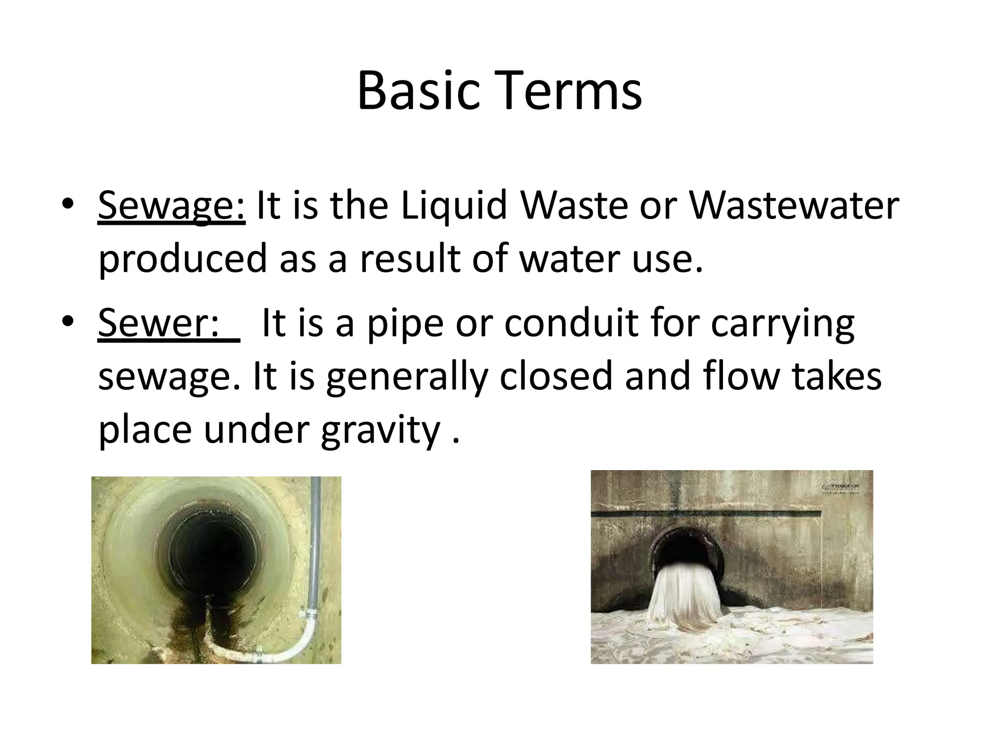
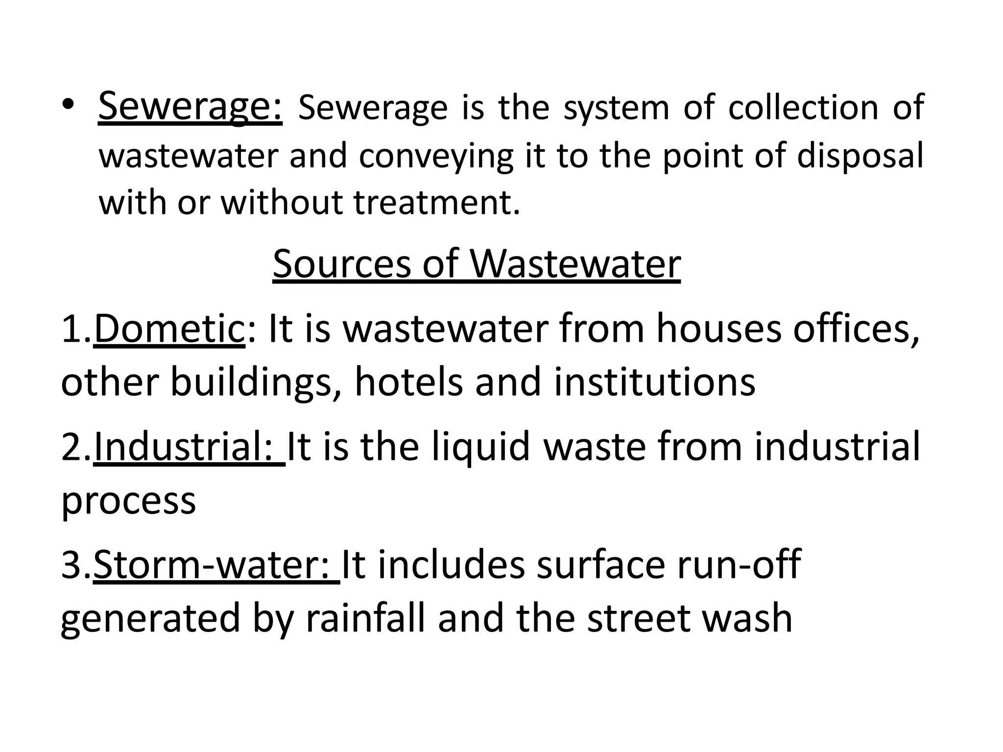
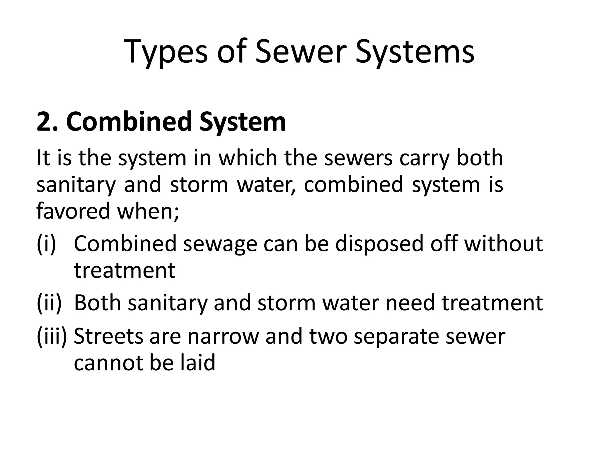
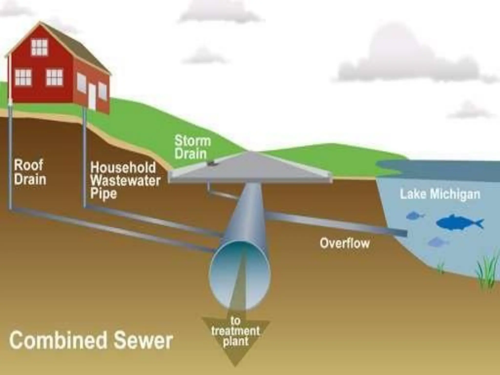
This document discusses the design of wastewater collection and disposal systems, covering essential terms, types of sewers, and components of wastewater engineering. It outlines various wastewater sources, the functioning of sewage pumps, and the characteristics of different sewer system types including combined and separated systems. Additionally, it addresses design considerations, flow variations, and the operational challenges associated with sewage pumping stations.


![Design of W.W. Collection System
Design criteria:
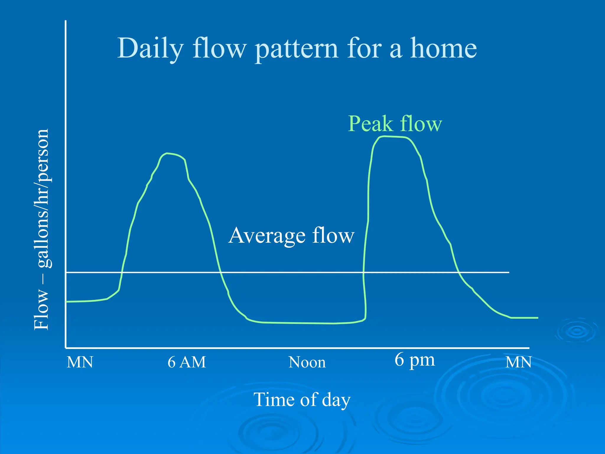
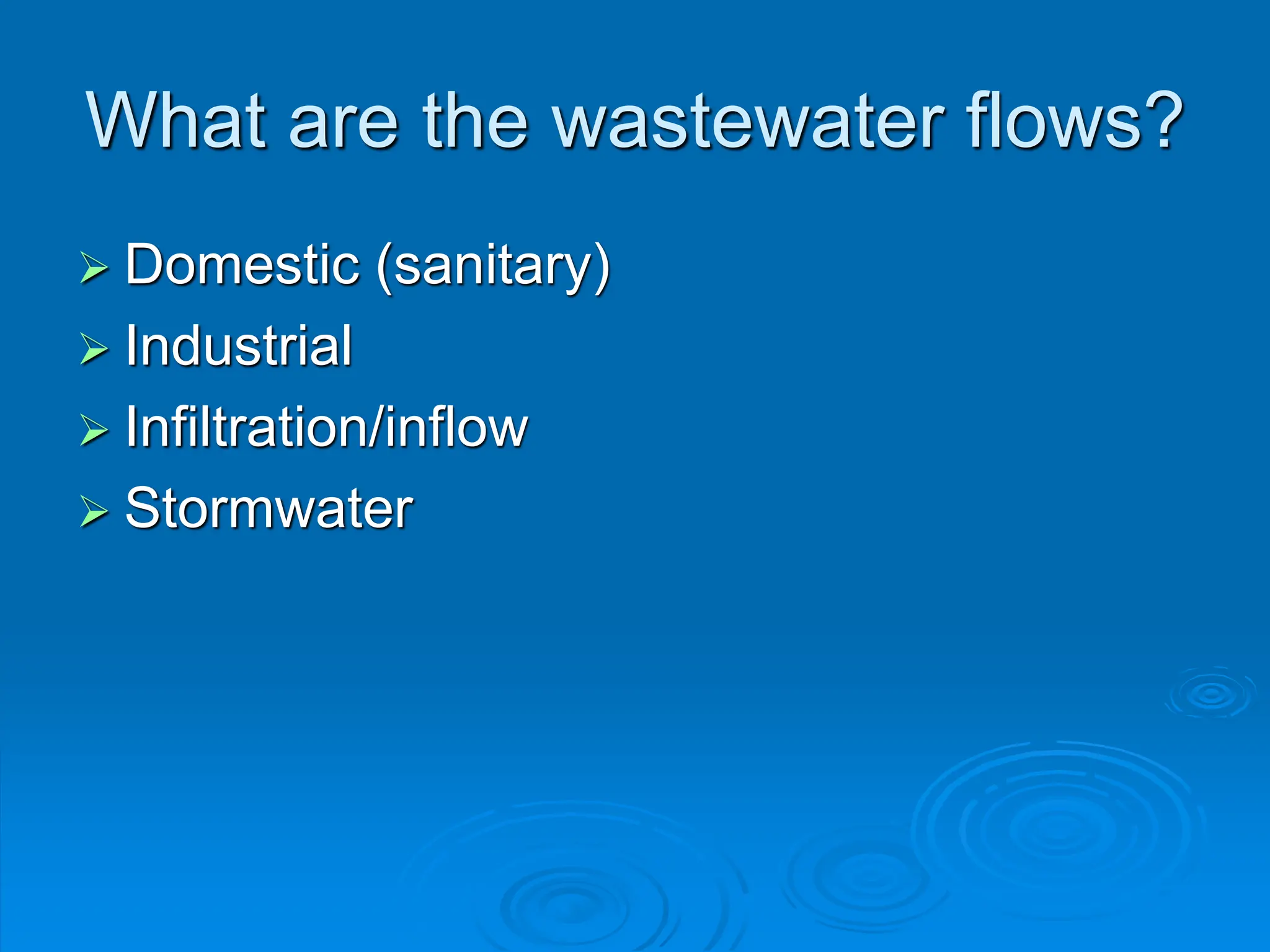
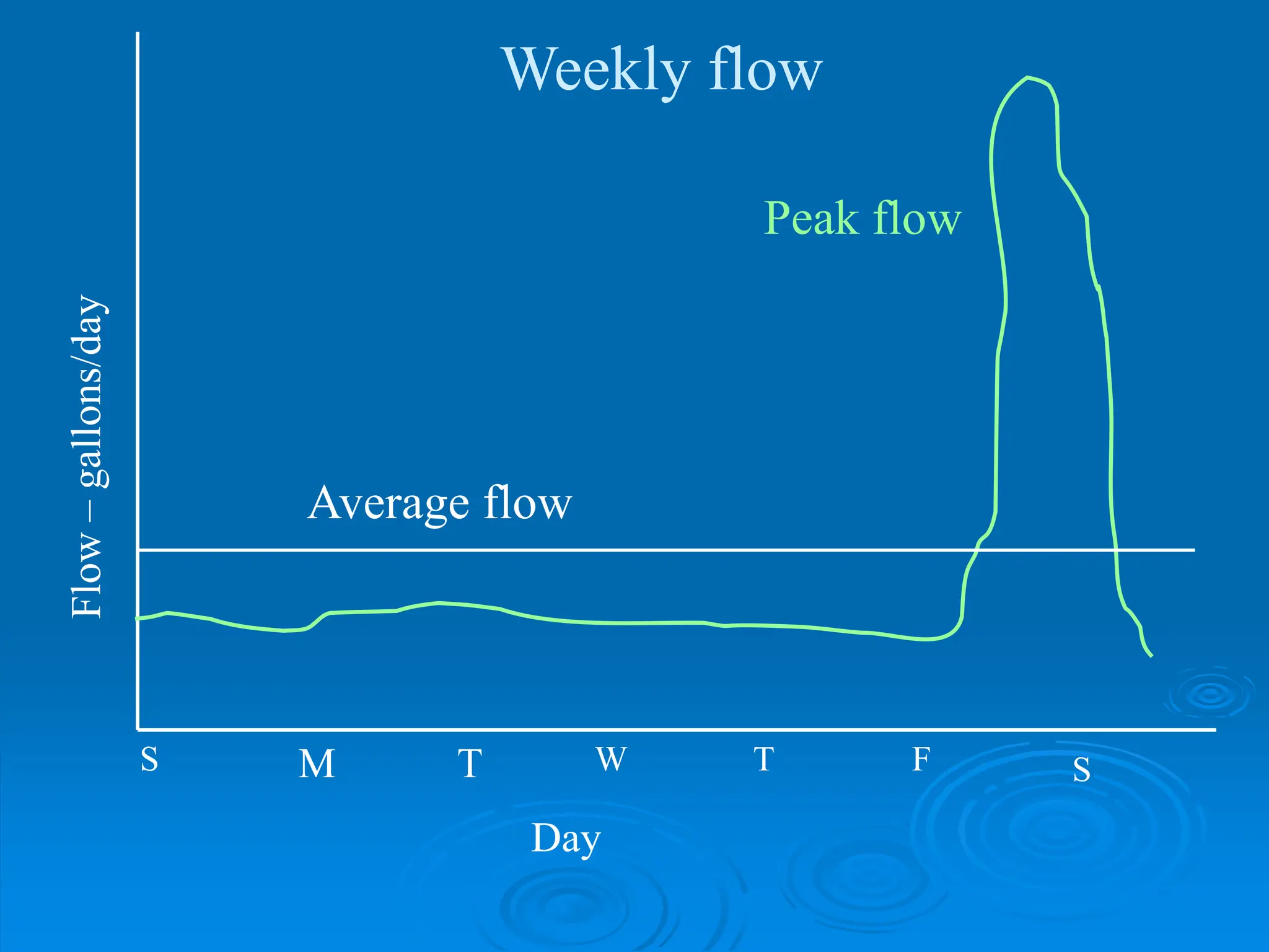
Waste water flow: Flow varies according to:
The season (monthly variations)
Weather conditions
Week of the month , day of the week, time of the day.
Estimation of the design flow Qdes: Data needed:
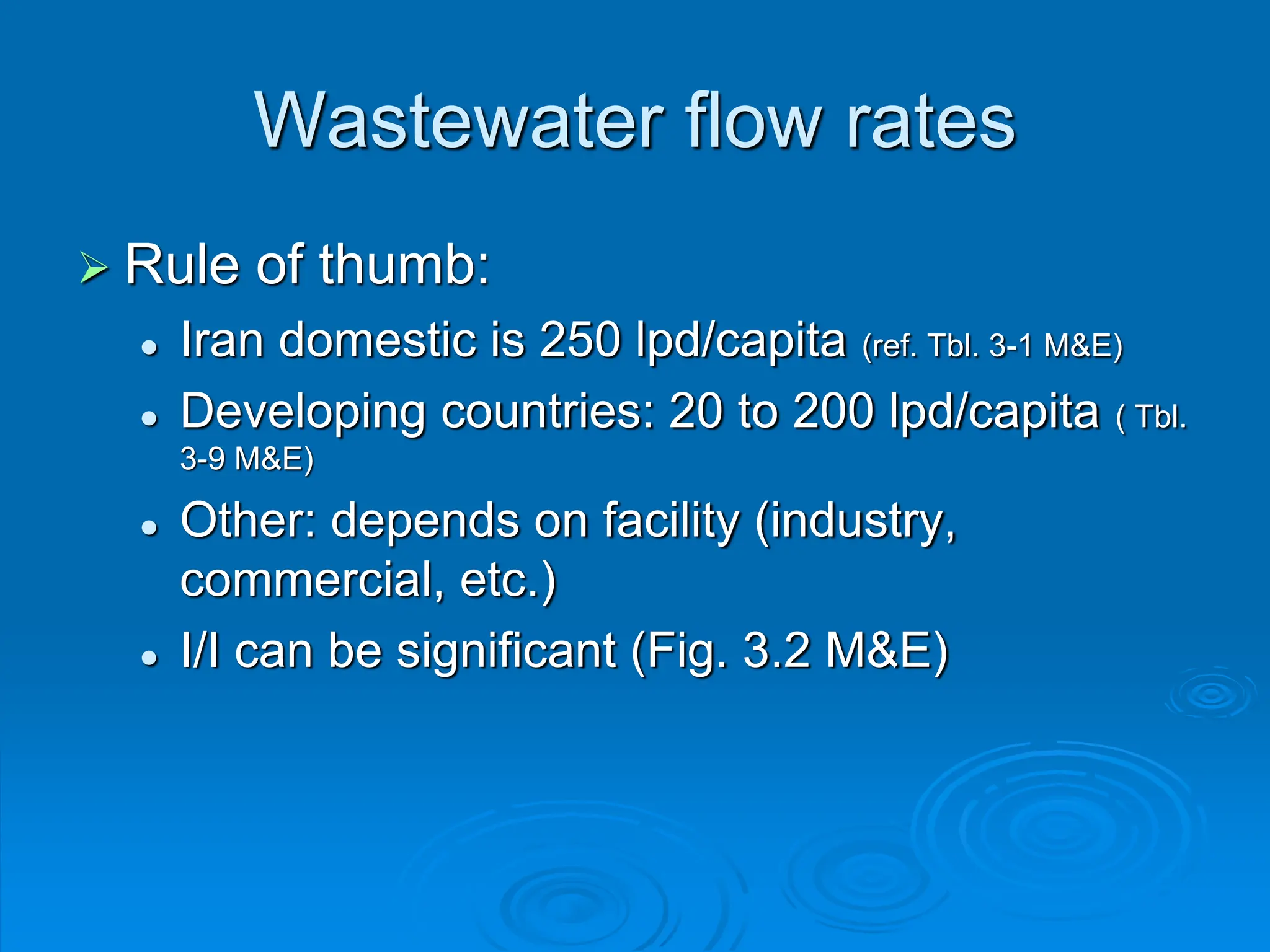
Average daily water consumption per capita for domestic areas (L/c/d), (Qavg).
Average daily water consumption per capita for institution ( school, offices, ….etc. ), (Qavg).
Average daily water consumption for commercial and industrial areas.
Infiltration, inflow:
Qinfil is taken as [24-95 m3/day/km] or [0.5 m3/day/diamwter (cm)], take the bigger value of
the two.
Qinflo is taken as 0.2-30 [m3/ha/day]. ( hectare = 10,000 m2 )
Qdes = Qmax + QI/I ( if found)
QI/I = Qinfil + Qinflo
Qmax = [0.80* Qavg] * Pƒ ( 0.8 > 80% return from water supply).
This equation is for domestic users only. Qmax for institutions, commercial activities, and
industries are calculated according to the type of industry, and cannot be calculated from
this equation. Each industry has its specific average wastewater production and peaking
factor that can be taken from published references or from the records of these industries
or institutions.](https://image.slidesharecdn.com/treslidesunitvwastewatercollectionanddisposalsystems-240828183544-375a77be/75/TRE-Slides-Unit-V_Wastewater-collection-and-disposal-systems-pdf-142-2048.jpg)

![- Pƒ : peak factor for domestic wastewater can be calculated
from one of the following formulas :
P
f
P
4
14
1 , ( P: population in thousands)
Or 167
.
0
5
P
f
P
The minimum domestic wastewater flow (Qmin) is necessary to check
for the minimum velocity in the sanitary sewers, it is estimated from
the following formula:
W
avg
Q
P
Q
*
6
1
2
.
0
min
A typical value of
W
avg
Q
Q
3
1
min
Note: [Qavg]w = 0.8 Qavg , which is
the average domestic wastewater
production , while Qavg is the
average water consumption.](https://image.slidesharecdn.com/treslidesunitvwastewatercollectionanddisposalsystems-240828183544-375a77be/75/TRE-Slides-Unit-V_Wastewater-collection-and-disposal-systems-pdf-144-2048.jpg)
![Example
A gravity pipe serving a community of 50,000 inh. The length of the pipe
is 200 m, and the average water consumption is 120 L/c/d. Use an
infiltration rate of 30 m3
/day.km, and a wastewater production rate of
80% of the water supply. Neglect the inflow for this example. Calculate
Qdes and Qmin.
a. Calculate the average domestic WW flow:
[Qavg]w = 0.8 Qavg = 0.80 * 120 L/c/d * 50,000 capita* 10-3
= 4800 m3
/d
b. Calculate the peak factor:
P
f
P
4
14
1 = 26
.
2
50
4
14
1
Solution](https://image.slidesharecdn.com/treslidesunitvwastewatercollectionanddisposalsystems-240828183544-375a77be/75/TRE-Slides-Unit-V_Wastewater-collection-and-disposal-systems-pdf-145-2048.jpg)
![a. Calculate the maximum wastewater flow:
Qmax = [Qavg]w * Pƒ = 2.26 * 4800 = 10848 m3
/d
b. Calculate the minimum wastewater flow:
W
avg
Q
P
Q
*
6
1
2
.
0
min 1845
4800
*
6
1
)
50
(
2
.
0
m3
/d
c. Calculate the infiltration flow:
Qinfil = 30 *0.20 = 6 m3
/d
d. Calculate the design flow:
Qdes = Qmax + QI/I = 10848 + 6 = 10854 m3
/d](https://image.slidesharecdn.com/treslidesunitvwastewatercollectionanddisposalsystems-240828183544-375a77be/75/TRE-Slides-Unit-V_Wastewater-collection-and-disposal-systems-pdf-146-2048.jpg)


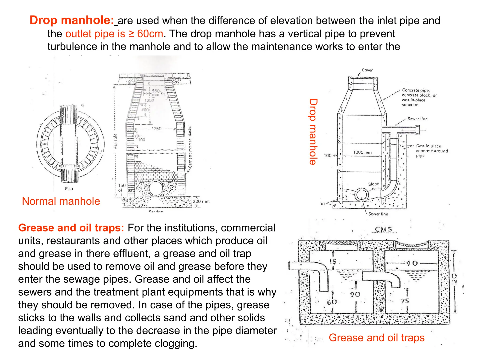
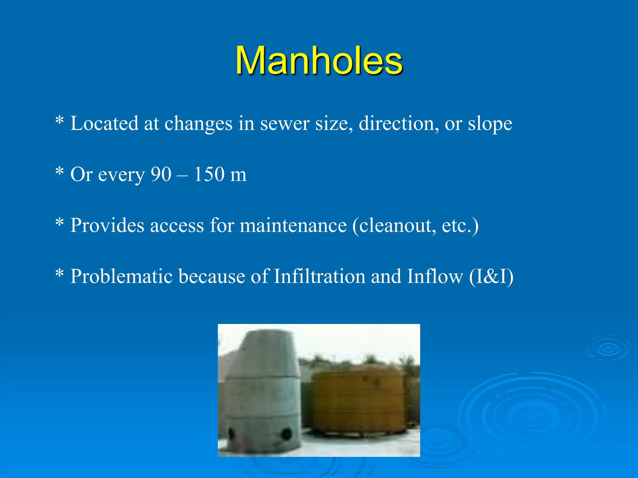
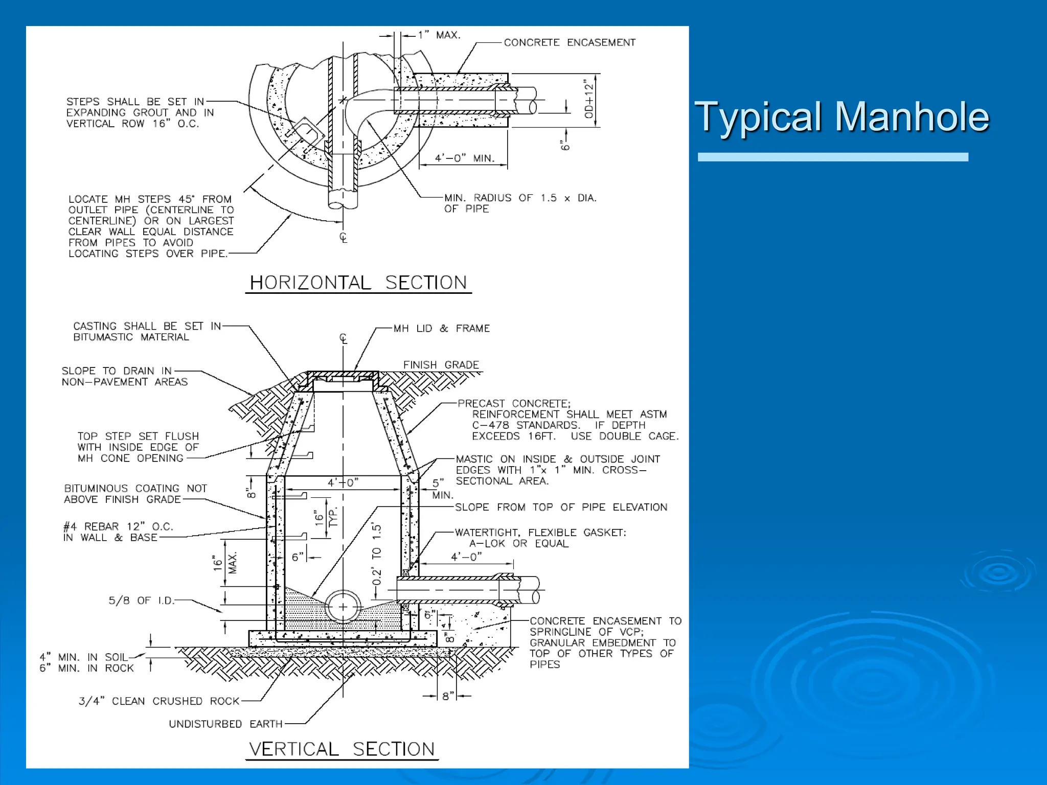
![Manhole dimensions
The diameter of the manhole or its side's dimensions depends on the depth of excavation.
The following table gives their relation.
Depth of manhole Manhole dimensions
0.60 x 0.60 m [Square]
Depth ≤ 0.90 m
Φ 0.60 m [ Circular]
1 . 0 0 x 1 . 0 0 [ S q u a r e ]
Φ 1 . 0 0 m [ C i r c u l a r ]
1 . 5 0 - 2 . 0 0 m
0 . 8 0 x 1 . 2 0 m [ R e c t a n g u l a r ]
≥ 2 . 0 0 m Φ 1 . 5 0 m [ C i r c u l a r ]
• The cover of the manhole should be strong enough to withstand the loads of traffic.
• It is usually made of cast iron to carry a minimum concentrated load of 25 ton.
• The manhole should be supplied with steps to allow for maintenance access.
• The floor of the manhole should be lined with cement mortar which is called
benching.](https://image.slidesharecdn.com/treslidesunitvwastewatercollectionanddisposalsystems-240828183544-375a77be/75/TRE-Slides-Unit-V_Wastewater-collection-and-disposal-systems-pdf-154-2048.jpg)