Downloaded 111 times

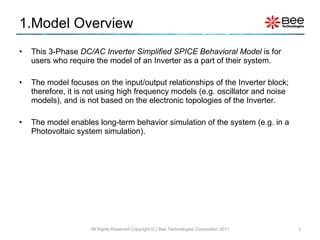
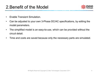

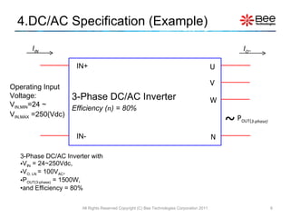
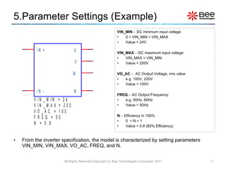
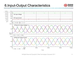


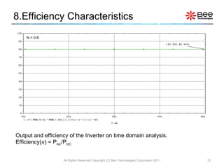
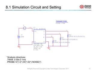


This document describes a simplified SPICE behavioral model for a 3-phase DC/AC inverter. The model allows for transient simulation of the inverter's input-output characteristics without detailed circuitry. It is parameterized based on the inverter's specifications, such as voltage and efficiency ratings. Simulation examples are provided to demonstrate the inverter's output voltage, current, efficiency, and behavior at minimum input voltage.


![[Daniel_W._Hart]_Power_Electronic(www.knowing.ir)-1 (1).pdf](https://cdn.slidesharecdn.com/ss_thumbnails/danielw-231119080747-193d829a-thumbnail.jpg?width=640&height=640&fit=bounds)


![[9_CV] FCS-Model Predictive Control of Induction Motors feed by MultilLevel C...](https://cdn.slidesharecdn.com/ss_thumbnails/9cvfcs-modelpredictivecontrolofinductionmotorsfeedbymultillevelcasadedh-bridgeinverter-190418083950-thumbnail.jpg?width=640&height=640&fit=bounds)