Download to read offline
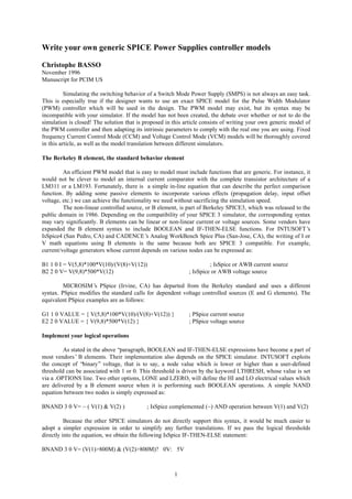
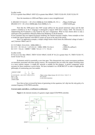
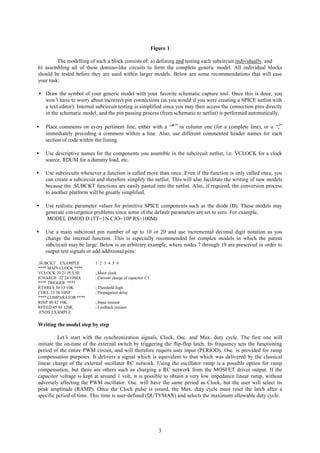
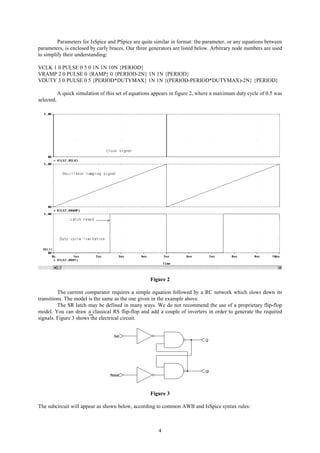
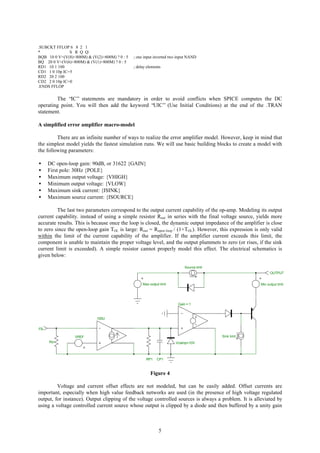

This document discusses writing generic SPICE models for power supply controllers. It begins by explaining that exact SPICE models may not exist or be compatible with the user's simulator. The solution is to write a generic model and adapt it to the specific controller. It then provides examples of using behavioral (B) elements to model nonlinear functions like comparators and logic gates in different simulators like ISspice, PSpice, and AWB. Guidelines are given for writing models step-by-step, including using subcircuits and descriptive names. Finally, it discusses modeling a constant frequency current mode PWM controller as an example application.


![74676371-Coagulation-and-Flocculation[1].ppt](https://cdn.slidesharecdn.com/ss_thumbnails/74676371-coagulation-and-flocculation1-260116154109-a3cbf55e-thumbnail.jpg?width=640&height=640&fit=bounds)


