Download as PDF, PPTX
![3. Parameter Settings
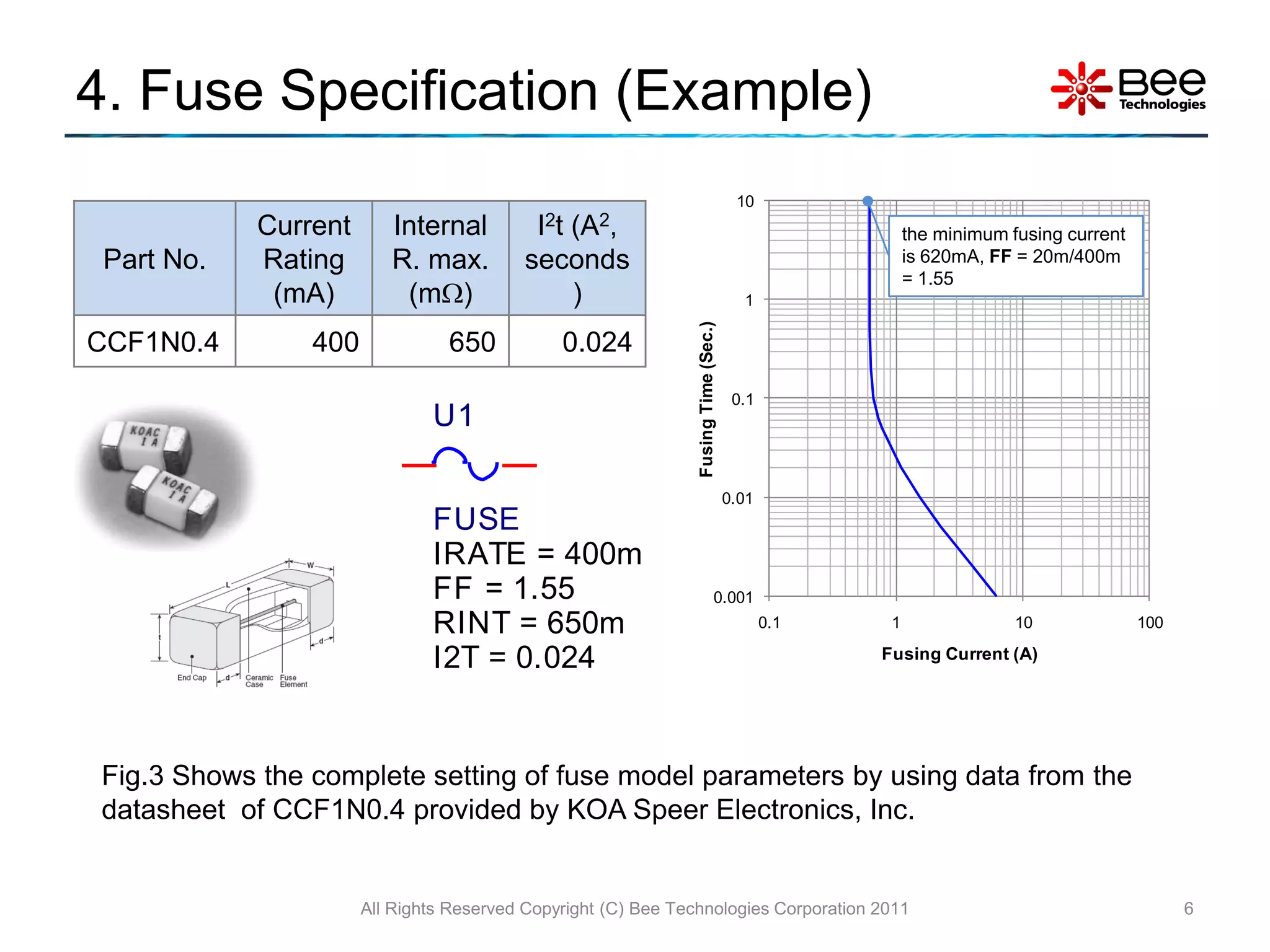
• From the fuse specification, the model is characterized by setting parameters Irate, FF,
Rint and I2t.
Model Parameters:
U1 Irate = the current rating of fuse [A]
FF = Fusing Factor, the ratio of the
minimum fusing current (the current
FUSE that fuse start to heat up) to Irate.
(e.g. Irate =400mA and the minimum
IRATE = 400m fusing current is 620mA then FF =
FF = 1.55 620m/400m = 1.55)
RINT = 650m Rint = internal resistance of fuse
I2T = 0.024
I2t = Normal Melting value [A2, seconds]
Fig.2 Fuse model with default parameters
All Rights Reserved Copyright (C) Bee Technologies Corporation 2011 5](https://image.slidesharecdn.com/simplemodeloffuseusingpspice-110801021921-phpapp01/75/Simple-model-of-Fuse-PSpice-5-2048.jpg)
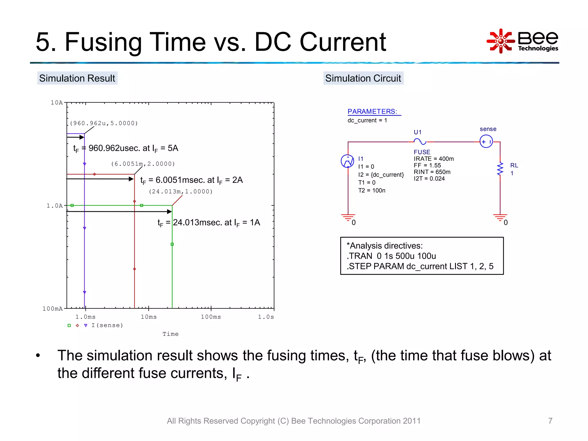
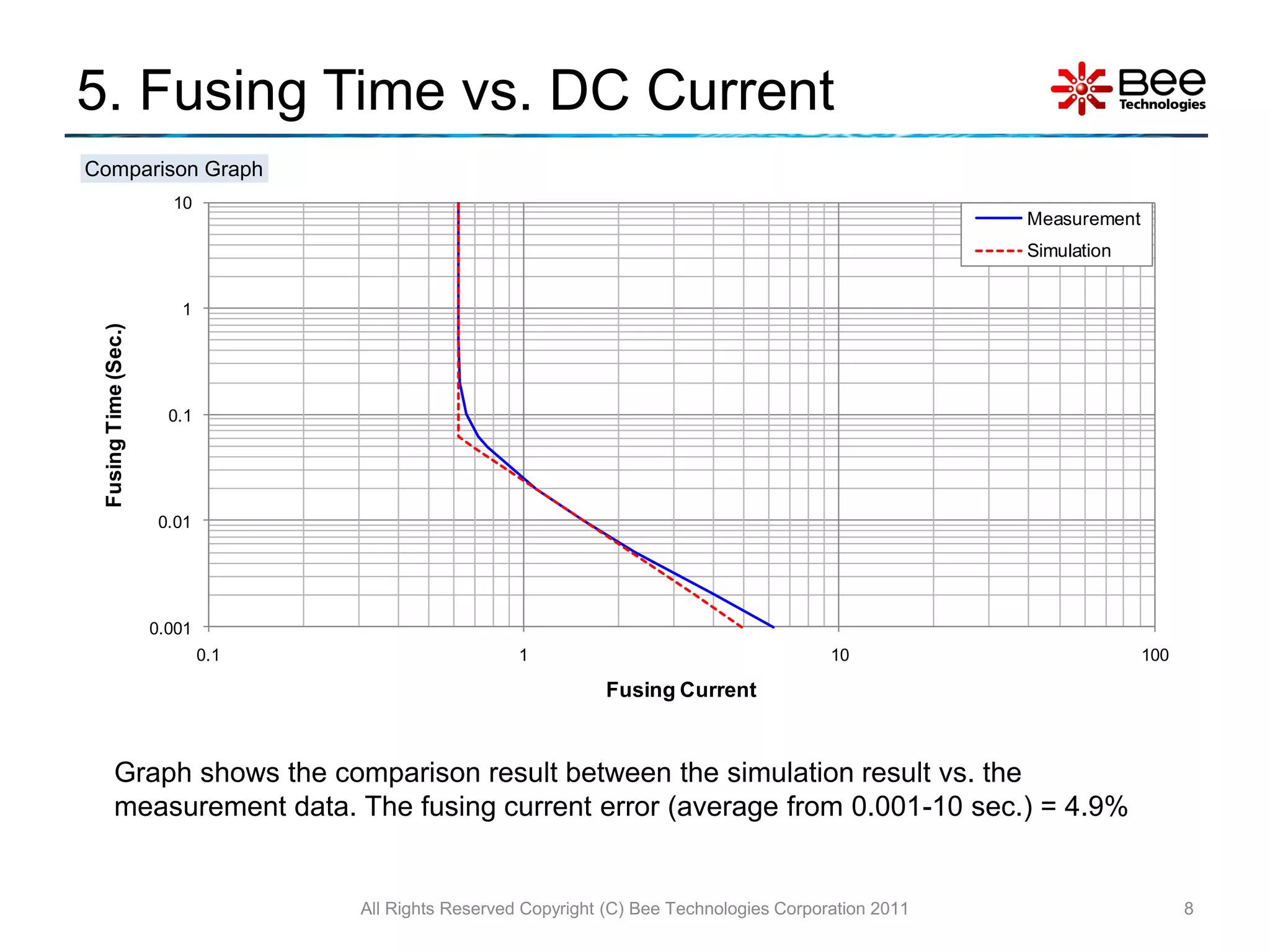
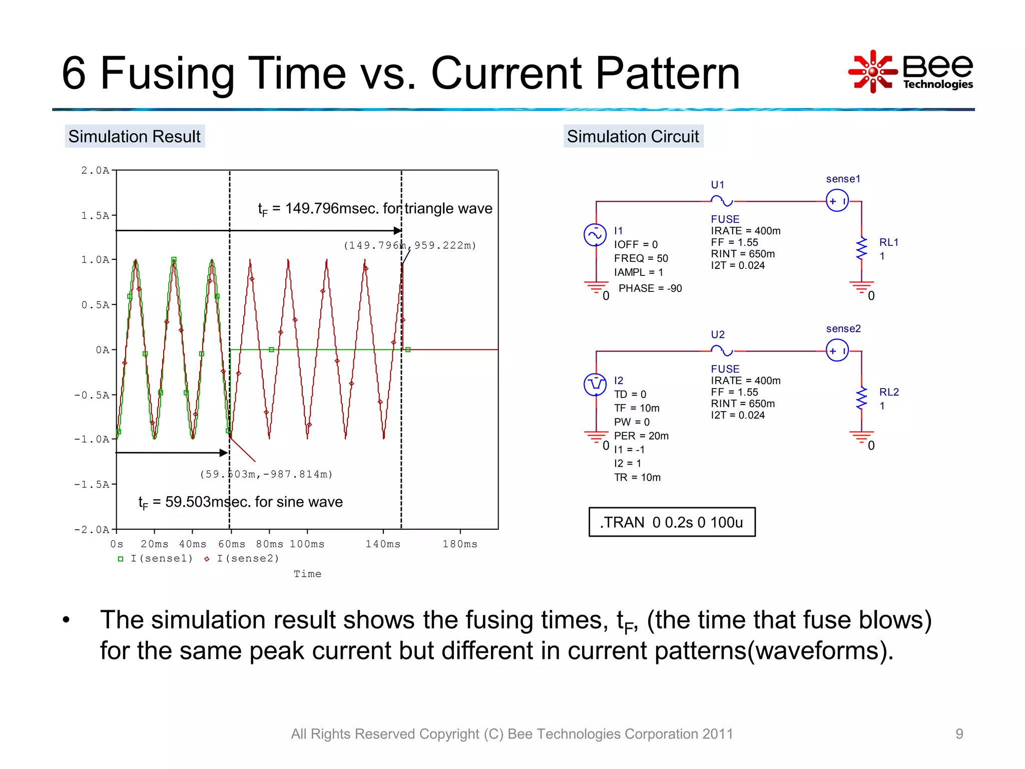
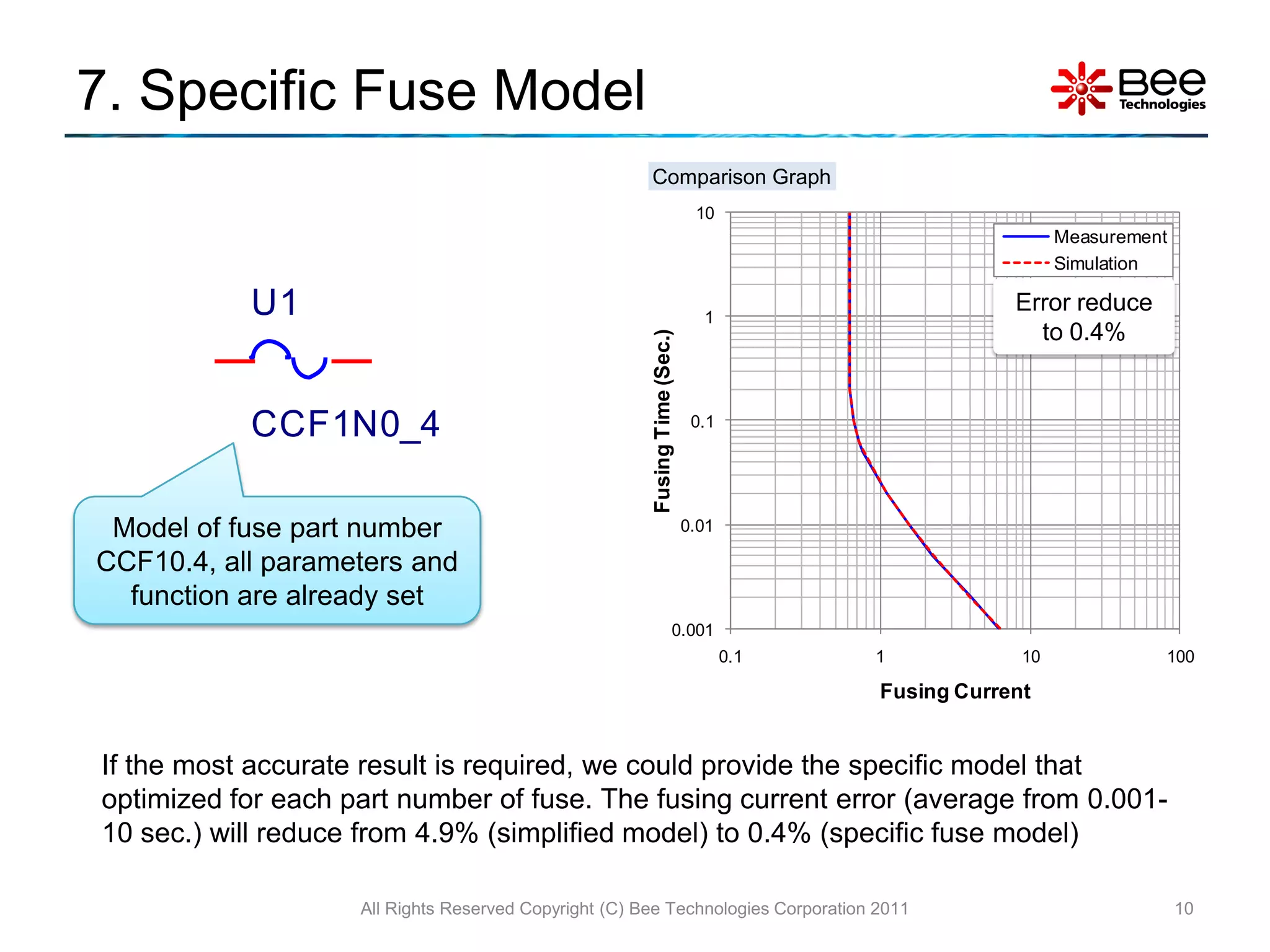

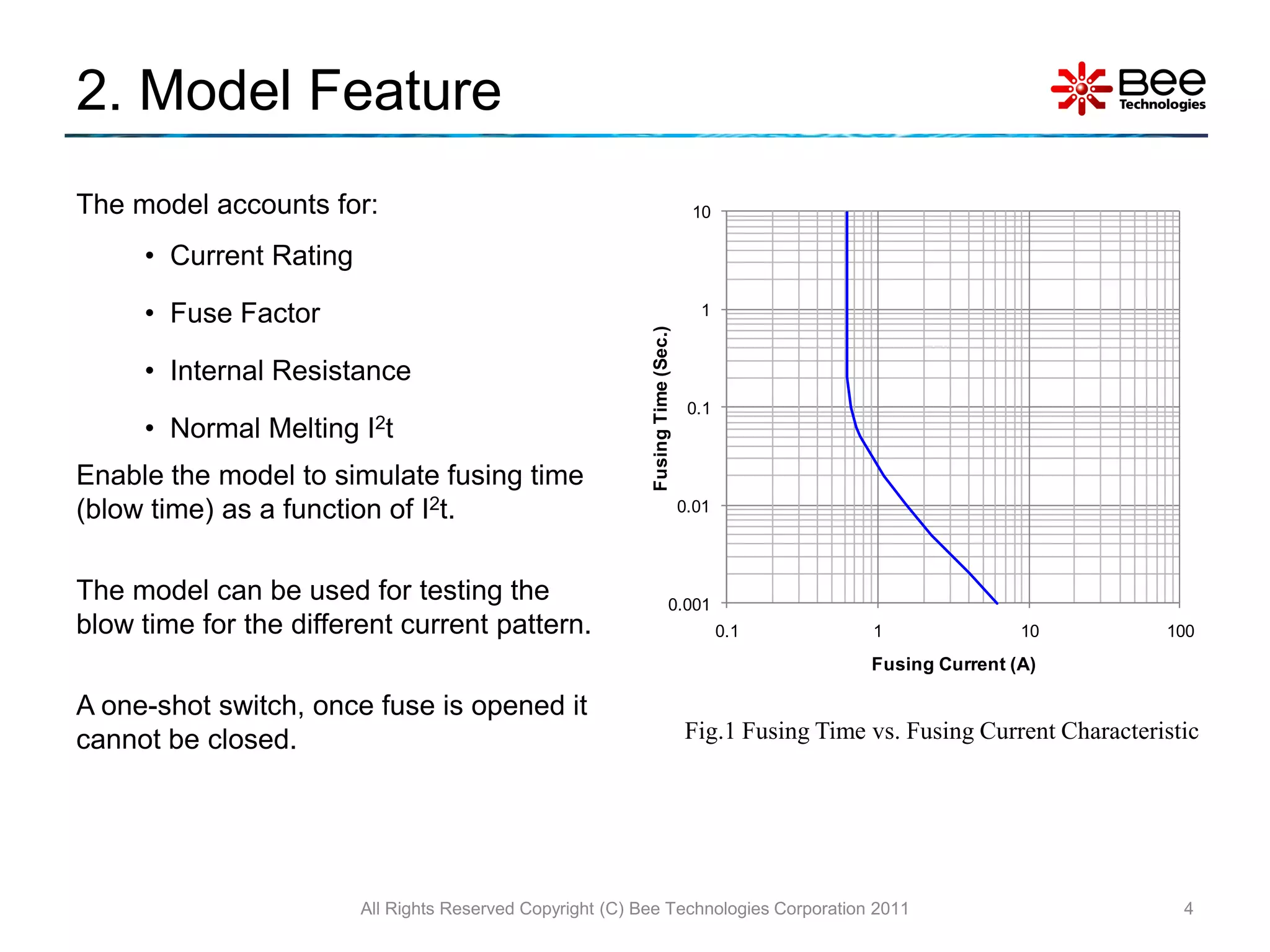
This document describes a simplified SPICE behavioral model for simulating fuse behavior. The model allows users to set parameters like current rating, fusing factor, internal resistance, and melting value based on datasheet specifications. Simulation results show fusing time varies with DC current level and different current waveforms based on I2t heating effects. A specific fuse model tailored for a part provides more accurate fusing time predictions than the general model.