Downloaded 101 times
![3-Phase AC Motor Model
Simplifies SPICE Behavior Model
[PSpice Model Version]
U1
1 AC_MOTOR
2
3
M 4 LL = 105U
N0 RLL = 0.0125
KE = 0.02
KT = 1.6
LOAD = 140
Bee Technologies Inc.
All Rights Reserved Copyright (C) Bee Technologies Inc. 2012 1](https://image.slidesharecdn.com/3-phaseacmotormodelpsspice-120913222822-phpapp02/85/3-Phase-AC-Motor-Model-PSpice-Model-1-320.jpg)
![3-Phase AC Motor Model
Simplifies SPICE Behavior Model
[PSpice Model Version]
U1
1 AC_MOTOR
2
3
M 4 LL = 105U
N0 RLL = 0.0125
KE = 0.02
KT = 1.6
LOAD = 140
Bee Technologies Inc.
All Rights Reserved Copyright (C) Bee Technologies Inc. 2012 1](https://image.slidesharecdn.com/3-phaseacmotormodelpsspice-120913222822-phpapp02/75/3-Phase-AC-Motor-Model-PSpice-Model-1-2048.jpg)
![4) Parameters Settings
Model Parameters:
LOAD : Load current each phase of motor [Arms]
U1 – e.g. LL = 125Arms, 140Arms, or 400Arms
AC_Motor
1
LL : Phase inductance [H]
LL = 105U
– e.g. LL = 10mH, 100mH, or 1H
2
3
M 4 RLL = 0.0125
N0 KE = 0.02
KT = 1.6 RLL : Phase resistance (Phase-to-phase) [Ω]
LOAD = 140 – e.g. RLL = 10mΩ, 100mΩ, or 1Ω
KE : Back-EMF constant [V/RPM]
– e.g. KE= 0.01, 0.05, or 0.1
Fig. 4 Symbol of 3-Phase Induction Motor KT : Torque constant [Lb-in/A]
– e.g. KT= 0.1, 0.5, or 1
1 Pound Inch equals 0.11 Nm
• From the 3-Phase Induction Motor specification, the model is characterized by setting parameters
LL, RLL, KE, KT and LOAD.
All Rights Reserved Copyright (C) Bee Technologies Inc. 2012 5](https://image.slidesharecdn.com/3-phaseacmotormodelpsspice-120913222822-phpapp02/85/3-Phase-AC-Motor-Model-PSpice-Model-5-320.jpg)

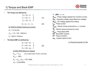
This document describes a 3-phase AC motor model for simulation in SPICE. [1] The model simplifies the motor's behavior using equivalent circuits to represent the torque, back-EMF, and mechanical parts of the motor. Torque and back-EMF are defined based on phase currents and angular speed. [2] Key parameters like phase inductance, resistance, back-EMF constant, torque constant, and load current can be set to characterize different motors. [3] The complete equivalent circuit model combines the frequency response, back-EMF generation, and mechanical torque production to simulate 3-phase motor behavior in SPICE simulations.


