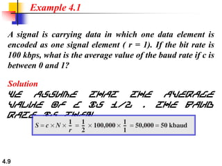
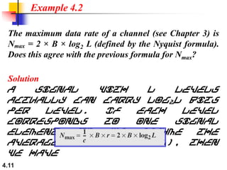
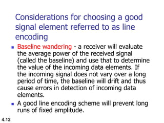
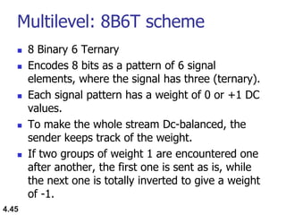
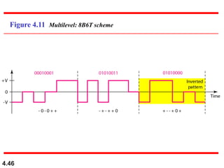
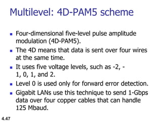
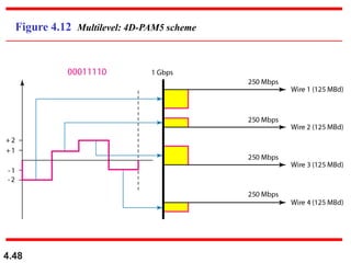
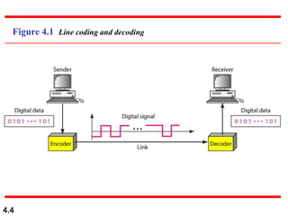
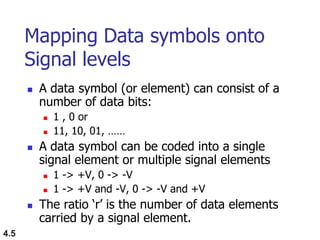
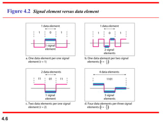
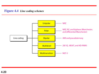
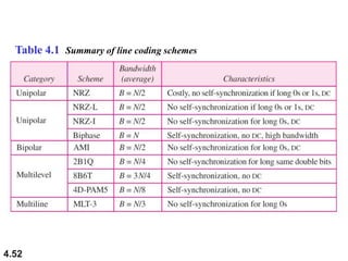
SlideShare a Scribd company logo
4.1
Chapter 4
Digital Transmission
Copyright © The McGraw-Hill Companies, Inc. Permission required for reproduction or display.
4.2
4-1 DIGITAL-TO-DIGITAL CO
In this section, we see how we can represent digital
data by using digital signals. The conversion involves
three techniques: line coding, block coding, and
scrambling. Line coding is always needed; block
coding and scrambling may or may not be needed.
 Line Coding
 Line Coding Schemes
 Block Coding
 Scrambling
Topics discussed in this section:
4.3
Line Coding
 Converting a string of 1‟s and 0‟s
(digital data) into a sequence of signals
that denote the 1‟s and 0‟s.
 For example a high voltage level (+V)
could represent a “1” and a low voltage
level (0 or -V) could represent a “0”.
4.4
Figure 4.1 Line coding and decoding
4.5
Mapping Data symbols onto
Signal levels
 A data symbol (or element) can consist of a
number of data bits:
 1 , 0 or
 11, 10, 01, ……
 A data symbol can be coded into a single
signal element or multiple signal elements
 1 -> +V, 0 -> -V
 1 -> +V and -V, 0 -> -V and +V
 The ratio „r‟ is the number of data elements
carried by a signal element.
4.6
Figure 4.2 Signal element versus data element
4.7
Relationship between data
rate and signal rate
 The data rate defines the number of bits sent
per sec - bps. It is often referred to the bit
rate.
 The signal rate is the number of signal
elements sent in a second and is measured in
bauds. It is also referred to as the modulation
rate.
 Goal is to increase the data rate whilst
reducing the baud rate.
4.8
Data rate and Baud rate
 The baud or signal rate can be
expressed as:
S = c x N x 1/r bauds
where N is data rate
c is the case factor (worst, best & avg.)
r is the ratio between data element &
signal element
4.9
A signal is carrying data in which one data element is
encoded as one signal element ( r = 1). If the bit rate is
100 kbps, what is the average value of the baud rate if c is
between 0 and 1?
Solution
We assume that the average
value of c is 1/2 . The baud
rate is then
Example 4.1
4.10
Although the actual bandwidth of a
digital signal is infinite, the effective
bandwidth is finite.
Note
4.11
The maximum data rate of a channel (see Chapter 3) is
Nmax = 2 × B × log2 L (defined by the Nyquist formula).
Does this agree with the previous formula for Nmax?
Solution
A signal with L levels
actually can carry log2L bits
per level. If each level
corresponds to one signal
element and we assume the
average case (c = 1/2), then
we have
Example 4.2
4.12
Considerations for choosing a good
signal element referred to as line
encoding
 Baseline wandering - a receiver will evaluate
the average power of the received signal
(called the baseline) and use that to determine
the value of the incoming data elements. If
the incoming signal does not vary over a long
period of time, the baseline will drift and thus
cause errors in detection of incoming data
elements.
 A good line encoding scheme will prevent long
runs of fixed amplitude.
4.13
Line encoding characteristics
 DC components - when the voltage
level remains constant for long periods
of time, there is an increase in the low
frequencies of the signal. Most channels
are bandpass and may not support the
low frequencies.
 This will require the removal of the dc
component of a transmitted signal.
4.14
Line encoding characteristics
 Self synchronization - the clocks at the
sender and the receiver must have the
same bit interval.
 If the receiver clock is faster or slower it
will misinterpret the incoming bit
stream.
4.15
Figure 4.3 Effect of lack of synchronization
4.16
In a digital transmission, the receiver clock is 0.1 percent
faster than the sender clock. How many extra bits per
second does the receiver receive if the data rate is
1 kbps? How many if the data rate is 1 Mbps?
Solution
At 1 kbps, the receiver
receives 1001 bps instead of
1000 bps.
Example 4.3
At 1 Mbps, the receiver receives 1,001,000 bps instead of
1,000,000 bps.
4.17
Line encoding characteristics
 Built-in Error detection - errors occur
during transmission due to line
impairments.
 Some codes are constructed such that
when an error occurs it can be
detected. For example: a particular
signal transition is not part of the code.
When it occurs, the receiver will know
that a symbol error has occurred.
4.18
Line encoding characteristics
 Immunity to Noise and Interference -
there are line encoding techniques that
make the transmitted signal “immune”
to noise and interference.
 This means that the signal cannot be
corrupted, it is stronger than error
detection.
4.19
Line encoding characteristics
 Complexity - the more robust and
resilient the code, the more complex it
is to implement and the price is often
paid in baud rate or required
bandwidth.
4.20
Figure 4.4 Line coding schemes
4.21
Unipolar
 All signal levels are on one side of the time
axis - either above or below
 NRZ - Non Return to Zero scheme is an
example of this code. The signal level does
not return to zero during a symbol
transmission.
 Scheme is prone to baseline wandering and
DC components. It has no synchronization or
any error detection. It is simple but costly in
power consumption.
4.22
Figure 4.5 Unipolar NRZ scheme
4.23
Polar - NRZ
 The voltages are on both sides of the time
axis.
 Polar NRZ scheme can be implemented with
two voltages. E.g. +V for 1 and -V for 0.
 There are two versions:
 NRZ - Level (NRZ-L) - positive voltage for one
symbol and negative for the other
 NRZ - Inversion (NRZ-I) - the change or lack of
change in polarity determines the value of a
symbol. E.g. a “1” symbol inverts the polarity a “0”
does not.
4.24
Figure 4.6 Polar NRZ-L and NRZ-I schemes
4.25
In NRZ-L the level of the voltage
determines the value of the bit.
In NRZ-I the inversion
or the lack of inversion
determines the value of the bit.
Note
4.26
NRZ-L and NRZ-I both have an average
signal rate of N/2 Bd.
Note
4.27
NRZ-L and NRZ-I both have a DC
component problem and baseline
wandering, it is worse for NRZ-L. Both
have no self synchronization &no error
detection. Both are relatively simple to
implement.
Note
4.28
A system is using NRZ-I to transfer 1-Mbps data. What
are the average signal rate and minimum bandwidth?
Solution
The average signal rate is S=
c x N x R = 1/2 x N x 1 = 500
kbaud. The minimum bandwidth
for this average baud rate is
Bmin = S = 500 kHz.
Note c = 1/2 for the avg.
Example 4.4
4.29
Polar - RZ
 The Return to Zero (RZ) scheme uses three
voltage values. +, 0, -.
 Each symbol has a transition in the middle.
Either from high to zero or from low to zero.
 This scheme has more signal transitions (two
per symbol) and therefore requires a wider
bandwidth.
 No DC components or baseline wandering.
 Self synchronization - transition indicates
symbol value.
 More complex as it uses three voltage level.
It has no error detection capability.
4.30
Figure 4.7 Polar RZ scheme
4.31
Polar - Biphase: Manchester and
Differential Manchester
 Manchester coding consists of combining the
NRZ-L and RZ schemes.
 Every symbol has a level transition in the middle:
from high to low or low to high. Uses only two
voltage levels.
 Differential Manchester coding consists of
combining the NRZ-I and RZ schemes.
 Every symbol has a level transition in the middle.
But the level at the beginning of the symbol is
determined by the symbol value. One symbol
causes a level change the other does not.
4.32
Figure 4.8 Polar biphase: Manchester and differential Manchester schemes
4.33
In Manchester and differential
Manchester encoding, the transition
at the middle of the bit is used for
synchronization.
Note
4.34
The minimum bandwidth of Manchester
and differential Manchester is 2 times
that of NRZ. The is no DC component
and no baseline wandering. None of
these codes has error detection.
Note
4.35
Bipolar - AMI and Pseudoternary
 Code uses 3 voltage levels: +, 0, -, to
represent the symbols (note not transitions to
zero as in RZ).
 Voltage level for one symbol is at “0” and the
other alternates between + & -.
 Bipolar Alternate Mark Inversion (AMI) - the
“0” symbol is represented by zero voltage
and the “1” symbol alternates between +V
and -V.
 Pseudoternary is the reverse of AMI.
4.36
Figure 4.9 Bipolar schemes: AMI and pseudoternary
4.37
Bipolar characteristics
 It is a better alternative to NRZ.
 Has no DC component or baseline
wandering.
 Has no self synchronization because
long runs of “0”s results in no signal
transitions.
 No error detection.
4.38
Multilevel Schemes
 In these schemes we increase the number of
data bits per symbol thereby increasing the
bit rate.
 Since we are dealing with binary data we only
have 2 types of data element a 1 or a 0.
 We can combine the 2 data elements into a
pattern of “m” elements to create “2m”
symbols.
 If we have L signal levels, we can use “n”
signal elements to create Ln signal elements.
4.39
Code characteristics
 Now we have 2m symbols and Ln signals.
 If 2m > Ln then we cannot represent the data
elements, we don‟t have enough signals.
 If 2m = Ln then we have an exact mapping of
one symbol on one signal.
 If 2m < Ln then we have more signals than
symbols and we can choose the signals that
are more distinct to represent the symbols
and therefore have better noise immunity and
error detection as some signals are not valid.
4.40
Representing Multilevel Codes
 We use the notation mBnL, where m is
the length of the binary pattern, B
represents binary data, n represents the
length of the signal pattern and L the
number of levels.
 L = B binary, L = T for 3 ternary, L = Q
for 4 quaternary.
4.41
In mBnL schemes, a pattern of m data
elements is encoded as a pattern of n
signal elements in which 2m ≤ Ln.
Note
2B1Q (2 Binary 1 Quaternary)
 data patterns of size 2 bits are encoded as
one signal element belonging to a four-level
signal
 data is sent two times faster than with NRZ-L
 receiver has to discern 4 different thresholds
 the scheme was intended to be used by the
ISDN DSL and SDSL applications.
4.42
4.43
Figure 4.10 Multilevel: 2B1Q scheme
4.44
Multilevel using multiple channels
 In some cases, we split the signal transmission
up and distribute it over several links.
 The separate segments are transmitted
simultaneously. This reduces the signalling
rate per link -> lower bandwidth.
 This requires all bits for a code to be stored.
 xD: means that we use „x‟ links
 YYYz: We use „z‟ levels of modulation where
YYY represents the type of modulation (e.g.
pulse ampl. mod. PAM).
 Codes are represented as: xD-YYYz
Multilevel: 8B6T scheme
 8 Binary 6 Ternary
 Encodes 8 bits as a pattern of 6 signal
elements, where the signal has three (ternary).
 Each signal pattern has a weight of 0 or +1 DC
values.
 To make the whole stream Dc-balanced, the
sender keeps track of the weight.
 If two groups of weight 1 are encountered one
after another, the first one is sent as is, while
the next one is totally inverted to give a weight
of -1.
4.45
4.46
Figure 4.11 Multilevel: 8B6T scheme
Multilevel: 4D-PAM5 scheme
 Four-dimensional five-level pulse amplitude
modulation (4D-PAM5).
 The 4D means that data is sent over four wires
at the same time.
 It uses five voltage levels, such as -2, -
1, 0, 1, and 2.
 Level 0 is used only for forward error detection.
 Gigabit LANs use this technique to send 1-Gbps
data over four copper cables that can handle
125 Mbaud.
4.47
4.48
Figure 4.12 Multilevel: 4D-PAM5 scheme
4.49
Multitransition Coding
 Because of synchronization requirements we force
transitions. This can result in very high bandwidth
requirements -> more transitions than are bits (e.g.
mid bit transition with inversion).
 Codes can be created that are differential at the bit
level forcing transitions at bit boundaries. This results
in a bandwidth requirement that is equivalent to the
bit rate.
 In some instances, the bandwidth requirement may
even be lower, due to repetitive patterns resulting in
a periodic signal.
MLT-3 scheme
 The multiline transmission, three level
(MLT-3) scheme uses three levels
(+v, 0, and - V) and three transition rules
to move between the levels.
 If the next bit is 0, there is no transition.
 If the next bit is 1 and the current level is not
0, the next level is 0.
 If the next bit is 1 and the current level is
0, the next level is the opposite of the last
nonzero level.
4.50
4.51
Figure 4.13 Multitransition: MLT-3 scheme
4.52
Table 4.1 Summary of line coding schemes
4.53
Block Coding
 For a code to be capable of error detection, we need
to add redundancy, i.e., extra bits to the data bits.
 Synchronization also requires redundancy -
transitions are important in the signal flow and must
occur frequently.
 Block coding is done in three steps:
division, substitution and combination.
 It is distinguished from multilevel coding by use of
the slash - xB/yB.
 The resulting bit stream prevents certain bit
combinations that when used with line encoding
would result in DC components or poor sync. quality.
4.54
Block coding is normally referred to as
mB/nB coding;
it replaces each m-bit group with an
n-bit group.
Note
4.55
Figure 4.14 Block coding concept
4.56
Figure 4.15 Using block coding 4B/5B with NRZ-I line coding scheme
 The five bit codes were selected so that there is no more
than one leading zero and no more than two trailing
zeros.
 When the code are strung together, there can be no
more than three consecutive zeros.
4.57
Table 4.2 4B/5B mapping codes
4.58
Figure 4.16 Substitution in 4B/5B block coding
4.59
Figure 4.17 8B/10B block encoding
 The 8B/10B encoding is similar to 4B/5B encoding except that a
group of 8 bits of data is substituted by a 10-bit code.
 It provides greater error detection capability than 4B/5B.
 The most five significant bits is fed to the 5B/6B encoder; the
least 3 significant bits is fed into a 3B/4B encoder.
4.60
More bits - better error detection
 The 8B10B block code adds more
redundant bits and can thereby choose
code words that would prevent a long
run of a voltage level that would cause
DC components.
4.61
Scrambling
 The best code is one that does not increase
the bandwidth for synchronization and has no
DC components.
 Scrambling is a technique used to create a
sequence of bits that has the required c/c‟s for
transmission - self clocking, no low
frequencies, no wide bandwidth.
 It is implemented at the same time as
encoding, the bit stream is created on the fly.
 It replaces „unfriendly‟ runs of bits with a
violation code that is easy to recognize and
removes the unfriendly c/c.
4.62
Figure 4.18 AMI used with scrambling
Bipolar 8-Zero Substitution (B8ZS)
 B8ZS works in a similar way to AMI by
changing poles for each binary 1.
 B8ZS attempts to tackle the problem with
synchronisation being lost when there is a
stream of binary 0s being sent by making
artificial signal changes.
 These signals are known as violations and
occur when eight consecutive 0s occur in
the bit stream.
4.63
4.64
For example: B8ZS substitutes eight
consecutive zeros with 000VB0VB.
The V stands for violation, it violates the
line encoding rule
B stands for bipolar, it implements the
bipolar line encoding rule
4.65
Figure 4.19 Two cases of B8ZS scrambling technique
High Density Bipolar of Order 3 (HDB3)
 The high density bipolar of order 3
(HDB3) code replaces any instance of 4
consecutive 0 bits with one of the patterns
"000V" or "B00V".
 The choice is made to ensure that
consecutive violations are of differing
polarity, i.e. separated by an odd number
of normal + or - marks.
4.66
4.67
HDB3 substitutes four consecutive
zeros with 000V or B00V depending
on the number of nonzero pulses after
the last substitution.
If # of non zero pulses is even the
substitution is B00V to make total # of
non zero pulse even.
If # of non zero pulses is odd the
substitution is 000V to make total # of
non zero pulses even.
HDB 3 coding of "0000"
4.68
Number of +/-
bits
since last V
Pattern
Polarity
of last Pulse
Coded
odd 000V
+ 000+
− 000−
even B00V
+ −00−
− +00+
4.69
Figure 4.20 Different situations in HDB3 scrambling technique

More Related Content

What's hot

Types of line coding
Types of line codingTypes of line coding
Types of line coding
ramalakshmi54
 
Ec 2401 wireless communication unit 4
Ec 2401 wireless communication   unit 4Ec 2401 wireless communication   unit 4
Ec 2401 wireless communication unit 4
JAIGANESH SEKAR
 
Line coding presentation
Line coding presentationLine coding presentation
Line coding presentation
Dibyendu Porey
 
Pulse Code Modulation (PCM)
Pulse Code Modulation (PCM)Pulse Code Modulation (PCM)
Pulse Code Modulation (PCM)
Arun c
 
Dc unit iv
Dc unit ivDc unit iv
Comparsion of M-Ary psk,fsk,qapsk.pptx
Comparsion of M-Ary psk,fsk,qapsk.pptxComparsion of M-Ary psk,fsk,qapsk.pptx
Comparsion of M-Ary psk,fsk,qapsk.pptx
keshav11845
 
Block diagram of digital communication
Block diagram of digital communicationBlock diagram of digital communication
Block diagram of digital communication
mpsrekha83
 
Digital Data, Digital Signal | Scrambling Techniques
Digital Data, Digital Signal | Scrambling TechniquesDigital Data, Digital Signal | Scrambling Techniques
Digital Data, Digital Signal | Scrambling Techniques
Biplap Bhattarai
 
Amplitude modulation
Amplitude modulationAmplitude modulation
Amplitude modulation
Syed Zaid Irshad
 
MICROPROCESSOR & MICROCONTROLLER 8086,8051 Notes
MICROPROCESSOR & MICROCONTROLLER 8086,8051 NotesMICROPROCESSOR & MICROCONTROLLER 8086,8051 Notes
MICROPROCESSOR & MICROCONTROLLER 8086,8051 Notes
Velalar College of Engineering and Technology
 
Transmission impairments(presentation)
Transmission impairments(presentation)Transmission impairments(presentation)
Transmission impairments(presentation)
Vivek Kumar
 
Wireless communication ppt by dinesh
Wireless communication ppt by dineshWireless communication ppt by dinesh
Wireless communication ppt by dinesh
DINESH TAMBE
 
M ary psk modulation
M ary psk modulationM ary psk modulation
M ary psk modulation
Ahmed Diaa
 
TDMA
TDMATDMA
Dsss final
Dsss finalDsss final
Dsss final
AJAL A J
 
Line coding
Line coding Line coding
Line coding
Ravindra Rathore
 

What's hot (20)

Types of line coding
Types of line codingTypes of line coding
Types of line coding
 
Ec 2401 wireless communication unit 4
Ec 2401 wireless communication   unit 4Ec 2401 wireless communication   unit 4
Ec 2401 wireless communication unit 4
 
Line coding presentation
Line coding presentationLine coding presentation
Line coding presentation
 
Pulse Code Modulation (PCM)
Pulse Code Modulation (PCM)Pulse Code Modulation (PCM)
Pulse Code Modulation (PCM)
 
Lecture 08
Lecture 08Lecture 08
Lecture 08
 
Dc unit iv
Dc unit ivDc unit iv
Dc unit iv
 
Comparsion of M-Ary psk,fsk,qapsk.pptx
Comparsion of M-Ary psk,fsk,qapsk.pptxComparsion of M-Ary psk,fsk,qapsk.pptx
Comparsion of M-Ary psk,fsk,qapsk.pptx
 
Convolution Codes
Convolution CodesConvolution Codes
Convolution Codes
 
Block diagram of digital communication
Block diagram of digital communicationBlock diagram of digital communication
Block diagram of digital communication
 
Digital Data, Digital Signal | Scrambling Techniques
Digital Data, Digital Signal | Scrambling TechniquesDigital Data, Digital Signal | Scrambling Techniques
Digital Data, Digital Signal | Scrambling Techniques
 
Amplitude modulation
Amplitude modulationAmplitude modulation
Amplitude modulation
 
MICROPROCESSOR & MICROCONTROLLER 8086,8051 Notes
MICROPROCESSOR & MICROCONTROLLER 8086,8051 NotesMICROPROCESSOR & MICROCONTROLLER 8086,8051 Notes
MICROPROCESSOR & MICROCONTROLLER 8086,8051 Notes
 
Transmission impairments(presentation)
Transmission impairments(presentation)Transmission impairments(presentation)
Transmission impairments(presentation)
 
Spread spectrum
Spread spectrumSpread spectrum
Spread spectrum
 
Wireless communication ppt by dinesh
Wireless communication ppt by dineshWireless communication ppt by dinesh
Wireless communication ppt by dinesh
 
M ary psk modulation
M ary psk modulationM ary psk modulation
M ary psk modulation
 
TDMA
TDMATDMA
TDMA
 
Ch4 digital transmission
Ch4 digital transmissionCh4 digital transmission
Ch4 digital transmission
 
Dsss final
Dsss finalDsss final
Dsss final
 
Line coding
Line coding Line coding
Line coding
 

Viewers also liked

1432.encoding concepts
1432.encoding concepts1432.encoding concepts
1432.encoding conceptstechbed
 
4 signal encodingtechniques
4 signal encodingtechniques4 signal encodingtechniques
4 signal encodingtechniquesHattori Sidek
 
Multiplexing
MultiplexingMultiplexing
Multiplexing
nimay1
 
Pulse amplitude modulation
Pulse amplitude modulationPulse amplitude modulation
Pulse amplitude modulationVishal kakade
 

Viewers also liked (8)

1432.encoding concepts
1432.encoding concepts1432.encoding concepts
1432.encoding concepts
 
digital layer
digital layerdigital layer
digital layer
 
Ppt1
Ppt1Ppt1
Ppt1
 
Azbuka
AzbukaAzbuka
Azbuka
 
4 signal encodingtechniques
4 signal encodingtechniques4 signal encodingtechniques
4 signal encodingtechniques
 
Multiplexing
MultiplexingMultiplexing
Multiplexing
 
Pulse amplitude modulation
Pulse amplitude modulationPulse amplitude modulation
Pulse amplitude modulation
 
Line coding
Line codingLine coding
Line coding
 

Similar to Data communications 4 1

line coding techniques, block coding and all type of coding
line coding techniques, block coding and all type of codingline coding techniques, block coding and all type of coding
line coding techniques, block coding and all type of coding
DrZMaryLivinsaProfEC
 
Data Communication And Networking - DIGITAL TRANSMISSION
Data Communication And Networking - DIGITAL TRANSMISSIONData Communication And Networking - DIGITAL TRANSMISSION
Data Communication And Networking - DIGITAL TRANSMISSION
Avijeet Negel
 
Ch4 1 v1
Ch4 1 v1Ch4 1 v1
Ch4 1 v1
bhagavanprasad
 
Ch4 Data communication and networking by neha g. kurale
Ch4 Data communication and networking by neha g. kuraleCh4 Data communication and networking by neha g. kurale
Ch4 Data communication and networking by neha g. kurale
Neha Kurale
 
Data Encoding in Data Communication.pptx
Data Encoding in  Data Communication.pptxData Encoding in  Data Communication.pptx
Data Encoding in Data Communication.pptx
zulhelmanz
 
Line coding Tec hniques.pptx
Line coding Tec                 hniques.pptxLine coding Tec                 hniques.pptx
Line coding Tec hniques.pptx
naveen088888
 
ch04-digital-transmission.ppt
ch04-digital-transmission.pptch04-digital-transmission.ppt
ch04-digital-transmission.ppt
CDSukte
 
Multi level multi transition
Multi level multi transitionMulti level multi transition
lec5_13.pptx
lec5_13.pptxlec5_13.pptx
lec5_13.pptx
ShakibAhmed52
 
Lecture notes eng - Line Coding New.ppt
Lecture notes eng  - Line Coding New.pptLecture notes eng  - Line Coding New.ppt
Lecture notes eng - Line Coding New.ppt
JumanneChiyanda
 
Dcn aasignment
Dcn aasignmentDcn aasignment
Line Coding.pptx
Line Coding.pptxLine Coding.pptx
Line Coding.pptx
vishal choudhary
 
Lec-12-DCN.pptx about digital transmission and conversions
Lec-12-DCN.pptx about digital transmission and conversionsLec-12-DCN.pptx about digital transmission and conversions
Lec-12-DCN.pptx about digital transmission and conversions
az577330
 
Chapter2-PhysicalLayer.ppt
Chapter2-PhysicalLayer.pptChapter2-PhysicalLayer.ppt
Chapter2-PhysicalLayer.ppt
faisalahmed441
 
digital-analog_22222222222222222222222.pdf
digital-analog_22222222222222222222222.pdfdigital-analog_22222222222222222222222.pdf
digital-analog_22222222222222222222222.pdf
KiranG731731
 
Lec_CodingSchemes.pptx
Lec_CodingSchemes.pptxLec_CodingSchemes.pptx
Lec_CodingSchemes.pptx
slayHoaqin
 
base-band_digital_data_transmission-Line coding - Copy.ppt
base-band_digital_data_transmission-Line coding - Copy.pptbase-band_digital_data_transmission-Line coding - Copy.ppt
base-band_digital_data_transmission-Line coding - Copy.ppt
AbyThomas54
 
Binary to digital encoding tbs 301
Binary to digital encoding tbs 301Binary to digital encoding tbs 301
Binary to digital encoding tbs 301
Bhupesh Rawat
 

Similar to Data communications 4 1 (20)

line coding techniques, block coding and all type of coding
line coding techniques, block coding and all type of codingline coding techniques, block coding and all type of coding
line coding techniques, block coding and all type of coding
 
Data Communication And Networking - DIGITAL TRANSMISSION
Data Communication And Networking - DIGITAL TRANSMISSIONData Communication And Networking - DIGITAL TRANSMISSION
Data Communication And Networking - DIGITAL TRANSMISSION
 
Ch4 1 v1
Ch4 1 v1Ch4 1 v1
Ch4 1 v1
 
Ch4 Data communication and networking by neha g. kurale
Ch4 Data communication and networking by neha g. kuraleCh4 Data communication and networking by neha g. kurale
Ch4 Data communication and networking by neha g. kurale
 
Data Encoding in Data Communication.pptx
Data Encoding in  Data Communication.pptxData Encoding in  Data Communication.pptx
Data Encoding in Data Communication.pptx
 
Line coding Tec hniques.pptx
Line coding Tec                 hniques.pptxLine coding Tec                 hniques.pptx
Line coding Tec hniques.pptx
 
ch04-digital-transmission.ppt
ch04-digital-transmission.pptch04-digital-transmission.ppt
ch04-digital-transmission.ppt
 
Multi level multi transition
Multi level multi transitionMulti level multi transition
Multi level multi transition
 
lec5_13.pptx
lec5_13.pptxlec5_13.pptx
lec5_13.pptx
 
Lecture notes eng - Line Coding New.ppt
Lecture notes eng  - Line Coding New.pptLecture notes eng  - Line Coding New.ppt
Lecture notes eng - Line Coding New.ppt
 
Dcn aasignment
Dcn aasignmentDcn aasignment
Dcn aasignment
 
Unit 4
Unit 4Unit 4
Unit 4
 
Ch04
Ch04Ch04
Ch04
 
Line Coding.pptx
Line Coding.pptxLine Coding.pptx
Line Coding.pptx
 
Lec-12-DCN.pptx about digital transmission and conversions
Lec-12-DCN.pptx about digital transmission and conversionsLec-12-DCN.pptx about digital transmission and conversions
Lec-12-DCN.pptx about digital transmission and conversions
 
Chapter2-PhysicalLayer.ppt
Chapter2-PhysicalLayer.pptChapter2-PhysicalLayer.ppt
Chapter2-PhysicalLayer.ppt
 
digital-analog_22222222222222222222222.pdf
digital-analog_22222222222222222222222.pdfdigital-analog_22222222222222222222222.pdf
digital-analog_22222222222222222222222.pdf
 
Lec_CodingSchemes.pptx
Lec_CodingSchemes.pptxLec_CodingSchemes.pptx
Lec_CodingSchemes.pptx
 
base-band_digital_data_transmission-Line coding - Copy.ppt
base-band_digital_data_transmission-Line coding - Copy.pptbase-band_digital_data_transmission-Line coding - Copy.ppt
base-band_digital_data_transmission-Line coding - Copy.ppt
 
Binary to digital encoding tbs 301
Binary to digital encoding tbs 301Binary to digital encoding tbs 301
Binary to digital encoding tbs 301
 

Recently uploaded

JMeter webinar - integration with InfluxDB and Grafana
JMeter webinar - integration with InfluxDB and GrafanaJMeter webinar - integration with InfluxDB and Grafana
JMeter webinar - integration with InfluxDB and Grafana
RTTS
 
Builder.ai Founder Sachin Dev Duggal's Strategic Approach to Create an Innova...
Builder.ai Founder Sachin Dev Duggal's Strategic Approach to Create an Innova...Builder.ai Founder Sachin Dev Duggal's Strategic Approach to Create an Innova...
Builder.ai Founder Sachin Dev Duggal's Strategic Approach to Create an Innova...
Ramesh Iyer
 
Software Delivery At the Speed of AI: Inflectra Invests In AI-Powered Quality
Software Delivery At the Speed of AI: Inflectra Invests In AI-Powered QualitySoftware Delivery At the Speed of AI: Inflectra Invests In AI-Powered Quality
Software Delivery At the Speed of AI: Inflectra Invests In AI-Powered Quality
Inflectra
 
Empowering NextGen Mobility via Large Action Model Infrastructure (LAMI): pav...
Empowering NextGen Mobility via Large Action Model Infrastructure (LAMI): pav...Empowering NextGen Mobility via Large Action Model Infrastructure (LAMI): pav...
Empowering NextGen Mobility via Large Action Model Infrastructure (LAMI): pav...
Thierry Lestable
 
Encryption in Microsoft 365 - ExpertsLive Netherlands 2024
Encryption in Microsoft 365 - ExpertsLive Netherlands 2024Encryption in Microsoft 365 - ExpertsLive Netherlands 2024
Encryption in Microsoft 365 - ExpertsLive Netherlands 2024
Albert Hoitingh
 
From Daily Decisions to Bottom Line: Connecting Product Work to Revenue by VP...
From Daily Decisions to Bottom Line: Connecting Product Work to Revenue by VP...From Daily Decisions to Bottom Line: Connecting Product Work to Revenue by VP...
From Daily Decisions to Bottom Line: Connecting Product Work to Revenue by VP...
Product School
 
Epistemic Interaction - tuning interfaces to provide information for AI support
Epistemic Interaction - tuning interfaces to provide information for AI supportEpistemic Interaction - tuning interfaces to provide information for AI support
Epistemic Interaction - tuning interfaces to provide information for AI support
Alan Dix
 
Smart TV Buyer Insights Survey 2024 by 91mobiles.pdf
Smart TV Buyer Insights Survey 2024 by 91mobiles.pdfSmart TV Buyer Insights Survey 2024 by 91mobiles.pdf
Smart TV Buyer Insights Survey 2024 by 91mobiles.pdf
91mobiles
 
GenAISummit 2024 May 28 Sri Ambati Keynote: AGI Belongs to The Community in O...
GenAISummit 2024 May 28 Sri Ambati Keynote: AGI Belongs to The Community in O...GenAISummit 2024 May 28 Sri Ambati Keynote: AGI Belongs to The Community in O...
GenAISummit 2024 May 28 Sri Ambati Keynote: AGI Belongs to The Community in O...
Sri Ambati
 
State of ICS and IoT Cyber Threat Landscape Report 2024 preview
State of ICS and IoT Cyber Threat Landscape Report 2024 previewState of ICS and IoT Cyber Threat Landscape Report 2024 preview
State of ICS and IoT Cyber Threat Landscape Report 2024 preview
Prayukth K V
 
Designing Great Products: The Power of Design and Leadership by Chief Designe...
Designing Great Products: The Power of Design and Leadership by Chief Designe...Designing Great Products: The Power of Design and Leadership by Chief Designe...
Designing Great Products: The Power of Design and Leadership by Chief Designe...
Product School
 
Assuring Contact Center Experiences for Your Customers With ThousandEyes
Assuring Contact Center Experiences for Your Customers With ThousandEyesAssuring Contact Center Experiences for Your Customers With ThousandEyes
Assuring Contact Center Experiences for Your Customers With ThousandEyes
ThousandEyes
 
Dev Dives: Train smarter, not harder – active learning and UiPath LLMs for do...
Dev Dives: Train smarter, not harder – active learning and UiPath LLMs for do...Dev Dives: Train smarter, not harder – active learning and UiPath LLMs for do...
Dev Dives: Train smarter, not harder – active learning and UiPath LLMs for do...
UiPathCommunity
 
Neuro-symbolic is not enough, we need neuro-*semantic*
Neuro-symbolic is not enough, we need neuro-*semantic*Neuro-symbolic is not enough, we need neuro-*semantic*
Neuro-symbolic is not enough, we need neuro-*semantic*
Frank van Harmelen
 
Leading Change strategies and insights for effective change management pdf 1.pdf
Leading Change strategies and insights for effective change management pdf 1.pdfLeading Change strategies and insights for effective change management pdf 1.pdf
Leading Change strategies and insights for effective change management pdf 1.pdf
OnBoard
 
AI for Every Business: Unlocking Your Product's Universal Potential by VP of ...
AI for Every Business: Unlocking Your Product's Universal Potential by VP of ...AI for Every Business: Unlocking Your Product's Universal Potential by VP of ...
AI for Every Business: Unlocking Your Product's Universal Potential by VP of ...
Product School
 
Slack (or Teams) Automation for Bonterra Impact Management (fka Social Soluti...
Slack (or Teams) Automation for Bonterra Impact Management (fka Social Soluti...Slack (or Teams) Automation for Bonterra Impact Management (fka Social Soluti...
Slack (or Teams) Automation for Bonterra Impact Management (fka Social Soluti...
Jeffrey Haguewood
 
Knowledge engineering: from people to machines and back
Knowledge engineering: from people to machines and backKnowledge engineering: from people to machines and back
Knowledge engineering: from people to machines and back
Elena Simperl
 
Bits & Pixels using AI for Good.........
Bits & Pixels using AI for Good.........Bits & Pixels using AI for Good.........
Bits & Pixels using AI for Good.........
Alison B. Lowndes
 
The Art of the Pitch: WordPress Relationships and Sales
The Art of the Pitch: WordPress Relationships and SalesThe Art of the Pitch: WordPress Relationships and Sales
The Art of the Pitch: WordPress Relationships and Sales
Laura Byrne
 

Recently uploaded (20)

JMeter webinar - integration with InfluxDB and Grafana
JMeter webinar - integration with InfluxDB and GrafanaJMeter webinar - integration with InfluxDB and Grafana
JMeter webinar - integration with InfluxDB and Grafana
 
Builder.ai Founder Sachin Dev Duggal's Strategic Approach to Create an Innova...
Builder.ai Founder Sachin Dev Duggal's Strategic Approach to Create an Innova...Builder.ai Founder Sachin Dev Duggal's Strategic Approach to Create an Innova...
Builder.ai Founder Sachin Dev Duggal's Strategic Approach to Create an Innova...
 
Software Delivery At the Speed of AI: Inflectra Invests In AI-Powered Quality
Software Delivery At the Speed of AI: Inflectra Invests In AI-Powered QualitySoftware Delivery At the Speed of AI: Inflectra Invests In AI-Powered Quality
Software Delivery At the Speed of AI: Inflectra Invests In AI-Powered Quality
 
Empowering NextGen Mobility via Large Action Model Infrastructure (LAMI): pav...
Empowering NextGen Mobility via Large Action Model Infrastructure (LAMI): pav...Empowering NextGen Mobility via Large Action Model Infrastructure (LAMI): pav...
Empowering NextGen Mobility via Large Action Model Infrastructure (LAMI): pav...
 
Encryption in Microsoft 365 - ExpertsLive Netherlands 2024
Encryption in Microsoft 365 - ExpertsLive Netherlands 2024Encryption in Microsoft 365 - ExpertsLive Netherlands 2024
Encryption in Microsoft 365 - ExpertsLive Netherlands 2024
 
From Daily Decisions to Bottom Line: Connecting Product Work to Revenue by VP...
From Daily Decisions to Bottom Line: Connecting Product Work to Revenue by VP...From Daily Decisions to Bottom Line: Connecting Product Work to Revenue by VP...
From Daily Decisions to Bottom Line: Connecting Product Work to Revenue by VP...
 
Epistemic Interaction - tuning interfaces to provide information for AI support
Epistemic Interaction - tuning interfaces to provide information for AI supportEpistemic Interaction - tuning interfaces to provide information for AI support
Epistemic Interaction - tuning interfaces to provide information for AI support
 
Smart TV Buyer Insights Survey 2024 by 91mobiles.pdf
Smart TV Buyer Insights Survey 2024 by 91mobiles.pdfSmart TV Buyer Insights Survey 2024 by 91mobiles.pdf
Smart TV Buyer Insights Survey 2024 by 91mobiles.pdf
 
GenAISummit 2024 May 28 Sri Ambati Keynote: AGI Belongs to The Community in O...
GenAISummit 2024 May 28 Sri Ambati Keynote: AGI Belongs to The Community in O...GenAISummit 2024 May 28 Sri Ambati Keynote: AGI Belongs to The Community in O...
GenAISummit 2024 May 28 Sri Ambati Keynote: AGI Belongs to The Community in O...
 
State of ICS and IoT Cyber Threat Landscape Report 2024 preview
State of ICS and IoT Cyber Threat Landscape Report 2024 previewState of ICS and IoT Cyber Threat Landscape Report 2024 preview
State of ICS and IoT Cyber Threat Landscape Report 2024 preview
 
Designing Great Products: The Power of Design and Leadership by Chief Designe...
Designing Great Products: The Power of Design and Leadership by Chief Designe...Designing Great Products: The Power of Design and Leadership by Chief Designe...
Designing Great Products: The Power of Design and Leadership by Chief Designe...
 
Assuring Contact Center Experiences for Your Customers With ThousandEyes
Assuring Contact Center Experiences for Your Customers With ThousandEyesAssuring Contact Center Experiences for Your Customers With ThousandEyes
Assuring Contact Center Experiences for Your Customers With ThousandEyes
 
Dev Dives: Train smarter, not harder – active learning and UiPath LLMs for do...
Dev Dives: Train smarter, not harder – active learning and UiPath LLMs for do...Dev Dives: Train smarter, not harder – active learning and UiPath LLMs for do...
Dev Dives: Train smarter, not harder – active learning and UiPath LLMs for do...
 
Neuro-symbolic is not enough, we need neuro-*semantic*
Neuro-symbolic is not enough, we need neuro-*semantic*Neuro-symbolic is not enough, we need neuro-*semantic*
Neuro-symbolic is not enough, we need neuro-*semantic*
 
Leading Change strategies and insights for effective change management pdf 1.pdf
Leading Change strategies and insights for effective change management pdf 1.pdfLeading Change strategies and insights for effective change management pdf 1.pdf
Leading Change strategies and insights for effective change management pdf 1.pdf
 
AI for Every Business: Unlocking Your Product's Universal Potential by VP of ...
AI for Every Business: Unlocking Your Product's Universal Potential by VP of ...AI for Every Business: Unlocking Your Product's Universal Potential by VP of ...
AI for Every Business: Unlocking Your Product's Universal Potential by VP of ...
 
Slack (or Teams) Automation for Bonterra Impact Management (fka Social Soluti...
Slack (or Teams) Automation for Bonterra Impact Management (fka Social Soluti...Slack (or Teams) Automation for Bonterra Impact Management (fka Social Soluti...
Slack (or Teams) Automation for Bonterra Impact Management (fka Social Soluti...
 
Knowledge engineering: from people to machines and back
Knowledge engineering: from people to machines and backKnowledge engineering: from people to machines and back
Knowledge engineering: from people to machines and back
 
Bits & Pixels using AI for Good.........
Bits & Pixels using AI for Good.........Bits & Pixels using AI for Good.........
Bits & Pixels using AI for Good.........
 
The Art of the Pitch: WordPress Relationships and Sales
The Art of the Pitch: WordPress Relationships and SalesThe Art of the Pitch: WordPress Relationships and Sales
The Art of the Pitch: WordPress Relationships and Sales
 

Data communications 4 1

  • 1. 4.1 Chapter 4 Digital Transmission Copyright © The McGraw-Hill Companies, Inc. Permission required for reproduction or display.
  • 2. 4.2 4-1 DIGITAL-TO-DIGITAL CO In this section, we see how we can represent digital data by using digital signals. The conversion involves three techniques: line coding, block coding, and scrambling. Line coding is always needed; block coding and scrambling may or may not be needed.  Line Coding  Line Coding Schemes  Block Coding  Scrambling Topics discussed in this section:
  • 3. 4.3 Line Coding  Converting a string of 1‟s and 0‟s (digital data) into a sequence of signals that denote the 1‟s and 0‟s.  For example a high voltage level (+V) could represent a “1” and a low voltage level (0 or -V) could represent a “0”.
  • 4. 4.4 Figure 4.1 Line coding and decoding
  • 5. 4.5 Mapping Data symbols onto Signal levels  A data symbol (or element) can consist of a number of data bits:  1 , 0 or  11, 10, 01, ……  A data symbol can be coded into a single signal element or multiple signal elements  1 -> +V, 0 -> -V  1 -> +V and -V, 0 -> -V and +V  The ratio „r‟ is the number of data elements carried by a signal element.
  • 6. 4.6 Figure 4.2 Signal element versus data element
  • 7. 4.7 Relationship between data rate and signal rate  The data rate defines the number of bits sent per sec - bps. It is often referred to the bit rate.  The signal rate is the number of signal elements sent in a second and is measured in bauds. It is also referred to as the modulation rate.  Goal is to increase the data rate whilst reducing the baud rate.
  • 8. 4.8 Data rate and Baud rate  The baud or signal rate can be expressed as: S = c x N x 1/r bauds where N is data rate c is the case factor (worst, best & avg.) r is the ratio between data element & signal element
  • 9. 4.9 A signal is carrying data in which one data element is encoded as one signal element ( r = 1). If the bit rate is 100 kbps, what is the average value of the baud rate if c is between 0 and 1? Solution We assume that the average value of c is 1/2 . The baud rate is then Example 4.1
  • 10. 4.10 Although the actual bandwidth of a digital signal is infinite, the effective bandwidth is finite. Note
  • 11. 4.11 The maximum data rate of a channel (see Chapter 3) is Nmax = 2 × B × log2 L (defined by the Nyquist formula). Does this agree with the previous formula for Nmax? Solution A signal with L levels actually can carry log2L bits per level. If each level corresponds to one signal element and we assume the average case (c = 1/2), then we have Example 4.2
  • 12. 4.12 Considerations for choosing a good signal element referred to as line encoding  Baseline wandering - a receiver will evaluate the average power of the received signal (called the baseline) and use that to determine the value of the incoming data elements. If the incoming signal does not vary over a long period of time, the baseline will drift and thus cause errors in detection of incoming data elements.  A good line encoding scheme will prevent long runs of fixed amplitude.
  • 13. 4.13 Line encoding characteristics  DC components - when the voltage level remains constant for long periods of time, there is an increase in the low frequencies of the signal. Most channels are bandpass and may not support the low frequencies.  This will require the removal of the dc component of a transmitted signal.
  • 14. 4.14 Line encoding characteristics  Self synchronization - the clocks at the sender and the receiver must have the same bit interval.  If the receiver clock is faster or slower it will misinterpret the incoming bit stream.
  • 15. 4.15 Figure 4.3 Effect of lack of synchronization
  • 16. 4.16 In a digital transmission, the receiver clock is 0.1 percent faster than the sender clock. How many extra bits per second does the receiver receive if the data rate is 1 kbps? How many if the data rate is 1 Mbps? Solution At 1 kbps, the receiver receives 1001 bps instead of 1000 bps. Example 4.3 At 1 Mbps, the receiver receives 1,001,000 bps instead of 1,000,000 bps.
  • 17. 4.17 Line encoding characteristics  Built-in Error detection - errors occur during transmission due to line impairments.  Some codes are constructed such that when an error occurs it can be detected. For example: a particular signal transition is not part of the code. When it occurs, the receiver will know that a symbol error has occurred.
  • 18. 4.18 Line encoding characteristics  Immunity to Noise and Interference - there are line encoding techniques that make the transmitted signal “immune” to noise and interference.  This means that the signal cannot be corrupted, it is stronger than error detection.
  • 19. 4.19 Line encoding characteristics  Complexity - the more robust and resilient the code, the more complex it is to implement and the price is often paid in baud rate or required bandwidth.
  • 20. 4.20 Figure 4.4 Line coding schemes
  • 21. 4.21 Unipolar  All signal levels are on one side of the time axis - either above or below  NRZ - Non Return to Zero scheme is an example of this code. The signal level does not return to zero during a symbol transmission.  Scheme is prone to baseline wandering and DC components. It has no synchronization or any error detection. It is simple but costly in power consumption.
  • 23. 4.23 Polar - NRZ  The voltages are on both sides of the time axis.  Polar NRZ scheme can be implemented with two voltages. E.g. +V for 1 and -V for 0.  There are two versions:  NRZ - Level (NRZ-L) - positive voltage for one symbol and negative for the other  NRZ - Inversion (NRZ-I) - the change or lack of change in polarity determines the value of a symbol. E.g. a “1” symbol inverts the polarity a “0” does not.
  • 24. 4.24 Figure 4.6 Polar NRZ-L and NRZ-I schemes
  • 25. 4.25 In NRZ-L the level of the voltage determines the value of the bit. In NRZ-I the inversion or the lack of inversion determines the value of the bit. Note
  • 26. 4.26 NRZ-L and NRZ-I both have an average signal rate of N/2 Bd. Note
  • 27. 4.27 NRZ-L and NRZ-I both have a DC component problem and baseline wandering, it is worse for NRZ-L. Both have no self synchronization &no error detection. Both are relatively simple to implement. Note
  • 28. 4.28 A system is using NRZ-I to transfer 1-Mbps data. What are the average signal rate and minimum bandwidth? Solution The average signal rate is S= c x N x R = 1/2 x N x 1 = 500 kbaud. The minimum bandwidth for this average baud rate is Bmin = S = 500 kHz. Note c = 1/2 for the avg. Example 4.4
  • 29. 4.29 Polar - RZ  The Return to Zero (RZ) scheme uses three voltage values. +, 0, -.  Each symbol has a transition in the middle. Either from high to zero or from low to zero.  This scheme has more signal transitions (two per symbol) and therefore requires a wider bandwidth.  No DC components or baseline wandering.  Self synchronization - transition indicates symbol value.  More complex as it uses three voltage level. It has no error detection capability.
  • 31. 4.31 Polar - Biphase: Manchester and Differential Manchester  Manchester coding consists of combining the NRZ-L and RZ schemes.  Every symbol has a level transition in the middle: from high to low or low to high. Uses only two voltage levels.  Differential Manchester coding consists of combining the NRZ-I and RZ schemes.  Every symbol has a level transition in the middle. But the level at the beginning of the symbol is determined by the symbol value. One symbol causes a level change the other does not.
  • 32. 4.32 Figure 4.8 Polar biphase: Manchester and differential Manchester schemes
  • 33. 4.33 In Manchester and differential Manchester encoding, the transition at the middle of the bit is used for synchronization. Note
  • 34. 4.34 The minimum bandwidth of Manchester and differential Manchester is 2 times that of NRZ. The is no DC component and no baseline wandering. None of these codes has error detection. Note
  • 35. 4.35 Bipolar - AMI and Pseudoternary  Code uses 3 voltage levels: +, 0, -, to represent the symbols (note not transitions to zero as in RZ).  Voltage level for one symbol is at “0” and the other alternates between + & -.  Bipolar Alternate Mark Inversion (AMI) - the “0” symbol is represented by zero voltage and the “1” symbol alternates between +V and -V.  Pseudoternary is the reverse of AMI.
  • 36. 4.36 Figure 4.9 Bipolar schemes: AMI and pseudoternary
  • 37. 4.37 Bipolar characteristics  It is a better alternative to NRZ.  Has no DC component or baseline wandering.  Has no self synchronization because long runs of “0”s results in no signal transitions.  No error detection.
  • 38. 4.38 Multilevel Schemes  In these schemes we increase the number of data bits per symbol thereby increasing the bit rate.  Since we are dealing with binary data we only have 2 types of data element a 1 or a 0.  We can combine the 2 data elements into a pattern of “m” elements to create “2m” symbols.  If we have L signal levels, we can use “n” signal elements to create Ln signal elements.
  • 39. 4.39 Code characteristics  Now we have 2m symbols and Ln signals.  If 2m > Ln then we cannot represent the data elements, we don‟t have enough signals.  If 2m = Ln then we have an exact mapping of one symbol on one signal.  If 2m < Ln then we have more signals than symbols and we can choose the signals that are more distinct to represent the symbols and therefore have better noise immunity and error detection as some signals are not valid.
  • 40. 4.40 Representing Multilevel Codes  We use the notation mBnL, where m is the length of the binary pattern, B represents binary data, n represents the length of the signal pattern and L the number of levels.  L = B binary, L = T for 3 ternary, L = Q for 4 quaternary.
  • 41. 4.41 In mBnL schemes, a pattern of m data elements is encoded as a pattern of n signal elements in which 2m ≤ Ln. Note
  • 42. 2B1Q (2 Binary 1 Quaternary)  data patterns of size 2 bits are encoded as one signal element belonging to a four-level signal  data is sent two times faster than with NRZ-L  receiver has to discern 4 different thresholds  the scheme was intended to be used by the ISDN DSL and SDSL applications. 4.42
  • 44. 4.44 Multilevel using multiple channels  In some cases, we split the signal transmission up and distribute it over several links.  The separate segments are transmitted simultaneously. This reduces the signalling rate per link -> lower bandwidth.  This requires all bits for a code to be stored.  xD: means that we use „x‟ links  YYYz: We use „z‟ levels of modulation where YYY represents the type of modulation (e.g. pulse ampl. mod. PAM).  Codes are represented as: xD-YYYz
  • 45. Multilevel: 8B6T scheme  8 Binary 6 Ternary  Encodes 8 bits as a pattern of 6 signal elements, where the signal has three (ternary).  Each signal pattern has a weight of 0 or +1 DC values.  To make the whole stream Dc-balanced, the sender keeps track of the weight.  If two groups of weight 1 are encountered one after another, the first one is sent as is, while the next one is totally inverted to give a weight of -1. 4.45
  • 47. Multilevel: 4D-PAM5 scheme  Four-dimensional five-level pulse amplitude modulation (4D-PAM5).  The 4D means that data is sent over four wires at the same time.  It uses five voltage levels, such as -2, - 1, 0, 1, and 2.  Level 0 is used only for forward error detection.  Gigabit LANs use this technique to send 1-Gbps data over four copper cables that can handle 125 Mbaud. 4.47
  • 49. 4.49 Multitransition Coding  Because of synchronization requirements we force transitions. This can result in very high bandwidth requirements -> more transitions than are bits (e.g. mid bit transition with inversion).  Codes can be created that are differential at the bit level forcing transitions at bit boundaries. This results in a bandwidth requirement that is equivalent to the bit rate.  In some instances, the bandwidth requirement may even be lower, due to repetitive patterns resulting in a periodic signal.
  • 50. MLT-3 scheme  The multiline transmission, three level (MLT-3) scheme uses three levels (+v, 0, and - V) and three transition rules to move between the levels.  If the next bit is 0, there is no transition.  If the next bit is 1 and the current level is not 0, the next level is 0.  If the next bit is 1 and the current level is 0, the next level is the opposite of the last nonzero level. 4.50
  • 52. 4.52 Table 4.1 Summary of line coding schemes
  • 53. 4.53 Block Coding  For a code to be capable of error detection, we need to add redundancy, i.e., extra bits to the data bits.  Synchronization also requires redundancy - transitions are important in the signal flow and must occur frequently.  Block coding is done in three steps: division, substitution and combination.  It is distinguished from multilevel coding by use of the slash - xB/yB.  The resulting bit stream prevents certain bit combinations that when used with line encoding would result in DC components or poor sync. quality.
  • 54. 4.54 Block coding is normally referred to as mB/nB coding; it replaces each m-bit group with an n-bit group. Note
  • 55. 4.55 Figure 4.14 Block coding concept
  • 56. 4.56 Figure 4.15 Using block coding 4B/5B with NRZ-I line coding scheme
  • 57.  The five bit codes were selected so that there is no more than one leading zero and no more than two trailing zeros.  When the code are strung together, there can be no more than three consecutive zeros. 4.57 Table 4.2 4B/5B mapping codes
  • 58. 4.58 Figure 4.16 Substitution in 4B/5B block coding
  • 59. 4.59 Figure 4.17 8B/10B block encoding  The 8B/10B encoding is similar to 4B/5B encoding except that a group of 8 bits of data is substituted by a 10-bit code.  It provides greater error detection capability than 4B/5B.  The most five significant bits is fed to the 5B/6B encoder; the least 3 significant bits is fed into a 3B/4B encoder.
  • 60. 4.60 More bits - better error detection  The 8B10B block code adds more redundant bits and can thereby choose code words that would prevent a long run of a voltage level that would cause DC components.
  • 61. 4.61 Scrambling  The best code is one that does not increase the bandwidth for synchronization and has no DC components.  Scrambling is a technique used to create a sequence of bits that has the required c/c‟s for transmission - self clocking, no low frequencies, no wide bandwidth.  It is implemented at the same time as encoding, the bit stream is created on the fly.  It replaces „unfriendly‟ runs of bits with a violation code that is easy to recognize and removes the unfriendly c/c.
  • 62. 4.62 Figure 4.18 AMI used with scrambling
  • 63. Bipolar 8-Zero Substitution (B8ZS)  B8ZS works in a similar way to AMI by changing poles for each binary 1.  B8ZS attempts to tackle the problem with synchronisation being lost when there is a stream of binary 0s being sent by making artificial signal changes.  These signals are known as violations and occur when eight consecutive 0s occur in the bit stream. 4.63
  • 64. 4.64 For example: B8ZS substitutes eight consecutive zeros with 000VB0VB. The V stands for violation, it violates the line encoding rule B stands for bipolar, it implements the bipolar line encoding rule
  • 65. 4.65 Figure 4.19 Two cases of B8ZS scrambling technique
  • 66. High Density Bipolar of Order 3 (HDB3)  The high density bipolar of order 3 (HDB3) code replaces any instance of 4 consecutive 0 bits with one of the patterns "000V" or "B00V".  The choice is made to ensure that consecutive violations are of differing polarity, i.e. separated by an odd number of normal + or - marks. 4.66
  • 67. 4.67 HDB3 substitutes four consecutive zeros with 000V or B00V depending on the number of nonzero pulses after the last substitution. If # of non zero pulses is even the substitution is B00V to make total # of non zero pulse even. If # of non zero pulses is odd the substitution is 000V to make total # of non zero pulses even.
  • 68. HDB 3 coding of "0000" 4.68 Number of +/- bits since last V Pattern Polarity of last Pulse Coded odd 000V + 000+ − 000− even B00V + −00− − +00+
  • 69. 4.69 Figure 4.20 Different situations in HDB3 scrambling technique