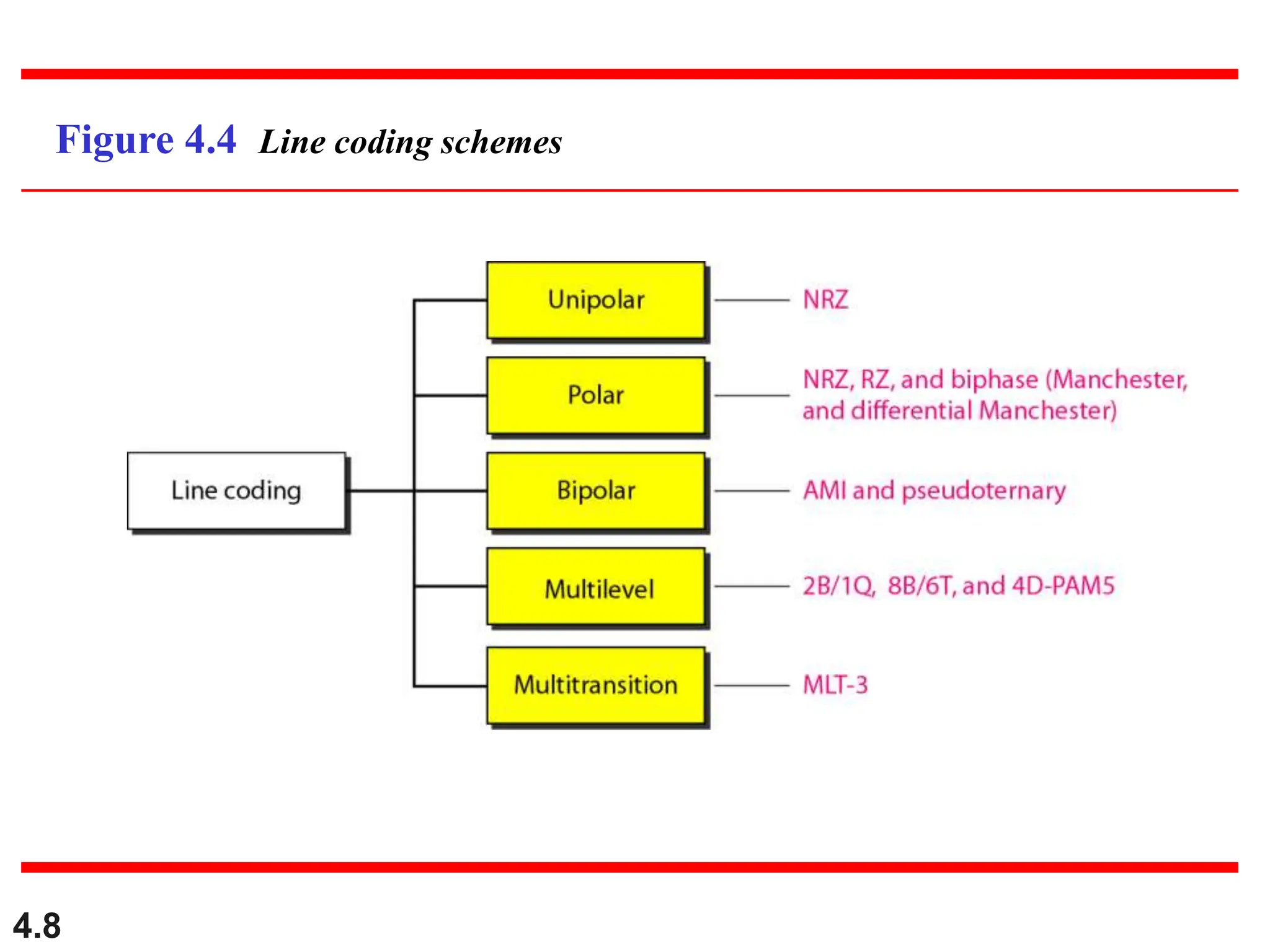
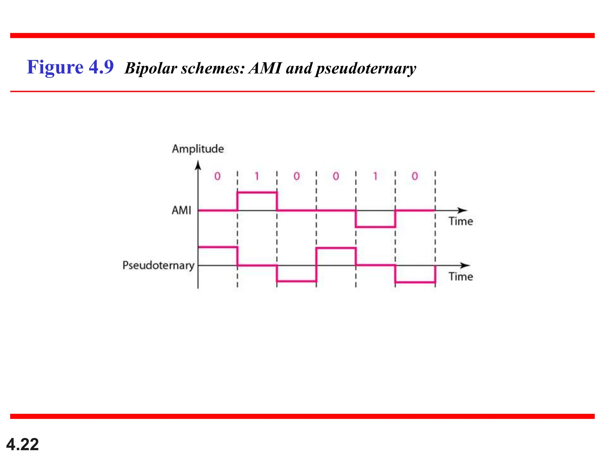
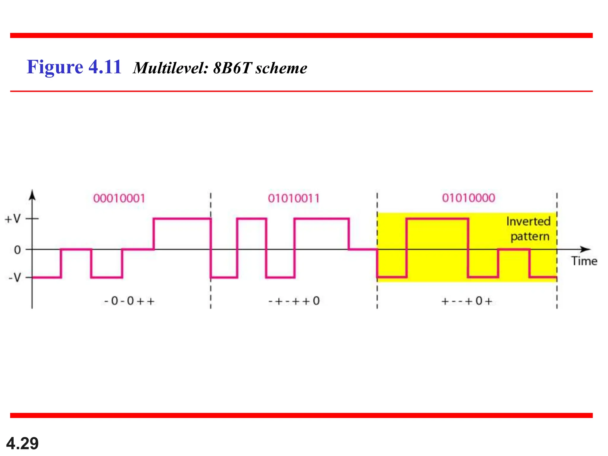
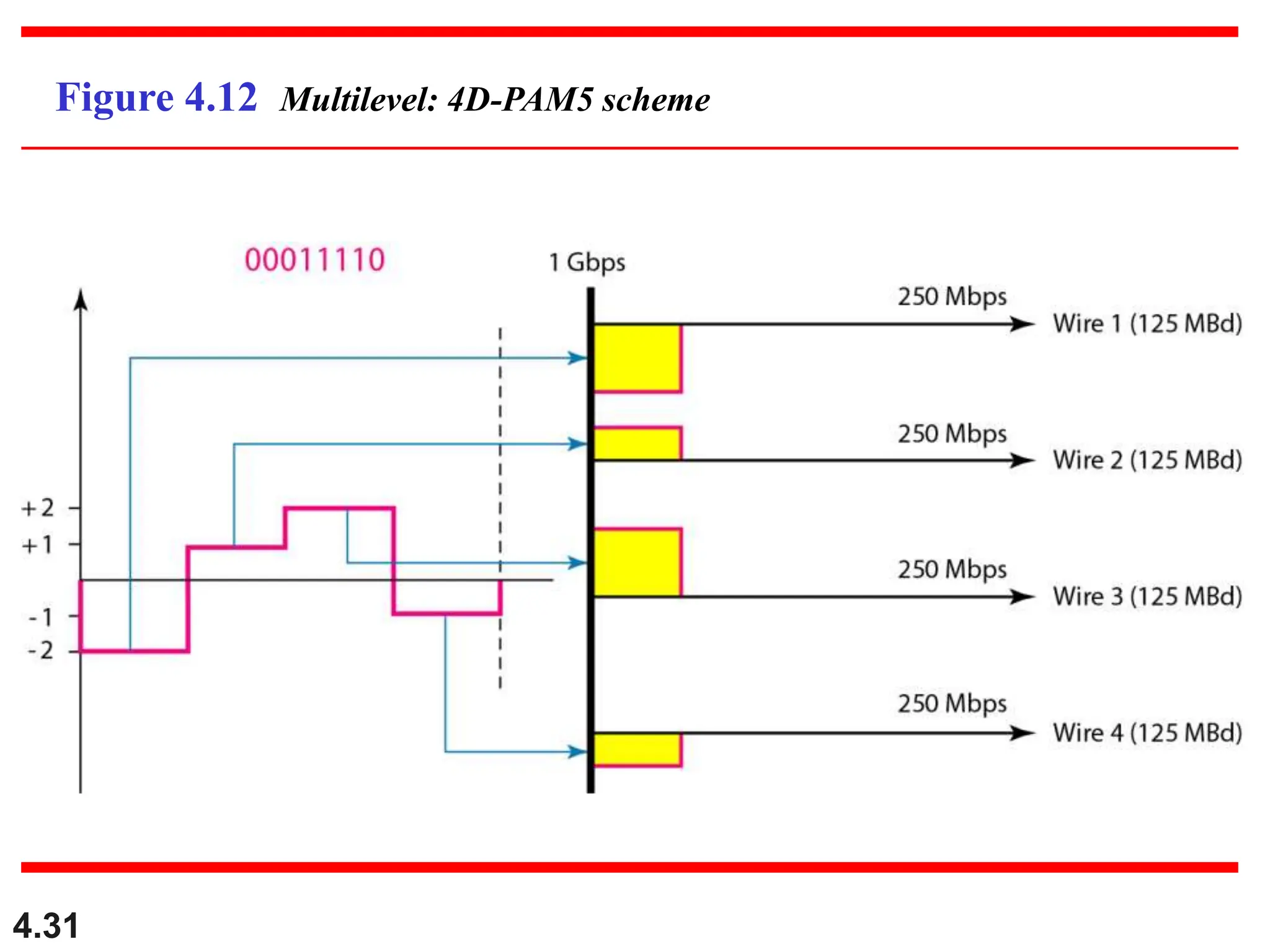
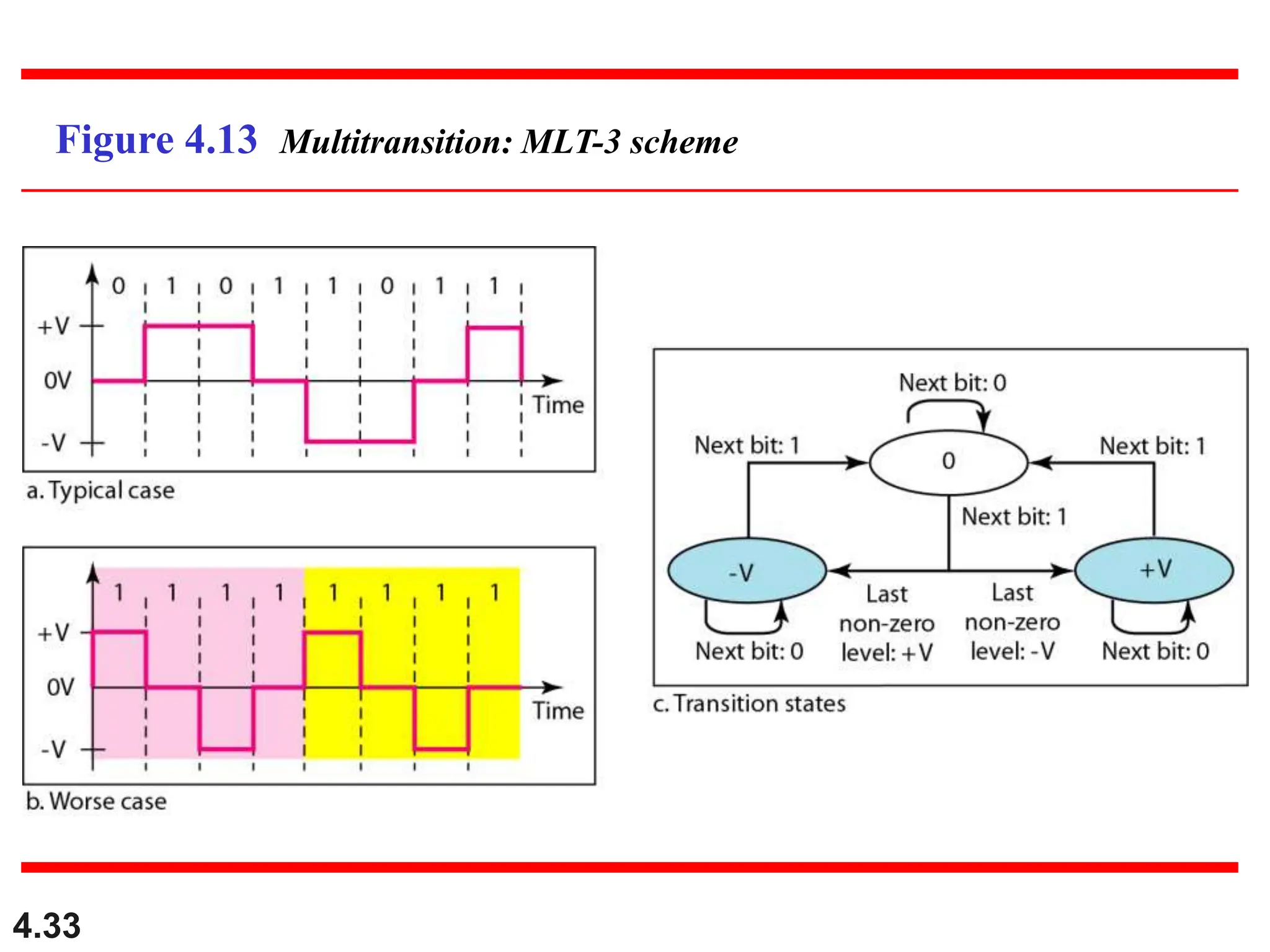
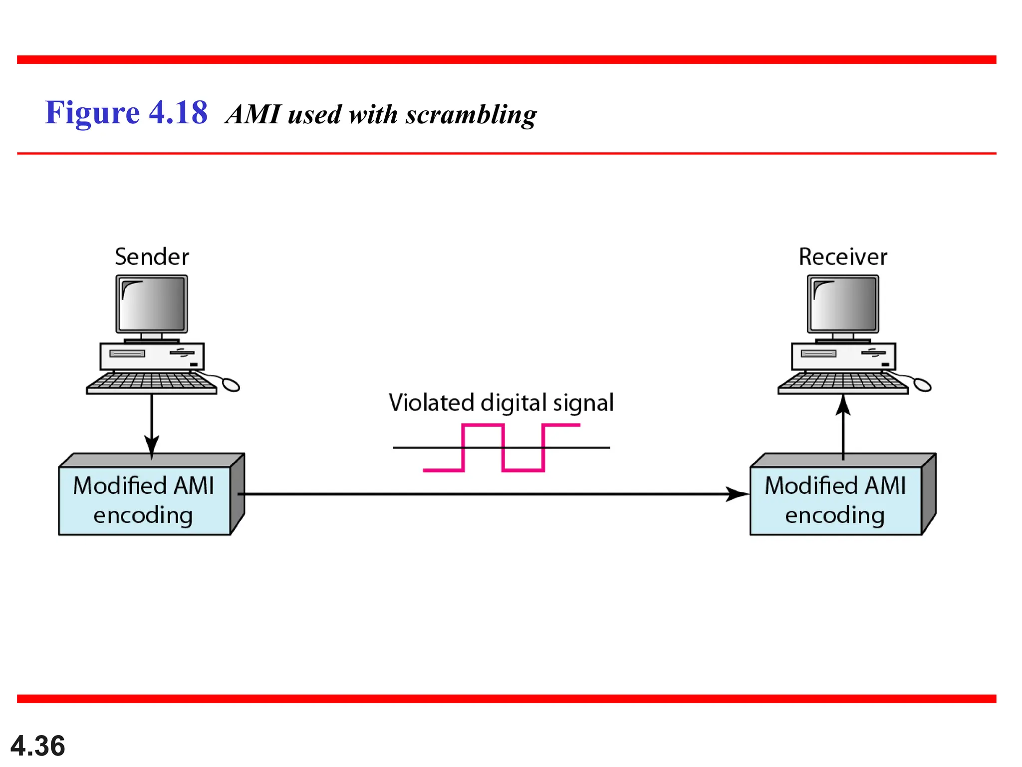
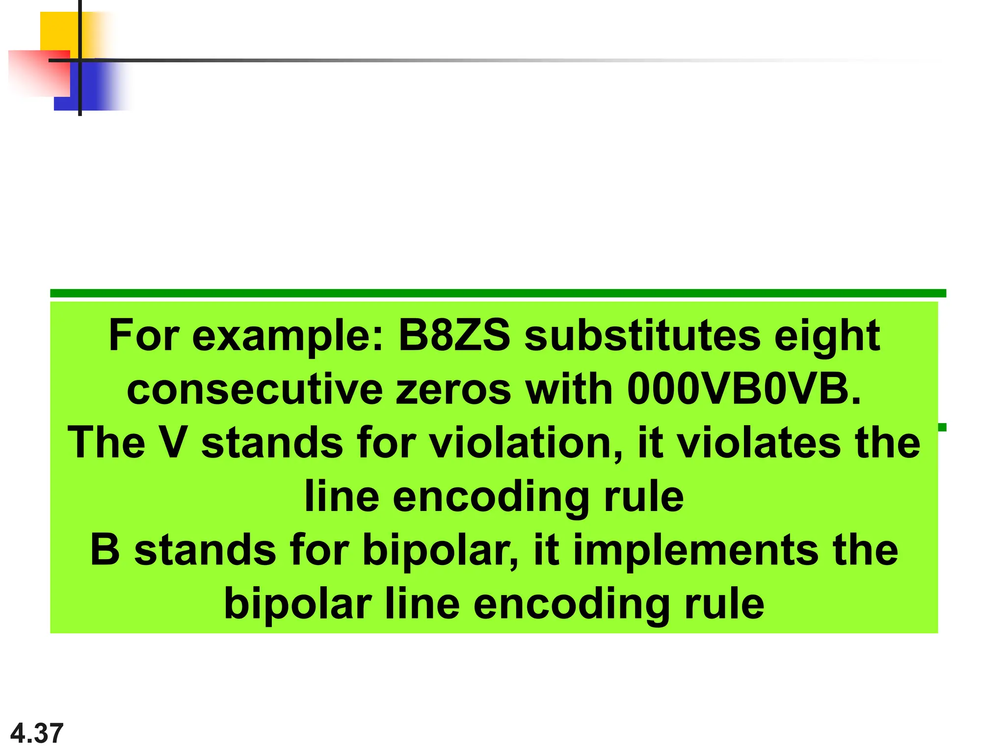
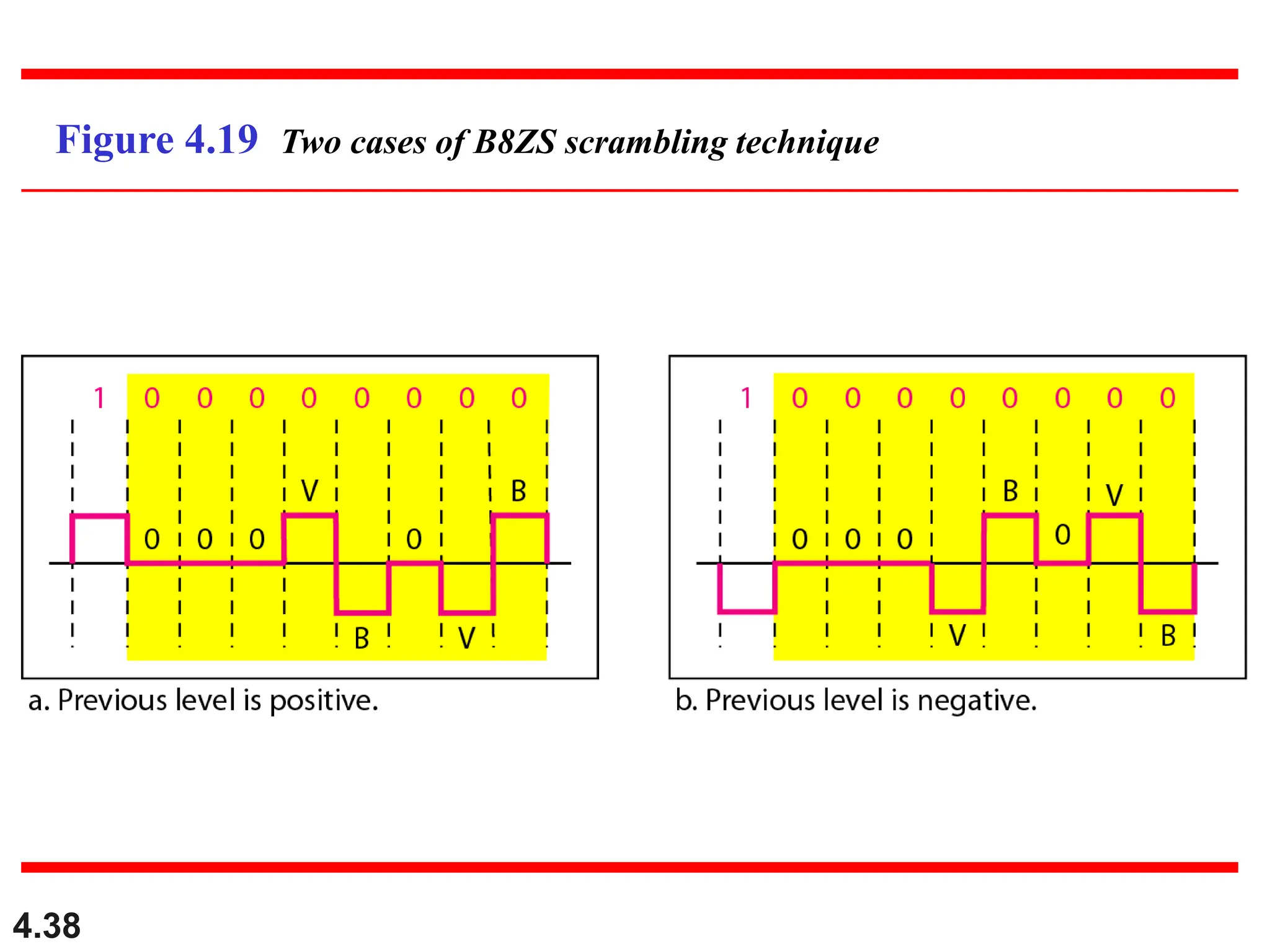
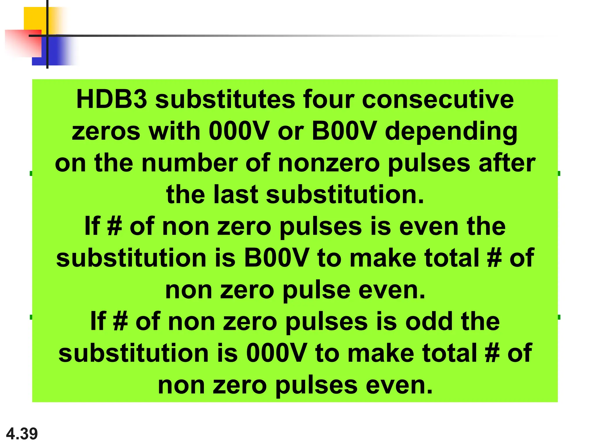
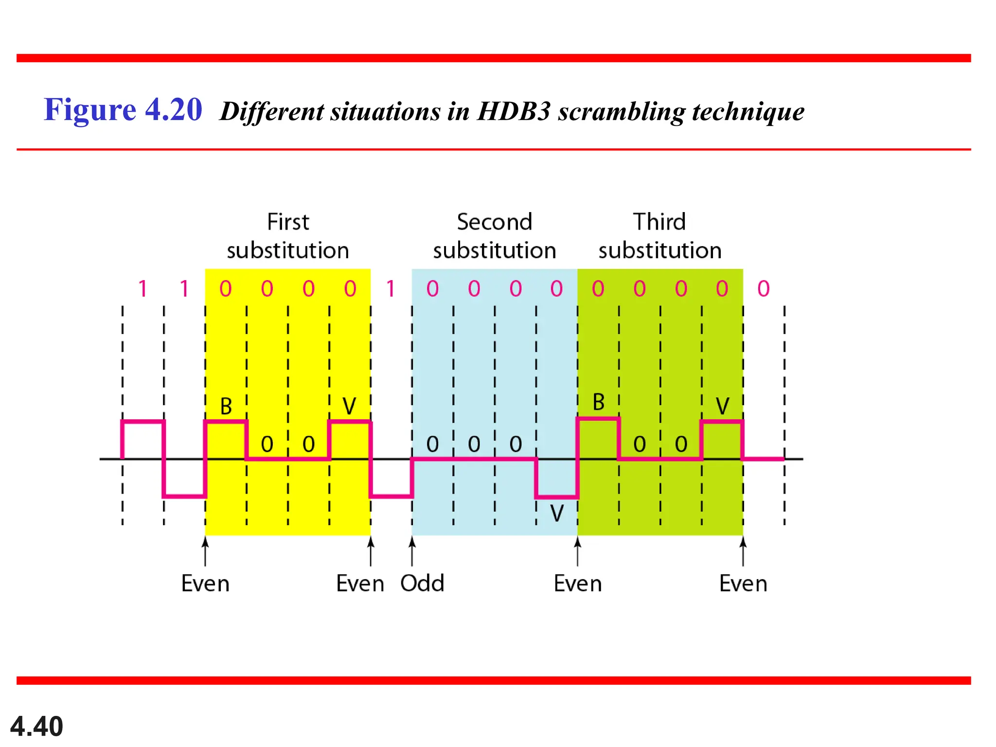
2. 4.2
Although the actual bandwidth of a
digital signal is infinite, the effective
bandwidth is finite.
Note
3. 4.3
Considerations for choosing a good
signal element referred to as line
encoding
Baseline wandering - a receiver will evaluate
the average power of the received signal
(called the baseline) and use that to determine
the value of the incoming data elements. If
the incoming signal does not vary over a long
period of time, the baseline will drift and thus
cause errors in detection of incoming data
elements.
A good line encoding scheme will prevent long
runs of fixed amplitude.
4. 4.4
Line encoding C/Cs
DC components - when the voltage
level remains constant for long periods
of time, there is an increase in the low
frequencies of the signal. Most channels
are bandpass and may not support the
low frequencies.
This will require the removal of the dc
component of a transmitted signal.
5. 4.5
Line encoding C/Cs
Self synchronization - the clocks at the
sender and the receiver must have the
same bit interval.
If the receiver clock is faster or slower it
will misinterpret the incoming bit
stream.
7. 4.7
In a digital transmission, the receiver clock is 0.1 percent
faster than the sender clock. How many extra bits per
second does the receiver receive if the data rate is
1 kbps? How many if the data rate is 1 Mbps?
Solution
At 1 kbps, the receiver receives 1001 bps instead of 1000
bps.
Example 4.3
At 1 Mbps, the receiver receives 1,001,000 bps instead of
1,000,000 bps.
9. 4.9
Unipolar
All signal levels are on one side of the time
axis - either above or below
NRZ - Non Return to Zero scheme is an
example of this code. The signal level does
not return to zero during a symbol
transmission.
Scheme is prone to baseline wandering and
DC components. It has no synchronization or
any error detection. It is simple but costly in
power consumption.
11. 4.11
Polar - NRZ
The voltages are on both sides of the time
axis.
Polar NRZ scheme can be implemented with
two voltages. E.g. +V for 1 and -V for 0.
There are two versions:
NZR - Level (NRZ-L) - positive voltage for one
symbol and negative for the other
NRZ - Inversion (NRZ-I) - the change or lack of
change in polarity determines the value of a
symbol. E.g. a “1” symbol inverts the polarity a “0”
does not.
13. 4.13
In NRZ-L the level of the voltage
determines the value of the bit.
In NRZ-I the inversion
or the lack of inversion
determines the value of the bit.
Note
14. 4.14
NRZ-L and NRZ-I both have a DC
component problem and baseline
wandering, it is worse for NRZ-L. Both
have no self synchronization &no error
detection. Both are relatively simple to
implement.
Note
15. 4.15
Polar - RZ
The Return to Zero (RZ) scheme uses three
voltage values. +, 0, -.
Each symbol has a transition in the middle.
Either from high to zero or from low to zero.
This scheme has more signal transitions (two
per symbol) and therefore requires a wider
bandwidth.
No DC components or baseline wandering.
Self synchronization - transition indicates
symbol value.
More complex as it uses three voltage level.
It has no error detection capability.
17. 4.17
Polar - Biphase: Manchester and
Differential Manchester
Manchester coding consists of combining the
NRZ-L and RZ schemes.
Every symbol has a level transition in the middle:
from high to low or low to high. Uses only two
voltage levels.
Differential Manchester coding consists of
combining the NRZ-I and RZ schemes.
Every symbol has a level transition in the middle.
But the level at the beginning of the symbol is
determined by the symbol value. One symbol
causes a level change the other does not.
19. 4.19
In Manchester and differential
Manchester encoding, the transition
at the middle of the bit is used for
synchronization.
Note
20. 4.20
The minimum bandwidth of Manchester
and differential Manchester is 2 times
that of NRZ. The is no DC component
and no baseline wandering. None of
these codes has error detection.
Note
21. 4.21
Bipolar - AMI and Pseudoternary
Code uses 3 voltage levels: - +, 0, -, to
represent the symbols (note not transitions to
zero as in RZ).
Voltage level for one symbol is at “0” and the
other alternates between + & -.
Bipolar Alternate Mark Inversion (AMI) - the
“0” symbol is represented by zero voltage
and the “1” symbol alternates between +V
and -V.
Pseudoternary is the reverse of AMI.
23. 4.23
It is a better alternative to NRZ.
Has no DC component or baseline
wandering.
Has no self synchronization because
long runs of “0”s results in no signal
transitions.
No error detection.
24. 4.24
Multilevel Schemes
In these schemes we increase the number of
data bits per symbol thereby increasing the
bit rate.
Since we are dealing with binary data we only
have 2 types of data element a 1 or a 0.
We can combine the 2 data elements into a
pattern of “m” elements to create “2m”
symbols.
If we have L signal levels, we can use “n”
signal elements to create Ln signal elements.
25. 4.25
In mBnL schemes, a pattern of m data
elements is encoded as a pattern of n
signal elements in which 2m ≤ Ln.
Note
26. 4.26
Representing Multilevel Codes
We use the notation mBnL, where m is
the length of the binary pattern, B
represents binary data, n represents the
length of the signal pattern and L the
number of levels.
L = B binary, L = T for 3 ternary, L = Q
for 4 quaternary.
28. 4.28
Redundancy
In the 2B1Q scheme we have no redundancy
and we see that a DC component is present.
If we use a code with redundancy we can
decide to use only “0” or “+” weighted codes
(more +’s than -’s in the signal element) and
invert any code that would create a DC
component. E.g. ‘+00++-’ -> ‘-00--+’
Receiver will know when it receives a “-”
weighted code that it should invert it as it
doesn’t represent any valid symbol.
30. 4.30
Multilevel using multiple channels
In some cases, we split the signal transmission
up and distribute it over several links.
The separate segments are transmitted
simultaneously. This reduces the signalling
rate per link -> lower bandwidth.
This requires all bits for a code to be stored.
xD: means that we use ‘x’ links
YYYz: We use ‘z’ levels of modulation where
YYY represents the type of modulation (e.g.
pulse ampl. mod. PAM).
Codes are represented as: xD-YYYz
32. 4.32
Multitransition Coding
Because of synchronization requirements we force
transitions. This can result in very high bandwidth
requirements -> more transitions than are bits (e.g.
mid bit transition with inversion).
Codes can be created that are differential at the bit
level forcing transitions at bit boundaries. This results
in a bandwidth requirement that is equivalent to the
bit rate.
In some instances, the bandwidth requirement may
even be lower, due to repetitive patterns resulting in
a periodic signal.
34. 4.34
MLT-3
Signal rate is same as NRZ-I
But because of the resulting bit pattern,
we have a periodic signal for worst case
bit pattern: 1111
This can be approximated as an analog
signal a frequency 1/4 the bit rate!
35. 4.35
Scrambling
The best code is one that does not increase
the bandwidth for synchronization and has no
DC components.
Scrambling is a technique used to create a
sequence of bits that has the required c/c’s for
transmission - self clocking, no low
frequencies, no wide bandwidth.
It is implemented at the same time as
encoding, the bit stream is created on the fly.
It replaces ‘unfriendly’ runs of bits with a
violation code that is easy to recognize and
removes the unfriendly c/c.
37. 4.37
For example: B8ZS substitutes eight
consecutive zeros with 000VB0VB.
The V stands for violation, it violates the
line encoding rule
B stands for bipolar, it implements the
bipolar line encoding rule
39. 4.39
HDB3 substitutes four consecutive
zeros with 000V or B00V depending
on the number of nonzero pulses after
the last substitution.
If # of non zero pulses is even the
substitution is B00V to make total # of
non zero pulse even.
If # of non zero pulses is odd the
substitution is 000V to make total # of
non zero pulses even.