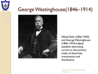
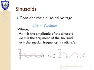
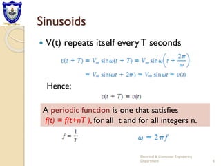
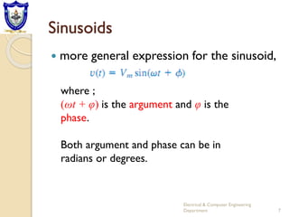
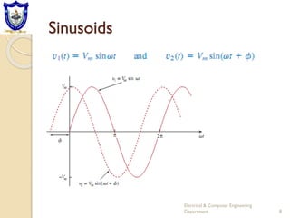
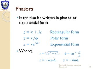
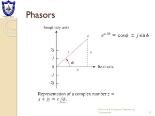
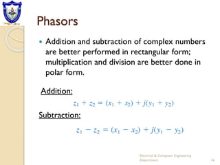
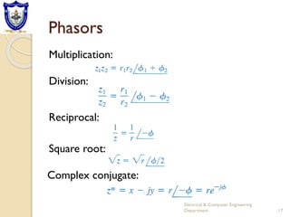
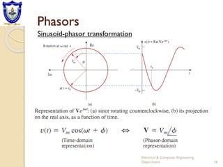
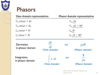
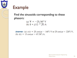
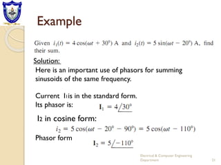
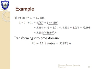
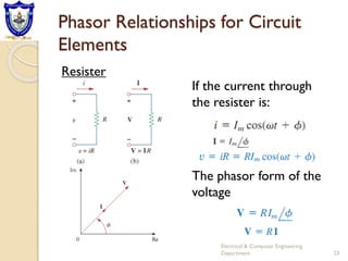
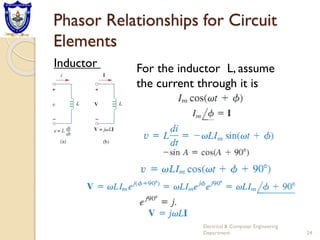
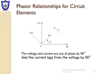
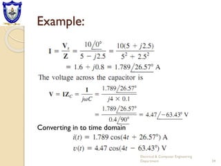
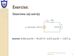
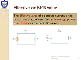
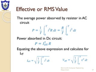
Lecture 2
AC Circuit Analysis
George Westinghouse(1846–1914)
2
Electrical & Computer Engineering
Department
NikolaTesla (1856–1943)
and GeorgeWestinghouse
(1846–1914) helped
establish alternating
current as the primary
mode of electricity
transmission and
distribution.
Introduction:
 Thus far our analysis has been limited for
the most part to dc circuits; those circuits
excited by constant or time-invariant
sources.
 We now begin the analysis of circuits in
which the source voltage or current is time-
varying.
 In this chapter, we are particularly interested
in sinusoidally time-varying excitation, or
simply, excitation by a sinusoid.
3
Electrical & Computer Engineering
Department
Introduction:
 A sinusoid is a signal that has the form of
the sine or cosine function.
 A sinusoidal current is usually referred to as
alternating current (ac).
 Such a current reverses at regular time
intervals and has alternately positive and
negative values.
 Circuits driven by sinusoidal current, or
voltage sources are called ac circuits
4
Electrical & Computer Engineering
Department
Sinusoids
 Consider the sinusoidal voltage
Where;
Vm = is the amplitude of the sinusoid
ωt = is the argument of the sinusoid
ω = the angular frequency in radians/s
5
Electrical & Computer Engineering
Department
Sinusoids
 V(t) repeats itself everyT seconds
Hence;
A periodic function is one that satisfies
f(t) = f(t+nT ), for all t and for all integers n.
6
Electrical & Computer Engineering
Department
Sinusoids
 more general expression for the sinusoid,
where ;
(ωt + φ) is the argument and φ is the
phase.
Both argument and phase can be in
radians or degrees.
7
Electrical & Computer Engineering
Department
Sinusoids
8
Electrical & Computer Engineering
Department
Sinusoids
 The starting point of v2 in Figure occurs first in
time. Therefore, we say that v2 leads v1 by φ or
that v1 lags v2 by φ
 we also say that v1and v2 are out of phase.
 If φ = 0 then V1 and v2 are said to be in phase.
A sinusoid can be expressed in either sine or
cosine form
9
Electrical & Computer Engineering
Department
Sinusoids
10
Electrical & Computer Engineering
Department
Trigonometric properties
Example 1
Find the amplitude, phase, period, and
frequency of a sinusoid:
Solution:
11
Electrical & Computer Engineering
Department
Example 2
Calculate the phase angle between
and v2=
In order to compare v1 and v2 we must
express them in the same form. If we express
them in cosine form with positive amplitudes
Solution:
V2 leadsV1 by 30 degree
12
Electrical & Computer Engineering
Department
Phasors
A phasor is a complex number that represents
the amplitude and phase of a sinusoid.
Electrical & Computer Engineering
Department 13
A complex number z can be written in
rectangular form as
Phasors provide a simple means of analyzing
linear circuits excited by sinusoidal sources;
Phasors
 It can also be written in phasor or
exponential form
 Where;
Electrical & Computer Engineering
Department 14
Phasors
Electrical & Computer Engineering
Department 15
Phasors
 Addition and subtraction of complex numbers
are better performed in rectangular form;
multiplication and division are better done in
polar form.
Electrical & Computer Engineering
Department 16
Addition:
Subtraction:
Phasors
Electrical & Computer Engineering
Department 17
Multiplication:
Division:
Reciprocal:
Square root:
Complex conjugate:
Phasors
Electrical & Computer Engineering
Department 18
Sinusoid-phasor transformation
Phasors
Electrical & Computer Engineering
Department 19
Derivation
in phasor domain
Integration
in phasor domain
Example
Find the sinusoids corresponding to these
phasors:
Electrical & Computer Engineering
Department 20
12j -j^2 5 but j^2= -1
i=5+12j
Example
Electrical & Computer Engineering
Department 21
Here is an important use of phasors for summing
sinusoids of the same frequency.
I2 in cosine form:
Phasor form
Solution:
Current I1is in the standard form.
Its phasor is:
Example
Electrical & Computer Engineering
Department 22
Transforming into time domain:
Phasor Relationships for Circuit
Elements
Electrical & Computer Engineering
Department 23
Resister
If the current through
the resister is:
The phasor form of the
voltage
Phasor Relationships for Circuit
Elements
Electrical & Computer Engineering
Department 24
Inductor For the inductor L, assume
the current through it is
Phasor Relationships for Circuit
Elements
Electrical & Computer Engineering
Department 25
The voltage and current are out of phase by 90˚
And the current lags from the voltage by 90˚
Phasor Relationships for Circuit
Elements
Electrical & Computer Engineering
Department 26
Capacitor :
For the capacitor C, assume the voltage across it
is
The voltage and current are out of phase by 90˚
And the current leads the voltage by 90˚
Phasor Relationships for Circuit
Elements
Electrical & Computer Engineering
Department 27
Summary for voltage current relationship
Example:
Electrical & Computer Engineering
Department 28
The voltage v=12cos(60t + 45˚) is applied to a
0.1-H inductor. Find the steady-state current
through the inductor
Exercise
Electrical & Computer Engineering
Department 29
If voltage v=10cos(100t+30˚) is applied to a 50μF
capacitor, calculate the current through the
capacitor.
Impedance and Admittance
Electrical & Computer Engineering
Department 30
The impedance Z of a circuit is the ratio of the
phasor voltage V to the phasor current I,
measured in ohms (Ω).
As a complex quantity
Impedance and Admittance
Electrical & Computer Engineering
Department 31
where R= Re Z is the resistance and X= Im Z is
the reactance
The AdmittanceY is the reciprocal of
impedance, measured in Siemens(S)
Impedance and Admittance
Electrical & Computer Engineering
Department 32
Example:
Electrical & Computer Engineering
Department 33
Find i(t) and v(t) in the circuit shown in Fig
Solution:
Example:
Electrical & Computer Engineering
Department 34
Converting in to time domain
Exercise:
Electrical & Computer Engineering
Department 35
Determine v(t) and i(t)
Effective or RMSValue
Electrical & Computer Engineering
Department 36
The Effective value of a periodic current is the
dc current that delivers the same average power
to a resistor as the periodic current.
Effective or RMSValue
The average power absorved by resister in AC
circuit
Power absorbed in Dc circuit:
Equating the above expression and calculate for
Ieff
Electrical & Computer Engineering
Department 37
Effective or RMSValue
 The effective value is the (square) root of
the mean(or average) of the square of
the periodic signal.
 Thus, the effective value is often known as
the root-mean-square value, or rms
value for short.
Electrical & Computer Engineering
Department 38
Effective or RMSValue
 For periodic function X(t) in general;
Electrical & Computer Engineering
Department 39
The effective value of a periodic signal is its
root mean square (rms) value.
For the sinusoid , the
effective or rms value is
Effective or RMSValue
Electrical & Computer Engineering
Department 40
Effective or RMSValue
 Average power in terms of RMS value
 Average power absorbed by resister R
Electrical & Computer Engineering
Department 41
Effective or RMSValue
 When a sinusoidal voltage or current is
specified, it is often in terms of its maximum
(or peak) value or its rms value, since its
average value is zero.
 The power industries specify phasor
magnitudes in terms of their RMS values
rather than peak values
 For instance, the 220V available at every
household is the rms value of the voltage
from the power company.
Electrical & Computer Engineering
Department 42
AC power Analysis
 Power analysis is of paramount importance.
 Power is the most important quantity in electric
utilities, electronic, and communication systems,
because such systems involve transmission of
power from one point to another.
 Every industrial and household electrical device
i.e. every fan, motor, lamp, pressing iron,TV,
personal computer has a power rating that
indicates how much power the equipment
requires.
Electrical & Computer Engineering
Department 43
AC power Analysis
 exceeding the power rating can do
permanent damage to an appliance.
 The most common form of electric
power is 50- or 60-Hz ac power.
Electrical & Computer Engineering
Department 44
Instantaneous and Average Power
The instantaneous power (in watts) is the
power at any instant of time.
Electrical & Computer Engineering
Department 45
It is the rate at which an element absorbs
energy.
Let the voltage and current at the terminals of
the circuit be:
Instantaneous and Average Power
The instantaneous power:
Electrical & Computer Engineering
Department 46
Applying trigonometry:
Instantaneous and Average Power
 The instantaneous power has two parts.
 The first part is constant or time
independent. Its value depends on the
phase difference between the voltage and
the current.
 The second part is a sinusoidal function
whose frequency is twice the angular
frequency of the voltage or current.
Electrical & Computer Engineering
Department 47
Instantaneous and Average Power
Electrical & Computer Engineering
Department 48
Figure: The instantaneous power entering a circuit.
Instantaneous and Average Power
 The instantaneous power changes with
time and is therefore difficult to measure.
The average power is more convenient to
measure.
Electrical & Computer Engineering
Department 49
The Average power, in watts, is the average of
the instantaneous power over one period.
Thus, the average power is given by
Instantaneous and Average Power
Substituting
Electrical & Computer Engineering
Department 50
Instantaneous and Average Power
 The first integrand is constant, and the average
of a constant is the same constant.
 The second integrand is a sinusoid.We know
that the average of a sinusoid over its period is
zero.
 Hence, the average power;
 NB:
Electrical & Computer Engineering
Department 51
Instantaneous and Average Power
The phasor forms of v(t) and i(t)
Electrical & Computer Engineering
Department 52
The real part is the average power P
Instantaneous power in phasor form
Instantaneous and Average Power
Electrical & Computer Engineering
Department 53
Two special cases
i. The voltage & current are in phase i.e. vi
Which implies resistive load (i.e. R)
ii. When
Purely reactive circuit (i.e. L or C)
 End
Electrical & Computer Engineering
Department 54

Ch-2 AC.pdf

  • 1.
  • 2.
    George Westinghouse(1846–1914) 2 Electrical &Computer Engineering Department NikolaTesla (1856–1943) and GeorgeWestinghouse (1846–1914) helped establish alternating current as the primary mode of electricity transmission and distribution.
  • 3.
    Introduction:  Thus farour analysis has been limited for the most part to dc circuits; those circuits excited by constant or time-invariant sources.  We now begin the analysis of circuits in which the source voltage or current is time- varying.  In this chapter, we are particularly interested in sinusoidally time-varying excitation, or simply, excitation by a sinusoid. 3 Electrical & Computer Engineering Department
  • 4.
    Introduction:  A sinusoidis a signal that has the form of the sine or cosine function.  A sinusoidal current is usually referred to as alternating current (ac).  Such a current reverses at regular time intervals and has alternately positive and negative values.  Circuits driven by sinusoidal current, or voltage sources are called ac circuits 4 Electrical & Computer Engineering Department
  • 5.
    Sinusoids  Consider thesinusoidal voltage Where; Vm = is the amplitude of the sinusoid ωt = is the argument of the sinusoid ω = the angular frequency in radians/s 5 Electrical & Computer Engineering Department
  • 6.
    Sinusoids  V(t) repeatsitself everyT seconds Hence; A periodic function is one that satisfies f(t) = f(t+nT ), for all t and for all integers n. 6 Electrical & Computer Engineering Department
  • 7.
    Sinusoids  more generalexpression for the sinusoid, where ; (ωt + φ) is the argument and φ is the phase. Both argument and phase can be in radians or degrees. 7 Electrical & Computer Engineering Department
  • 8.
    Sinusoids 8 Electrical & ComputerEngineering Department
  • 9.
    Sinusoids  The startingpoint of v2 in Figure occurs first in time. Therefore, we say that v2 leads v1 by φ or that v1 lags v2 by φ  we also say that v1and v2 are out of phase.  If φ = 0 then V1 and v2 are said to be in phase. A sinusoid can be expressed in either sine or cosine form 9 Electrical & Computer Engineering Department
  • 10.
    Sinusoids 10 Electrical & ComputerEngineering Department Trigonometric properties
  • 11.
    Example 1 Find theamplitude, phase, period, and frequency of a sinusoid: Solution: 11 Electrical & Computer Engineering Department
  • 12.
    Example 2 Calculate thephase angle between and v2= In order to compare v1 and v2 we must express them in the same form. If we express them in cosine form with positive amplitudes Solution: V2 leadsV1 by 30 degree 12 Electrical & Computer Engineering Department
  • 13.
    Phasors A phasor isa complex number that represents the amplitude and phase of a sinusoid. Electrical & Computer Engineering Department 13 A complex number z can be written in rectangular form as Phasors provide a simple means of analyzing linear circuits excited by sinusoidal sources;
  • 14.
    Phasors  It canalso be written in phasor or exponential form  Where; Electrical & Computer Engineering Department 14
  • 15.
    Phasors Electrical & ComputerEngineering Department 15
  • 16.
    Phasors  Addition andsubtraction of complex numbers are better performed in rectangular form; multiplication and division are better done in polar form. Electrical & Computer Engineering Department 16 Addition: Subtraction:
  • 17.
    Phasors Electrical & ComputerEngineering Department 17 Multiplication: Division: Reciprocal: Square root: Complex conjugate:
  • 18.
    Phasors Electrical & ComputerEngineering Department 18 Sinusoid-phasor transformation
  • 19.
    Phasors Electrical & ComputerEngineering Department 19 Derivation in phasor domain Integration in phasor domain
  • 20.
    Example Find the sinusoidscorresponding to these phasors: Electrical & Computer Engineering Department 20 12j -j^2 5 but j^2= -1 i=5+12j
  • 21.
    Example Electrical & ComputerEngineering Department 21 Here is an important use of phasors for summing sinusoids of the same frequency. I2 in cosine form: Phasor form Solution: Current I1is in the standard form. Its phasor is:
  • 22.
    Example Electrical & ComputerEngineering Department 22 Transforming into time domain:
  • 23.
    Phasor Relationships forCircuit Elements Electrical & Computer Engineering Department 23 Resister If the current through the resister is: The phasor form of the voltage
  • 24.
    Phasor Relationships forCircuit Elements Electrical & Computer Engineering Department 24 Inductor For the inductor L, assume the current through it is
  • 25.
    Phasor Relationships forCircuit Elements Electrical & Computer Engineering Department 25 The voltage and current are out of phase by 90˚ And the current lags from the voltage by 90˚
  • 26.
    Phasor Relationships forCircuit Elements Electrical & Computer Engineering Department 26 Capacitor : For the capacitor C, assume the voltage across it is The voltage and current are out of phase by 90˚ And the current leads the voltage by 90˚
  • 27.
    Phasor Relationships forCircuit Elements Electrical & Computer Engineering Department 27 Summary for voltage current relationship
  • 28.
    Example: Electrical & ComputerEngineering Department 28 The voltage v=12cos(60t + 45˚) is applied to a 0.1-H inductor. Find the steady-state current through the inductor
  • 29.
    Exercise Electrical & ComputerEngineering Department 29 If voltage v=10cos(100t+30˚) is applied to a 50μF capacitor, calculate the current through the capacitor.
  • 30.
    Impedance and Admittance Electrical& Computer Engineering Department 30 The impedance Z of a circuit is the ratio of the phasor voltage V to the phasor current I, measured in ohms (Ω). As a complex quantity
  • 31.
    Impedance and Admittance Electrical& Computer Engineering Department 31 where R= Re Z is the resistance and X= Im Z is the reactance The AdmittanceY is the reciprocal of impedance, measured in Siemens(S)
  • 32.
    Impedance and Admittance Electrical& Computer Engineering Department 32
  • 33.
    Example: Electrical & ComputerEngineering Department 33 Find i(t) and v(t) in the circuit shown in Fig Solution:
  • 34.
    Example: Electrical & ComputerEngineering Department 34 Converting in to time domain
  • 35.
    Exercise: Electrical & ComputerEngineering Department 35 Determine v(t) and i(t)
  • 36.
    Effective or RMSValue Electrical& Computer Engineering Department 36 The Effective value of a periodic current is the dc current that delivers the same average power to a resistor as the periodic current.
  • 37.
    Effective or RMSValue Theaverage power absorved by resister in AC circuit Power absorbed in Dc circuit: Equating the above expression and calculate for Ieff Electrical & Computer Engineering Department 37
  • 38.
    Effective or RMSValue The effective value is the (square) root of the mean(or average) of the square of the periodic signal.  Thus, the effective value is often known as the root-mean-square value, or rms value for short. Electrical & Computer Engineering Department 38
  • 39.
    Effective or RMSValue For periodic function X(t) in general; Electrical & Computer Engineering Department 39 The effective value of a periodic signal is its root mean square (rms) value. For the sinusoid , the effective or rms value is
  • 40.
    Effective or RMSValue Electrical& Computer Engineering Department 40
  • 41.
    Effective or RMSValue Average power in terms of RMS value  Average power absorbed by resister R Electrical & Computer Engineering Department 41
  • 42.
    Effective or RMSValue When a sinusoidal voltage or current is specified, it is often in terms of its maximum (or peak) value or its rms value, since its average value is zero.  The power industries specify phasor magnitudes in terms of their RMS values rather than peak values  For instance, the 220V available at every household is the rms value of the voltage from the power company. Electrical & Computer Engineering Department 42
  • 43.
    AC power Analysis Power analysis is of paramount importance.  Power is the most important quantity in electric utilities, electronic, and communication systems, because such systems involve transmission of power from one point to another.  Every industrial and household electrical device i.e. every fan, motor, lamp, pressing iron,TV, personal computer has a power rating that indicates how much power the equipment requires. Electrical & Computer Engineering Department 43
  • 44.
    AC power Analysis exceeding the power rating can do permanent damage to an appliance.  The most common form of electric power is 50- or 60-Hz ac power. Electrical & Computer Engineering Department 44
  • 45.
    Instantaneous and AveragePower The instantaneous power (in watts) is the power at any instant of time. Electrical & Computer Engineering Department 45 It is the rate at which an element absorbs energy. Let the voltage and current at the terminals of the circuit be:
  • 46.
    Instantaneous and AveragePower The instantaneous power: Electrical & Computer Engineering Department 46 Applying trigonometry:
  • 47.
    Instantaneous and AveragePower  The instantaneous power has two parts.  The first part is constant or time independent. Its value depends on the phase difference between the voltage and the current.  The second part is a sinusoidal function whose frequency is twice the angular frequency of the voltage or current. Electrical & Computer Engineering Department 47
  • 48.
    Instantaneous and AveragePower Electrical & Computer Engineering Department 48 Figure: The instantaneous power entering a circuit.
  • 49.
    Instantaneous and AveragePower  The instantaneous power changes with time and is therefore difficult to measure. The average power is more convenient to measure. Electrical & Computer Engineering Department 49 The Average power, in watts, is the average of the instantaneous power over one period. Thus, the average power is given by
  • 50.
    Instantaneous and AveragePower Substituting Electrical & Computer Engineering Department 50
  • 51.
    Instantaneous and AveragePower  The first integrand is constant, and the average of a constant is the same constant.  The second integrand is a sinusoid.We know that the average of a sinusoid over its period is zero.  Hence, the average power;  NB: Electrical & Computer Engineering Department 51
  • 52.
    Instantaneous and AveragePower The phasor forms of v(t) and i(t) Electrical & Computer Engineering Department 52 The real part is the average power P Instantaneous power in phasor form
  • 53.
    Instantaneous and AveragePower Electrical & Computer Engineering Department 53 Two special cases i. The voltage & current are in phase i.e. vi Which implies resistive load (i.e. R) ii. When Purely reactive circuit (i.e. L or C)
  • 54.
     End Electrical &Computer Engineering Department 54