- CT scanning was invented in 1972 by Godfrey Hounsfield and Allan Cormack, who shared the 1979 Nobel Prize in Physiology or Medicine for their work.
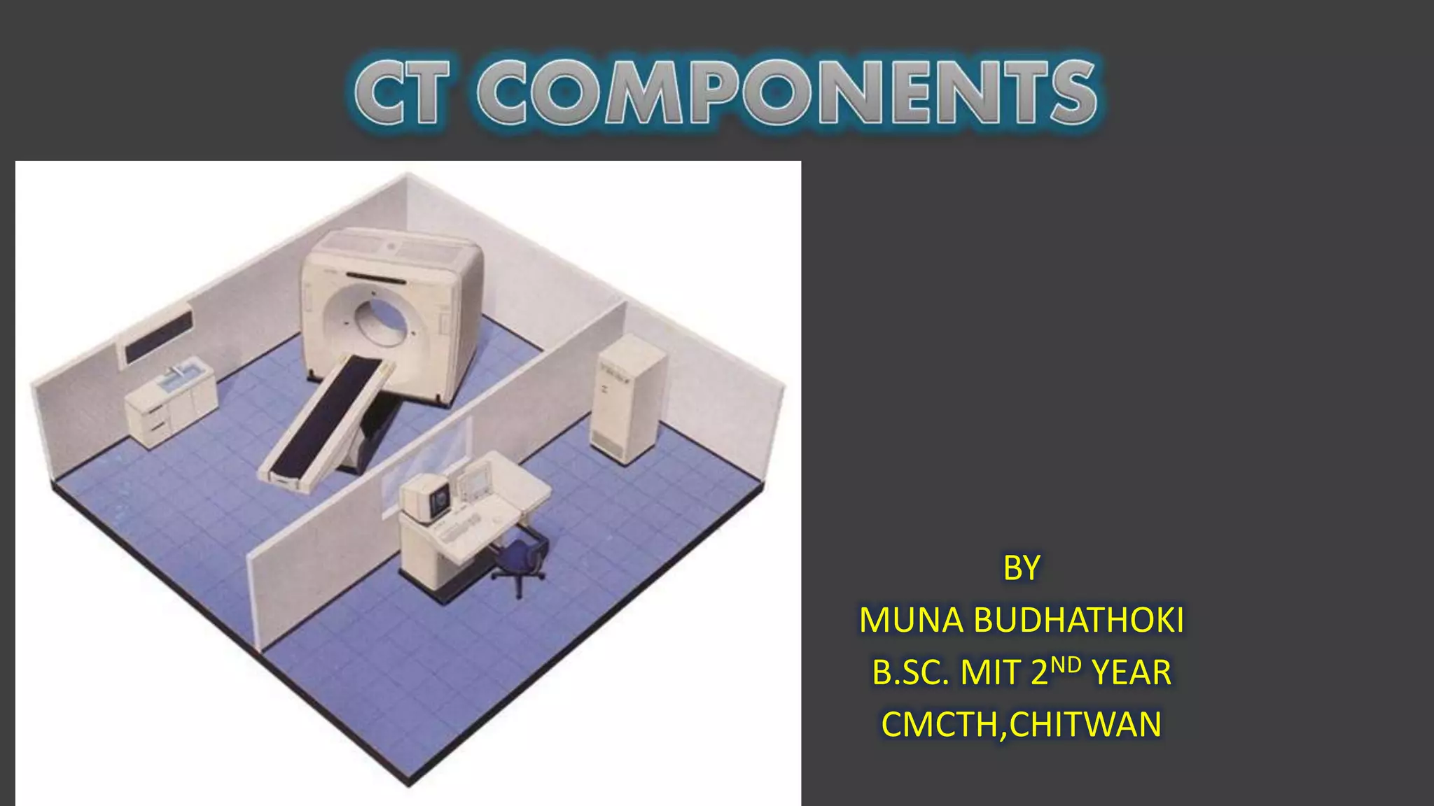
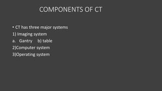
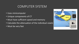
- A CT scanner consists of three major systems: the imaging system, which includes the gantry and patient table; the computer system; and the operating system.
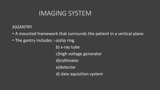
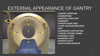
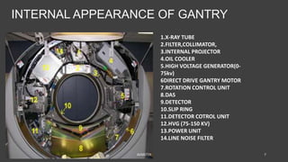
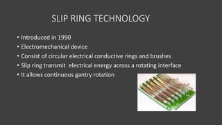
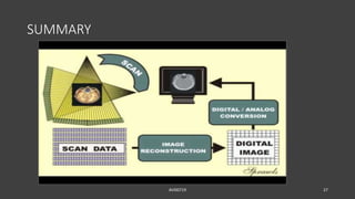
- The gantry houses the x-ray tube, detectors, and other components which rotate around the patient to acquire cross-sectional images, while slip ring technology allows for continuous rotation. X-ray data is processed by the computer system and reconstructed into images at the operating console.