Downloaded 169 times
![CONTENTS
2.
INTRODUCTION
PRINCIPLE OF ACC
2.1 PRINCIPLE OF ACC
1
2
2
2.2 CONSTITUENTS OF AN ACC SYSTEM
1.
2
3. SENSOR OPTIONS
4
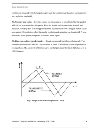
3.1 LIDAR
4
3.2 RADAR
6
3.2.1 PULSE DOPPLER RADAR
6
3.2.2 EFFECT OF DOPPLER SHIFT
7
3.2.3 RADAR ANTENNA SCHEMES
8
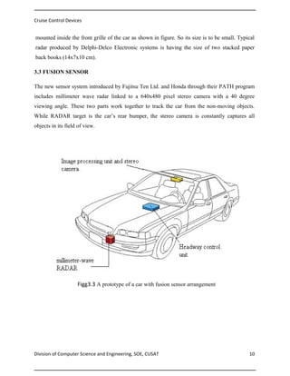
3.3 FUSION SENSOR
11
4. SPACE OF MANEUVERABILITY AND STOPPING DISTANCE:
13
5. CONTROLLER
14
5.1ARTIFICIAL COGNITION
14
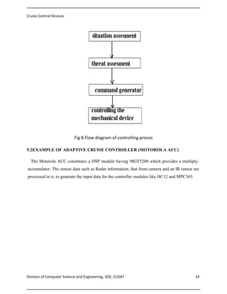
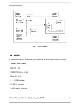
5.2. EXAMPLE OF ADAPTIVE CRUISE CONTROLLER
15
6. CO OPERATIVE ADAPTIVE CRUISE CONTROL [CACC]
18
6.1. MAIN POSTULATIONS ABOUT CACC
18
7. ADVANTAGES AND DISADVANTAGES
20
8. CONCLUSION
21
9. REFERENCE
22](https://image.slidesharecdn.com/cruisecontroldevices-131128014710-phpapp02/85/Cruise-control-devices-4-320.jpg)
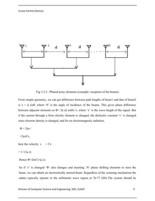
![Cruise Control Devices
So, if target moves, ‘R’ changes and hence ‘φ’ also changes.
Now, the rate of change of phase, or the ‘angular frequency’ is
W=dφ/dt =4 π (df/dt)/ λ
Let Vr be the linear velocity, called as ‘radial velocity’
WD = 4 πVr/ λ =2πfd.
Fd=2Vr / λ
But λ = ft, the transmitted velocity.
Fd= (2c Vr)/ ft
So by measuring the shift, Vr is found. The ‘plus’ sign indicates that the target and the
transmitter are closing in. i.e. if the target is near, the echoed signal will have larger frequency.
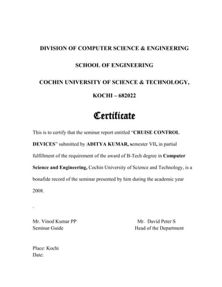
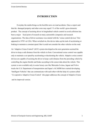
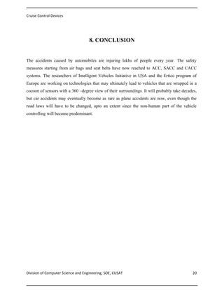
3.2.3 RADAR ANTENNA SCHEMES:
Radar systems employ a variety of sensing and processing methods to determine the position
and speed of vehicles ahead. Two such important schemes are:
1. mechanically steered antenna
2. electronically steered antenna
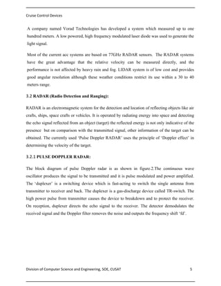
1. Mechanically steered antenna:
A parabolic reflector is used as mechanically steered antenna. The parabolic surface is
illuminated by the source of energy placed at the focus of the parabola. Rotating about
its
axis, a circular parabola is formed. A symmetrical beam can be thus obtained. The rays
originating from focus are reflected parallel to the axis of parabola. [Fig (3.2.3).]
Division of Computer Science and Engineering, SOE, CUSAT
7](https://image.slidesharecdn.com/cruisecontroldevices-131128014710-phpapp02/85/Cruise-control-devices-13-320.jpg)
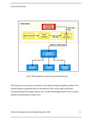
![Cruise Control Devices
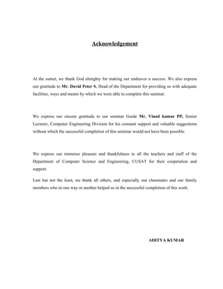
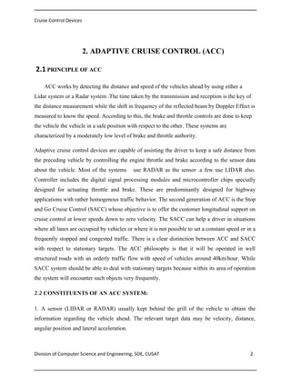
4. SPACE OF MANEUVERABILITY AND STOPPING DISTANCE
The space of maneuverability is the space required by the driver to maneuver a vehicle.
An average driver uses larger sideways acceleration while vehicle speed is low. If the curve
radius of a possible trajectory is ‘r’ for a given velocity ‘v’ and sideways acceleration ‘ay’ ,then
r=
/ ay [2].so to get the required ‘r’ ,when ‘v’ is low, ‘ay’ is also to be low correspondingly.
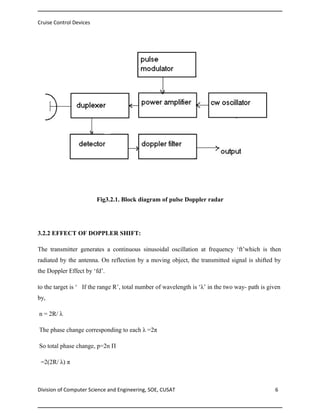
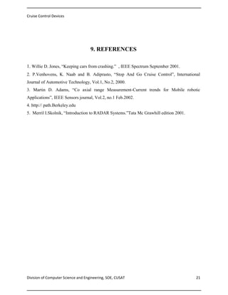
The stopping distance is given by, Ds = .5 u /ax + td u, where ‘u’ is the initial speed ‘td’ is the
time taken by the system to receive and process the sensor data and ‘ax’ is the acceleration of
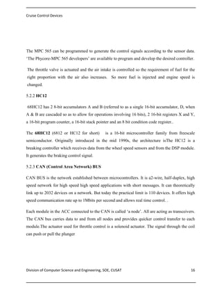
the vehicle .the figure shows the detection of edges of the preceding vehicles.
Fig 4.Detection of vehicle edges by the fusion sensor
Division of Computer Science and Engineering, SOE, CUSAT
12](https://image.slidesharecdn.com/cruisecontroldevices-131128014710-phpapp02/85/Cruise-control-devices-18-320.jpg)
![Cruise Control Devices
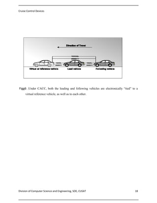
6. COOPERATIVE ADAPTIVE CRUISE CONTROL [CACC]
Though conventional ACC and SACC are still expensive novelties, the next generation
called Cooperative ACC is already being tested. While ACC can respond to the difference
between its own behavior and that of the preceding vehicle, the CACC system allows the
vehicles to communicate and to work together to avoid collision.
Partners of Advanced Transit Highways (PATH) –a program of California Department of
Transportation and University of California with
companies like Honda conducted an
experiment in which three test vehicles used a communication protocol in which the lead car
can broadcast information about its speed, acceleration ,breaking capacity to the rest of the
groups in every 20ms.
PATH is dedicated to develop systems that allow cars to set up platoons of vehicles in which the
cars communicate with each other by exchanging signals using protocols like Bluetooth.
6.1 MAIN POSTULATIONS ABOUT CACC:
1. In CACC mode, the preceding vehicles can communicate actively with the following s
Vehicle So that their speed can be coordinated with each other.
2.
Because communication is quicker, more reliable and responsive compared to autonomous
sensing as in ACC.
3.
Because braking rates, breaking capacity and other important information about the
vehicles can be exchanged, safer and closer vehicle traffic is possible.
Division of Computer Science and Engineering, SOE, CUSAT
17](https://image.slidesharecdn.com/cruisecontroldevices-131128014710-phpapp02/85/Cruise-control-devices-23-320.jpg)

This document summarizes a seminar report on cruise control devices presented by Aditya Kumar for a Bachelor of Technology degree. It discusses the principles and components of adaptive cruise control systems, which use sensors like LIDAR and radar to detect the distance and speed of preceding vehicles and control throttle and braking accordingly. Stop-and-go cruise control is described for congested traffic, while cooperative adaptive cruise control involves vehicles communicating with each other. The report provides details on LIDAR and pulse-Doppler radar operation and antenna schemes used in sensors. It concludes by addressing advantages and challenges of adaptive cruise control technologies.


![Cellonics-Seminar-Report[1]](https://cdn.slidesharecdn.com/ss_thumbnails/1bcc0cfd-2dd0-43ab-b83f-0ad9e75efb23-150829115235-lva1-app6892-thumbnail.jpg?width=640&height=640&fit=bounds)


