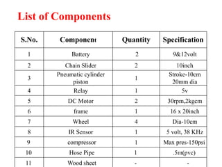
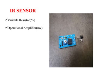
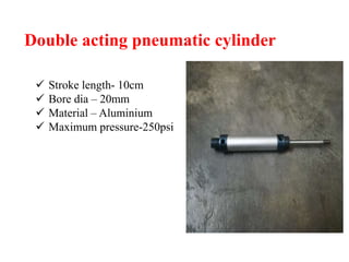
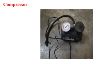
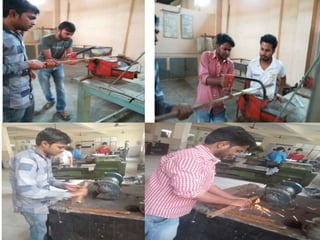
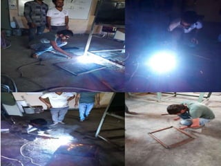
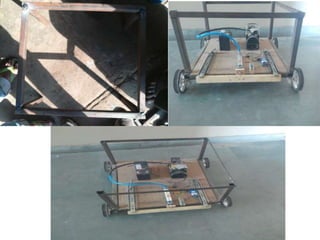
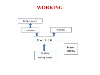
RAJ KUMAR GOEL INSTITUTE OF
TECHNOLOGY
PRESENTATION ON
AUTOMATIC PNEUMATIC BUMPER
AND BREAK ACTUATION BEFORE
COLLISION
Presented by:
ASHUTOSH Kr. SINGH
ANKAJ YADAV
MANTU KUMAR
PRASHANT SINGH
Under Guidence of:
Mr. Vivek Gupta
CONTENTS
Introduction
Objective of project
Important component
Working principal
Fabrication
Advantage
Disadvantage
Application
Conclusion
References
INTRODUCTION
• Accidents occur due to technical problem within the vehicle or due to
mistake of driver. Sometimes the drivers lose control over the vehicle
and sometimes accident occurs due to rash driving. When the drivers
come to know that vehicle is going to collide they become nervous and
they don’t apply the brakes. Majority of the accidents occur this way.
• The system designed will prevent such accidents. It keeps track of any
vehicles in front. It will continuously keep the track of the distance
between the two vehicles.
• When two come dangerously close the control unit receives the signal
reflecting back from the approaching body and gets activated . This
microprocessor controls the movement of actuators by the action of
which brake is applied.
OBJECTIVE OF PROJECT
 The objective of behind this project is to improve the prevention
technique of accidents and also reducing the hazard from accidents
like damage of vehicle, injury of human etc.
 To improve the pre-crash safety.
 To avoid the percentage of passenger injury by using external
vehicle safety
 It will also reduce the requirement air bags for inner safety which
costs very high while manufacturing and also during rewrapping
after the damage
List of Components
S.No. Component Quantity Specification
1 Battery 2 9&12volt
2 Chain Slider 2 10inch
3
Pneumatic cylinder
piston
1
Stroke-10cm
20mm dia
4 Relay 1 5v
5 DC Motor 2 30rpm,2kgcm
6 frame 1 16 x 20inch
7 Wheel 4 Dia-10cm
8 IR Sensor 1 5 volt, 38 KHz
9 compressor 1 Max pres-150psi
10 Hose Pipe 1 .5m(pvc)
11 Wood sheet - -
IR SENSOR
Variable Resistor(5v)
Operational Amplifier(mv)
Double acting pneumatic cylinder
 Stroke length- 10cm
 Bore dia – 20mm
 Material – Aluminium
 Maximum pressure-250psi
Compressor
WHEEL
Wheel Dia-10 cm
Robotics Wheel
Material- Rubber,Plastic
Transistor
Model: BC547
Transistor Type: NPN
One of the most common uses
for transistors in an electronic
circuit is as simple switches. In
short, a transistor conducts
current across the collector-
emitter path only when a
voltage is applied to the base.
When no base voltage is
present, the switch is off. When
base voltage is present, the
switch is on.
Relay Switch
5v DC
Electromagnetic Switch
Battery
Capacity- 12 V
Dry type
Li-ion Type
Chargeable
.
DC Motor
 Capacity- 12 volt
Weight- 180 gram
Torque- 2kgcm
Dia- 8mm
Rpm- 30
.
FABRICATION
Cutting:
Cutting of cast iron rod
Frame size – 20*16 inch
FINISHING:
In this we remove all rust particle
from the material and also remove
layer of paint before welding
WELDING
After the cutting all the
individual components. To
construct the frame, welding
of the individual components
is done.
ASSEMBLY
All the components are
assembled at their proper
position. A proper mounting
method is used to mount the
components.
WORKING
BUMPER MECHANISM
• The bumper is lined with absorptive material to absorb the energy of
the impact. Which in turn reduces the damage to the rest of the vehicle
and the driver and/or passengers in the vehicle.
• Once the control unit decides to actuate the bumper it sends a signal to
the flow control valve which gives the required quantity if the air to the
cylinder at which then actuates the bumper.
• In both the cases for the brake and the bumper double acting cylinders
are used so as it retract them with a reverse flow of the air to the
cylinder piston.
There are two main situations i.e. in one there is no any obstacle
and in other one , there is an obstacle . Hence both are depicted
below :-
(i)When any obstacle is NOT present , then in this case only one
LED is lightened and it indicates that the way is clear , and bumper
system is not activated which can be seen below as:-
(ii) When an obstacle is present in the way of vehicle then in this
case the Receiver receivesthe signal and sends it to the circuit
mounted on vehicle , which makes the secondLED also on
theDetection of the obstacle which can be seen below as
Comparison of Air Bags with Pneumatic Bumper System
• Air bags provide safety in case of severe accidents only, whereas, the
pneumatic bumper can provide safety even in case of minor
accidents.
• Air bags can provide only internal safety, but pneumatic bumper
system provides safety to external body of cars as well as internal
safety.
• Air bags can be deployed only once, whereas pneumatic bumper can
be used many times. Even if the bumper is damaged, it can be
replaced easily.
• The cost of air bags is higher than pneumatic bumper system.
ADVANTAGES
 It will increase the sureness of braking
Application also will increase the response time
of braking system.
 It will increase the pre-crash safety.
 it provide more safety to the passengers.
 This System plays an important role to save
human Life in road accidents.
DISADVANTAGE
 System has few limitations in densely traffic road.
 System has no provision to prevent and cure the accidents
from rear side of vehicle.
 Maintenance will be more due to the number of moving
parts.
 Stroke length is fixed.
 When accidental force is very high then the bumpers are
fails and these force transferred towards the passenger
APPLICATION
 This system may be applicable in all types of light vehicles
 like cars, Rickshaws, Tempos.
 This system also successfully installed in the heavy
 vehicles like buses, trucks, trailers, etc.
SCOPE
Our future work deals with incorporating this system with various
different features to provide enhanced protection by the intelligent
braking system in real time application. For that, some of the possible
changes are:
• 1) Infrared sensors can be replaced by ultrasonic sensors&other sensor.
• 2) Infrared sensors can sense eye blinking and give signal to solenoid
valve when driver sleeps.
• 3) Limit switch can be used to limit the minimum speed above which
the system gets triggered.
• 4) PIC can be implemented in system for further modifications like
gradual slowdown of vehicle.
• 5) Bumper design can further be enhanced to act as external air bags.
• 6) With some modifications, the project can be used with timer circuits
so as to apply brakes and extend the bumper after a delay of few
milliseconds so that the bumper does not extend unless the vehicle just
reaches the crashing distance.
CONCLUSION
The project is combination of the mechanical and Electronics,
which is fairly known as the Mechatronics. Our aim is to provide
safety before collision and if in case collision happens the system
should be able to save the passenger using the by absorbing
accidental force. Now a day’s vehicle accident is the major problem.
This breaking system used an automatic concept for the purpose of
preventing accidents. To overcome this problem developed system
is helpful for the reduction of road accidents. The IR sensor with
braking provide pre-crash safety and Bumper unit prevent further
damage to the vehicle in case of accident. Thus the system provides
safety to passenger as well as vehicle.
REFRENCES
1. Jordan, L.; Karthik, B.; Joswin, M.; Lobo, J.; Rijesh. (2016):
Fabrication of an automated collision avoidance system using
ultrasonic sensor, Journal of Mechanical Engineering and
Automation, 6(5A),. pp. 97-101.
2. Sammed, M.; Kesti, D.; Upadhye, J.; & Sumeet, A. (2016):
Design and Fabrication automatic pneumatic bumper and braking
system for four wheeler, FIESTA-16, pp.258- 360.
3. Katore, S.; Kadlag, S.; Mane, P.(2015): Automatic braking with
pneumatic bumper system, International Journal of Engineering,
3(2), pp. 97-101.
4. Sairam, G.; Suresh, B.; Hemanth,S.; Krishna,K. (2013):
Intelligent mechatronic braking system, International Journal of
Emerging Technology and Advanced Engineering, Vol.3, Issue 4,
pp.100-105.
5. Prof. Harshal Rahate1, “Experimental Work on Automatic
Pneumatic Bumper”, International Journal for Research in
Applied Science & Engineering Technology (IJRASET) ISSN: 2321-
9653; IC Value: 45.98; SJ Impact Factor:6.887 Volume 6 Issue I,
January 2018-
automatic braking system and brake actuation before collison

automatic braking system and brake actuation before collison

  • 1.
    RAJ KUMAR GOELINSTITUTE OF TECHNOLOGY PRESENTATION ON AUTOMATIC PNEUMATIC BUMPER AND BREAK ACTUATION BEFORE COLLISION Presented by: ASHUTOSH Kr. SINGH ANKAJ YADAV MANTU KUMAR PRASHANT SINGH Under Guidence of: Mr. Vivek Gupta
  • 2.
    CONTENTS Introduction Objective of project Importantcomponent Working principal Fabrication Advantage Disadvantage Application Conclusion References
  • 3.
    INTRODUCTION • Accidents occurdue to technical problem within the vehicle or due to mistake of driver. Sometimes the drivers lose control over the vehicle and sometimes accident occurs due to rash driving. When the drivers come to know that vehicle is going to collide they become nervous and they don’t apply the brakes. Majority of the accidents occur this way. • The system designed will prevent such accidents. It keeps track of any vehicles in front. It will continuously keep the track of the distance between the two vehicles. • When two come dangerously close the control unit receives the signal reflecting back from the approaching body and gets activated . This microprocessor controls the movement of actuators by the action of which brake is applied.
  • 4.
    OBJECTIVE OF PROJECT The objective of behind this project is to improve the prevention technique of accidents and also reducing the hazard from accidents like damage of vehicle, injury of human etc.  To improve the pre-crash safety.  To avoid the percentage of passenger injury by using external vehicle safety  It will also reduce the requirement air bags for inner safety which costs very high while manufacturing and also during rewrapping after the damage
  • 5.
    List of Components S.No.Component Quantity Specification 1 Battery 2 9&12volt 2 Chain Slider 2 10inch 3 Pneumatic cylinder piston 1 Stroke-10cm 20mm dia 4 Relay 1 5v 5 DC Motor 2 30rpm,2kgcm 6 frame 1 16 x 20inch 7 Wheel 4 Dia-10cm 8 IR Sensor 1 5 volt, 38 KHz 9 compressor 1 Max pres-150psi 10 Hose Pipe 1 .5m(pvc) 11 Wood sheet - -
  • 6.
  • 7.
    Double acting pneumaticcylinder  Stroke length- 10cm  Bore dia – 20mm  Material – Aluminium  Maximum pressure-250psi
  • 8.
  • 9.
    WHEEL Wheel Dia-10 cm RoboticsWheel Material- Rubber,Plastic
  • 10.
    Transistor Model: BC547 Transistor Type:NPN One of the most common uses for transistors in an electronic circuit is as simple switches. In short, a transistor conducts current across the collector- emitter path only when a voltage is applied to the base. When no base voltage is present, the switch is off. When base voltage is present, the switch is on.
  • 11.
  • 12.
    Battery Capacity- 12 V Drytype Li-ion Type Chargeable .
  • 13.
    DC Motor  Capacity-12 volt Weight- 180 gram Torque- 2kgcm Dia- 8mm Rpm- 30 .
  • 14.
    FABRICATION Cutting: Cutting of castiron rod Frame size – 20*16 inch
  • 15.
    FINISHING: In this weremove all rust particle from the material and also remove layer of paint before welding
  • 16.
    WELDING After the cuttingall the individual components. To construct the frame, welding of the individual components is done.
  • 17.
    ASSEMBLY All the componentsare assembled at their proper position. A proper mounting method is used to mount the components.
  • 21.
  • 22.
    BUMPER MECHANISM • Thebumper is lined with absorptive material to absorb the energy of the impact. Which in turn reduces the damage to the rest of the vehicle and the driver and/or passengers in the vehicle. • Once the control unit decides to actuate the bumper it sends a signal to the flow control valve which gives the required quantity if the air to the cylinder at which then actuates the bumper. • In both the cases for the brake and the bumper double acting cylinders are used so as it retract them with a reverse flow of the air to the cylinder piston.
  • 23.
    There are twomain situations i.e. in one there is no any obstacle and in other one , there is an obstacle . Hence both are depicted below :- (i)When any obstacle is NOT present , then in this case only one LED is lightened and it indicates that the way is clear , and bumper system is not activated which can be seen below as:-
  • 24.
    (ii) When anobstacle is present in the way of vehicle then in this case the Receiver receivesthe signal and sends it to the circuit mounted on vehicle , which makes the secondLED also on theDetection of the obstacle which can be seen below as
  • 25.
    Comparison of AirBags with Pneumatic Bumper System • Air bags provide safety in case of severe accidents only, whereas, the pneumatic bumper can provide safety even in case of minor accidents. • Air bags can provide only internal safety, but pneumatic bumper system provides safety to external body of cars as well as internal safety. • Air bags can be deployed only once, whereas pneumatic bumper can be used many times. Even if the bumper is damaged, it can be replaced easily. • The cost of air bags is higher than pneumatic bumper system.
  • 26.
    ADVANTAGES  It willincrease the sureness of braking Application also will increase the response time of braking system.  It will increase the pre-crash safety.  it provide more safety to the passengers.  This System plays an important role to save human Life in road accidents.
  • 27.
    DISADVANTAGE  System hasfew limitations in densely traffic road.  System has no provision to prevent and cure the accidents from rear side of vehicle.  Maintenance will be more due to the number of moving parts.  Stroke length is fixed.  When accidental force is very high then the bumpers are fails and these force transferred towards the passenger
  • 28.
    APPLICATION  This systemmay be applicable in all types of light vehicles  like cars, Rickshaws, Tempos.  This system also successfully installed in the heavy  vehicles like buses, trucks, trailers, etc.
  • 29.
    SCOPE Our future workdeals with incorporating this system with various different features to provide enhanced protection by the intelligent braking system in real time application. For that, some of the possible changes are: • 1) Infrared sensors can be replaced by ultrasonic sensors&other sensor. • 2) Infrared sensors can sense eye blinking and give signal to solenoid valve when driver sleeps. • 3) Limit switch can be used to limit the minimum speed above which the system gets triggered. • 4) PIC can be implemented in system for further modifications like gradual slowdown of vehicle. • 5) Bumper design can further be enhanced to act as external air bags. • 6) With some modifications, the project can be used with timer circuits so as to apply brakes and extend the bumper after a delay of few milliseconds so that the bumper does not extend unless the vehicle just reaches the crashing distance.
  • 30.
    CONCLUSION The project iscombination of the mechanical and Electronics, which is fairly known as the Mechatronics. Our aim is to provide safety before collision and if in case collision happens the system should be able to save the passenger using the by absorbing accidental force. Now a day’s vehicle accident is the major problem. This breaking system used an automatic concept for the purpose of preventing accidents. To overcome this problem developed system is helpful for the reduction of road accidents. The IR sensor with braking provide pre-crash safety and Bumper unit prevent further damage to the vehicle in case of accident. Thus the system provides safety to passenger as well as vehicle.
  • 31.
    REFRENCES 1. Jordan, L.;Karthik, B.; Joswin, M.; Lobo, J.; Rijesh. (2016): Fabrication of an automated collision avoidance system using ultrasonic sensor, Journal of Mechanical Engineering and Automation, 6(5A),. pp. 97-101. 2. Sammed, M.; Kesti, D.; Upadhye, J.; & Sumeet, A. (2016): Design and Fabrication automatic pneumatic bumper and braking system for four wheeler, FIESTA-16, pp.258- 360. 3. Katore, S.; Kadlag, S.; Mane, P.(2015): Automatic braking with pneumatic bumper system, International Journal of Engineering, 3(2), pp. 97-101. 4. Sairam, G.; Suresh, B.; Hemanth,S.; Krishna,K. (2013): Intelligent mechatronic braking system, International Journal of Emerging Technology and Advanced Engineering, Vol.3, Issue 4, pp.100-105. 5. Prof. Harshal Rahate1, “Experimental Work on Automatic Pneumatic Bumper”, International Journal for Research in Applied Science & Engineering Technology (IJRASET) ISSN: 2321- 9653; IC Value: 45.98; SJ Impact Factor:6.887 Volume 6 Issue I, January 2018-